Instruction Manual - M-System
Instruction Manual - M-System
Instruction Manual - M-System
- No tags were found...

Create successful ePaper yourself
Turn your PDF publications into a flip-book with our unique Google optimized e-Paper software.
INSTRUCTION MANUALCONTACT INPUT MODULE(32 points)MODELR1M-A1R1M-A1BEFORE USE ....Thank you for choosing M-<strong>System</strong>. Before use, please checkcontents of the package you received as outlined below.If you have any problems or questions with the product,please contact M-<strong>System</strong>’s Sales Office or representatives.This product is for use in general industrial environments,therefore may not be suitable for applications which requirehigher level of safety (e.g. safety or accident prevention systems)or of reliability (e.g. vehicle control or combustion controlsystems).For safety, installation and maintenance of this productmust be conducted by qualified personnel.■ PACKAGE INCLUDES:Remote I/O module....................................................... (1)■ MODEL NO.Confirm Model No. marking on the product to be exactlywhat you ordered.■ INSTRUCTION MANUALThis manual describes necessary points of caution whenyou use this product, including installation, connection andbasic maintenance procedures.For detailed information on Modbus supported functions,refer to Modbus Protocol Reference Guide (EM-5650).The R1M is programmable using the PC configurator software.For detailed information on the PC configuration,refer to the R1CON instruction manual. The R1CON PCConfigurator Software is downloadable at M-<strong>System</strong>’s website: http://www.m-system.co.jp.POINTS OF CAUTION■ CONFORMITY WITH EC DIRECTIVES• This equipment is suitable for use in a Pollution Degree2 environment and in Installation Category II, with themaximum operating voltage 300V.Basic insulation is maintained between the signal inputand RS-232C/RS-485. Prior to installation, check that theinsulation class of this unit satisfies the system requirements.• Altitude up to 2000 meters• The equipment must be mounted inside a panel.• Insert noise filters. Okaya Electric Industries Model SUP-E1H or equivalent for the power source connected to theunit, and TDK Model ZCAT3035-1330 or equivalent forthe RS-232C cable are recommended.• The equipment must be installed such that appropriateclearance and creepage distances are maintained to conformto CE requirements.• The actual installation environments such as panel configurations,connected devices, connected wires, may affectthe protection level of this unit when it is integratedin a panel system. The user may have to review the CErequirements in regard to the whole system and employadditional protective measures to ensure the CE conformity.■ POWER INPUT RATING & OPERATIONAL RANGE• Locate the power input rating marked on the product andconfirm its operational range as indicated below:100 – 240V AC rating: 85 – 264V, 47 – 66 Hz, approx. 10VA24V DC rating: 24V ±10%, approx. 7W■ GENERAL PRECAUTIONS• Before you remove the module, turn off the power supplyand input signal for safety.■ ENVIRONMENT• Indoor use• When heavy dust or metal particles are present in the air,install the module inside proper housing with sufficientventilation.• Do not install the module where it is subjected to continuousvibration. Do not apply physical impact to the module.• Environmental temperature must be within -5 to +60°C(23 to 140°F) with relative humidity within 30 to 90% RHin order to ensure adequate life span and operation.• Be sure that the ventilation slits are not covered with cables,etc.■ WIRING• Wrong connection may damage the module.• Do not connect cables to moving parts or pull them tightly.• Do not install cables (power supply, input and output)close to noise sources (relay drive cable, high frequencyline, etc.).• Do not bind these cables together with those in whichnoises are present. Do not install them in the same duct.■ AND ....• The module is designed to function as soon as power issupplied, however, a warm up for 10 minutes is requiredfor satisfying complete performance described in the datasheet.EM-5661 Rev.4P. / 4
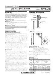
R1M-A1COMPONENT IDENTIFICATION■ REAR VIEWRS-485ConnectorPower TerminalsRS-232C9-pin ConnectorAddress SettingRotary SWSpecifications MarkingRUN IndicatorLEDConfiguratorJackINSTALLATION■ DIN RAIL MOUNTINGSet the body so that its DIN railadaptor is at the bottom. Pulldown the DIN rail adaptor.Position the upper hook at therear side on the DIN rail andpush in the lower. Push back theDIN rail adaptor.DIN Rail35mm wide■ WALL MOUNTINGSet the body so that its DIN railadaptor is at the bottom. PullDIN Rail Adaptordown the DIN rail adaptor.Refer to “EXTERNAL DIMENSIONS.”TERMINAL CONNECTIONSConnect the module referring to the connection diagram.■ FCN TYPE CONNECTOR■ M3 SCREW TERMINALSCN1CN2ch.1ch.2ch.3ch.4ch.5ch.6ch.7ch.8ch.9ch.10ch.11ch.12ch.13ch.14ch.15ch.16COM (–)ch.17ch.18ch.19ch.20ch.21ch.22ch.23ch.24ch.25ch.26ch.27ch.28ch.29ch.30ch.31Count Reset Input ch.32COM (–)A1A2A3A4A5A6A7A8A9A10A11A12A13A14A15A16B1:B16A1A2A3A4A5A6A7A8A9A10A11A12A13A14A15A16B1:B16Input Circuitch.1ch.2ch.3ch.4ch.5ch.6ch.7ch.8COM (–)ch.9ch.10ch.11ch.12ch.13ch.14ch.15ch.16COM (–)ch.17ch.18ch.19ch.20ch.21ch.22ch.23ch.24COM (–)ch.25ch.26ch.27ch.28ch.29ch.30ch.31Count Reset Input ch.32COM (–)123456789101112131415161718192021222324252627282930313233343536Input CircuitOutputCircuitTerm.Resist.PowerCircuitT1T2T3T4T5T6T7RS-232C* When the device is located at the end of a transmission line via twisted-pair cable,(when there is no cross-wiring), close across the terminal T2 – T3 with the attachedjumper pin (or with a leadwire).When the device is not at the end, remove the jumper pin.D-SUB CONNECTOR+–U (+)V (–)FGShielded Twisted-pair CableTo OtherI/O ModulesJumper*POWEREM-5661 Rev.4P. / 4
R1M-A1■ RS-232C INTERFACE1 56 9ABBR. PIN NO. EXPLANATION OF FUNCTIONBA (SD) 2 Transmitted DataBB (RD) 3 Received DataAB (SG) 5 Signal CommonCB (CS) 7 Clear to SendCA (RS) 8 Request to Send1 Not Used.4 DO NOT connect. Connecting may6 cause malfunctions.9MODBUS WIRING CONNECTIONRS-232CCONNECTORR1MT1T2T3T4RS-485R1MRS-485R1MT1T2T1T2* 1 T3T4T3T4* 1FG *2*1. Internal terminating resistor is used when the device is at the end of a transmission line.*2. Install shielded cables to all sections and ground them at single point.CHECKING1) Terminal wiring: Check that all cables are correctly connectedaccording to the connection diagram.2) Power input: Check supply voltage.ADJUSTMENT PROCEDUREThis unit is calibrated at the factory to meet the orderedspecifications, therefore you usually do not need any calibration.EM-5661 Rev.4P. / 4
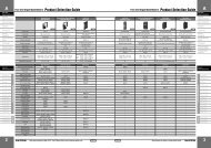
R1M-A1EXTERNAL DIMENSIONS unit: mm (inch)■ SCREW TERMINALS175 (6.89)10 (.39)165 (6.50)T1 T2 T3 T4T5 T6 T73–5 (.20) dia.MTG HOLES15.5 (.61)46 (1.81)105 (4.13)104 (4.09)DIN RAIL35 mm wide1 2 3 4 5 6 7 8 9 10 11 12 13 14 15 16 17 1819 20 21 22 23 24 25 26 27 28 29 30 31 32 33 34 35 3514 (.55)163 (6.42)FOR WALL MOUNT.3 (.12)40 (1.57)[6 (.24)]6.2 (.24)36–M3 I/O TERMINALS■ FCN TYPE CONNECTOR175 (6.89)40 (1.57)10 (.39)165 (6.50)T1 T2 T3 T4T5 T6 T73–5 (.20) dia.MTG HOLES15.5 (.61)46 (1.81)Connector PinAssignmentA1 B1105 (4.13)104 (4.09)DIN RAIL35 mm wideCN1CN2See Caution belowA16B1614 (.55)FCN TYPE I/O CONNECTOR163 (6.42)FOR WALL MOUNT.40 (1.57)3 (.12)[6 (.24)]Caution: DO NOT APPLY EXCESSIVE FORCE ontothe connector. The connector may be destroyed.M-SYSTEM WARRANTYM-<strong>System</strong> warrants such new M-<strong>System</strong> product which it manufactures to be free from defects in materials and workmanship during the 36-month period following the date that suchproduct was originally purchased if such product has been used under normal operating conditions and properly maintained, M-<strong>System</strong>’s sole liability, and purchaser’s exclusiveremedies, under this warranty are, at M-<strong>System</strong>’s option, the repair, replacement or refund of the purchase price of any M-<strong>System</strong> product which is defective under the terms of thiswarranty. To submit a claim under this warranty, the purchaser must return, at its expense, the defective M-<strong>System</strong> product to the below address together with a copy of its originalsales invoice.THIS IS THE ONLY WARRANTY APPLICABLE TO M-SYSTEM PRODUCT AND IS IN LIEU OF ALL OTHER WARRANTIES, EXPRESS OR IMPLIED, INCLUDING ANY IMPLIEDWARRANTIES OF MERCHANTABILITY OR FITNESS FOR A PARTICULAR PURPOSE. M-SYSTEM SHALL HAVE NO LIABILITY FOR CONSEQUENTIAL, INCIDENTAL ORSPECIAL DAMAGES OF ANY KIND WHATSOEVER.M-<strong>System</strong> Co., Ltd., 5-2-55, Minamitsumori, Nishinari-ku, Osaka 557-0063 JAPAN, Phone: (06) 6659-8201, Fax: (06) 6659-8510, E-mail: info@m-system.co.jpEM-5661 Rev.4P. / 4