MODEL: 48NDV - M-System
MODEL: 48NDV - M-System
MODEL: 48NDV - M-System

Create successful ePaper yourself
Turn your PDF publications into a flip-book with our unique Google optimized e-Paper software.
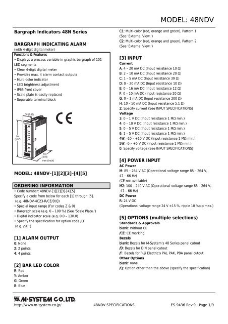
<strong>MODEL</strong>: <strong>48NDV</strong>Bargraph Indicators 48N SeriesBARGRAPH INDICATING ALARM(with 4-digit digital meter)Functions & Features• Displays a process variable in graphic bargraph of 101LED segments• Clear 4-digit digital meter• Provides max. 4 alarm contact outputs• Multi-color indicator• LED brightness adjustment• IP65 front cover• Scale plate is easily replaced• Separable terminal block144(5.67)50403020100102030405036 (1.42)100 SET9080706050403020100HSPZLMm 3/h % mA103(4.06)mm (inch)<strong>MODEL</strong>: <strong>48NDV</strong>–[1][2][3]–[4][5]ORDERING INFORMATION• Code number: <strong>48NDV</strong>-[1][2][3]-[4][5]Specify a code from below for each [1] through [5].(e.g. <strong>48NDV</strong>-4C23-R/CE/D/Q)• Special input range (For codes Z & 0)• Bargraph scale (e.g. 0 – 100 %) (See ‘Scale Plate.’)• Digital indicator scale (e.g. 0.0 – 130.0)• Specify the specification for option code /Q(e.g. /SET)[1] ALARM OUTPUT0: None2: 2 points4: 4 points[2] BAR LED COLORR: RedY: AmberG: GreenB: BlueC1: Multi-color (red, orange and green), Pattern 1(See ‘External View.’)C2: Multi-color (red, orange and green), Pattern 2(See ‘External View.’)[3] INPUTCurrentA: 4 – 20 mA DC (Input resistance 10 Ω)B: 2 – 10 mA DC (Input resistance 20 Ω)C: 1 – 5 mA DC (Input resistance 39 Ω)D: 0 – 20 mA DC (Input resistance 10 Ω)E: 0 – 16 mA DC (Input resistance 12 Ω)F: 0 – 10 mA DC (Input resistance 20 Ω)G: 0 – 1 mA DC (Input resistance 200 Ω)H: 10 – 50 mA DC (Input resistance 5.1 Ω)Z: Specify current (See INPUT SPECIFICATIONS)Voltage3: 0 – 1 V DC (Input resistance 1 MΩ min.)4: 0 – 10 V DC (Input resistance 1 MΩ min.)5: 0 – 5 V DC (Input resistance 1 MΩ min.)6: 1 – 5 V DC (Input resistance 1 MΩ min.)4W: -10 – +10 V DC (Input resistance 1 MΩ min.)5W: -5 – +5 V DC (Input resistance 1 MΩ min.)0: Specify voltage (See INPUT SPECIFICATIONS)[4] POWER INPUTAC PowerM: 85 – 264 V AC (Operational voltage range 85 – 264 V,47 – 66 Hz)(CE not available)M2: 100 – 240 V AC (Operational voltage range 85 – 264 V,47 – 66 Hz)DC PowerR: 24 V DC(Operational voltage range 24 V ±15 %, ripple 10 %p-p max.)[5] OPTIONS (multiple selections)Standards & Approvalsblank: Without CE/CE: CE markingBezelsblank: Bezels for M-<strong>System</strong>’s 48 Series panel cutout/D: Bezels for DIN panel cutout/F: Bezels for Fuji Electric's PAJ, PAK, PBA panel cutoutOther Optionsblank: none/Q: Option other than the above (specify the specification)http://www.m-system.co.jp/ <strong>48NDV</strong> SPECIFICATIONS ES-9436 Rev.9 Page 1/9
<strong>MODEL</strong>: <strong>48NDV</strong>SPECIFICATIONS OF OPTION: QEX-FACTORY SETTING/SET: Preset according to the Ordering Information Sheet(No. ESU-9436)BEZEL OPTIONBezels are used to adapt the 48N Series to an existing panelcutout. In order to replace M-<strong>System</strong>’s 48 Series products,use the one attached to the 48N Series as standard. Whenthe existing panel is cut according to DIN standard, specify‘/D’ suffix code.For a new installation, no bezel is required. Please refer to‘Mounting Requirement’ and mount the 48N directly.Ingress protection is invalid when the 48N is mounted with abezel, or when multiple modules are stacked side by side.SPARE PARTS• Scale plateGENERAL SPECIFICATIONSConstruction: Panel flush mountingDegree of protection: IP65; applicable to the front panel forsingle unit mounted according to the specified panel cutoutConnection: M3 screw terminals (torque 0.6 N·m)Screw terminal: Nickel-plated steelHousing material: Flame-resistant resin (black)Isolation: Input to output to powerZero adjustment: -10 to +10 % (front)Span adjustment: 90 to 110 % (front)Scale plate: Flame resistant resin (white scale & characterson black base)H & L alarm output delay: 0 sec. (factory setting;fieldselectable between 0 and 15 sec. by 1 sec. increments)Setpoint adjustment2 points:H [L setpoint ] to 100 %L 0 to [H setpoint]or No alarm trip4 points:HH [H setpoint] to 100 %H [L setpoint] to [HH setpoint]L [LL setpoint] to [H setpoint]LL 0 to [L setpoint]or No alarm tripAlarm deadband (hysteresis): 1 %Setting: (Front button)• Zero and span adjustments• Alarm setpoint• Others(Refer to the instruction manual for details)Read rate: 10/sMoving average sample number: 4 (factory setting; fieldselectable among 1, 2, 4, 8 or 16)■ BARGRAPHLED: 101-segment LED, 100 mm (3.96”) long, 3.00 mm(.12”) wideDisplay range: 0 to 100 (scaling function not available)Scale: Two different scales available for single bargraphCharacters: Max. 4 characters including decimal point andnegative signDivisions: Min. 22, max. 100Engineering unit: Max. 6 characters■ DIGITAL DISPLAYSLED: 7-segment red LED, 8 mm (.31”) highNumber of digits: 4 digitsScaled range: -1999 to 0 to 9999(Min. 3 significant digits)Minimum scale value: 100 (3 digits, the decimal pointposition disregarded)Overrange: The indicator blinks when the input is out of therange from -15 to +115 %.Decimal point position: 10 –1 , 10 –2 , 10 –3 or noneZero indication: Higher-digit zeros are suppressedEngineering unit: Max. 6 characters on scale plateLED brightness adjustment: 7 levelsINPUT SPECIFICATIONS■ DC Current: 0 – 50 mA DC; input resistor incorporatedMinimum span: 1 mAWhen specifying a resistance value, choose from below.5.1 Ω, 10 Ω, 12 Ω, 20 Ω, 39 Ω, 200 Ω■ DC Voltage: -10 – +10 V DCInput resistance: ≥ 1 MΩMinimum span: 0.1 VOffset: Max. 1.5 times spanOUTPUT SPECIFICATIONS■ Alarm Output: Relay contactRated load: 250 V AC @1 A (cos ø = 1)30 V DC @5 A (resistive load)Maximum switching voltage: 250 V AC, 220 V DCMaximum switching power: 380 VA, 150 WMinimum load: 5 V DC @100 mAMechanical life: ≥ 5 × 10 8 cycles (rate 180 cycles/min.)INSTALLATIONPower Consumption•AC: Approx. 6 VA•DC: Approx. 2.5 WOperating temperature: -5 to +55°C (23 to 131°F)http://www.m-system.co.jp/ <strong>48NDV</strong> SPECIFICATIONS ES-9436 Rev.9 Page 2/9
<strong>MODEL</strong>: <strong>48NDV</strong>Operating humidity: 30 to 90 %RH (non-condensing)Mounting: Panel flush mountingWeight: 300 g (0.66 lb)PERFORMANCE in percentage of spanAccuracyBargraph: ±1 % ±1 digitDigital indicator: ±0.5 % ±1 digitTemp. coefficient: ±0.015 % of FS/°C (±0.008 % of FS/°F)Response time: ≤ 0.5 sec.(moving average sample number set to 4)Insulation resistance: ≥ 100 MΩ with 500 V DCDielectric strength: 2000 V AC @1 minute (input to outputto power to ground)STANDARDS & APPROVALSCE conformity:EMC Directive (2004/108/EC)EMI EN 61000-6-4: 2007EMS EN 61000-6-2: 2005Low Voltage Directive (2006/95/EC)EN 61010-1: 2001Installation Category IIPollution Degree 2Input to output to power – Reinforced insulation (300 V)http://www.m-system.co.jp/ <strong>48NDV</strong> SPECIFICATIONS ES-9436 Rev.9 Page 3/9
<strong>MODEL</strong>: <strong>48NDV</strong>SCALE PLATE■ WHAT MUST BE SPECIFIED WHEN ORDERINGPlease specify the bargraph scale range and engineering unit. The overvall scale plate design including the number ofdivisions, division line length, character font is determined by M-<strong>System</strong>.[Example] : Bargraph range 0 to 300 cmBargraph scale range: 0 – 300Engineering unit for the bargraph: cm■ TYPES OF DIVISIONSFive (5) types of divisions are used depending upon the scale span, which determined by the following equation:nScale Span = (Max. range value – Min. range value) x 10where n = integer (used to limit the calculated scale span to the minimum of 1.1, below 11.0.)The number of divisions is automatically determined by the scale span.• Type 1: 1.1 Scale Span < 1.3Number of divisions: 22 to 25.9Scale: Starts at 0, increments by 0.02 / 0.2 / 2 / 20 /200. Min. and max. values indicated. 4 digitsincluding negative sign and decimal point.Division lines: Long, Short, Medium, Short, Long(4 divisions repeated)• Type 3: 2.0 Scale Span < 2.6Number of divisions: 40 to 51.9Scale: Starts at 0, increments by 0.05 / 0.5 / 5 / 50 /500. Min. and max. values indicated. 4 digitsincluding negative sign and decimal point.Division lines: Long, Short, Medium, Short, Medium,Short, Medium, Short, Medium, Short, Long(10 divisions repeated)MinimumDivisionsMaximumDivisionsBipolarScaleMinimumDivisionsMaximumDivisionsBipolarScale1110864201.291.21.00.80.60.40.26004002000-200-4000 -60020151052.5921.510.50 0120100500-50-100-120• Type 2: 1.3 Scale Span < 2.0Number of divisions: 26 to 39.9Scale: Starts at 0, increments by 0.03 / 0.3 / 3 / 30 /300. Min. and max. values indicated. 4 digitsincluding negative sign and decimal point.Division lines: Long, Short, Medium, Short, Medium,Short, Long (6 divisions repeated)• Type 4: 2.6 Scale Span < 5.5Number of divisions: 26 to 54.9Scale: Starts at 0, increments by 0.05 / 0.5 / 5 / 50 /500. Min. and max. values indicated. 4 digitsincluding negative sign and decimal point.Division lines: Long, Medium, Medium, Medium,Medium, Long (5 divisions repeated)MinimumDivisionsMaximumDivisionsBipolarScaleMinimumDivisionsMaximumDivisionsBipolarScale13012090603001.991.8 0.61.51.20.90.60.300.80.30-0.3-0.6-0.8260250200150100505.4954.543.532.521.510.50 0250200150100500-50-100-150-200-250http://www.m-system.co.jp/ <strong>48NDV</strong> SPECIFICATIONS ES-9436 Rev.9 Page 4/9
<strong>MODEL</strong>: <strong>48NDV</strong>• Type 5: 5.5 Scale Span < 11.0Number of divisions: 27.5 to 54.9Scale: Starts at 0, increments by 0.01 / 0.1 / 1 / 10 /100 / 1000. Min. and max. values indicated.4 digits including negative sign and decimalpoint.Division lines: Long, Medium, Medium, Medium,Medium, Long (5 divisions repeated)[Example] : Bargraph range 0 to 300 cm (Type 4)Digital indicator range 0.00 to 6.75 m 3(Type 4)Left scale range: 0 – 300Left scale unit (bargraph): cmRight scale: NoneDigital indicator unit: m 3MinimumDivisions5505004003002001000MaximumDivisions10.9109876543210BipolarScale0.50.40.30.20.10-0.1-0.2-0.3-0.4-0.5300250200150100500cmSETHHHSPZLLLMm 3http://www.m-system.co.jp/ <strong>48NDV</strong> SPECIFICATIONS ES-9436 Rev.9 Page 5/9
<strong>MODEL</strong>: <strong>48NDV</strong>EXTERNAL VIEW■ ALARM SUFFIX CODE 0: None• Bar Color PatternsPattern 1 (model suffix code C1)Setpoint 25040302010100 SET9080270 S60 PSET (ENTER) ButtonColor Setpoint 2 Adj. (red)Span Adj. (amber)Decimal Point Position Adj. (amber)Input < L L < Input < H H < InputHredLgreen greenorange orange orangeSetpoint 10-105040Z1Zero Adj. (amber)Color Setpoint 1 Adj. (green)Pattern 2 (model suffix code C2)PV Indicator-20-30-40302010MUP ButtonMode SelectorHLorangegreengreenredredred-500DOWN Buttonm 3/h % mASetpoint 1 or 2 provided only for the multi-color bar type.■ ALARM SUFFIX CODE 2: 2 pointsH Setpoint5040100 SET90SET (ENTER) Button3080HH Setpoint Adj. & Trip Indicator (red)2070SSpan Adj. (amber)1060PDecimal Point Position Adj. (amber)L Setpoint0-105040ZLZero Adj. (amber)L Setpoint Adj. & Trip Indicator (green)-2030UP ButtonPV Indicator-30-402010MMode Selector-500DOWN Buttonm 3/h % mA■ ALARM SUFFIX CODE 4: 4 pointsHH Setpoint504030100 SET90HH80HSET (ENTER) ButtonHH Setpoint Adj. & Trip Indicator (red)H Setpoint Adj. & Trip Indicator (red)H SetpointL SetpointLL Setpoint20100-1070605040SPZLLLSpan Adj. (amber)Decimal Point Position Adj. (amber)Zero Adj. (amber)L Setpoint Adj. & Trip Indicator (green)LL Setpoint Adj. & Trip Indicator (green)-2030UP ButtonPV Indicator-30-402010MMode Selector-500DOWN Buttonm 3/h % mAhttp://www.m-system.co.jp/ <strong>48NDV</strong> SPECIFICATIONS ES-9436 Rev.9 Page 6/9
DIMENSIONS unit: mm (inch)4 * 1(.16)2–M3 SCREWS16–M3 SCREWTERMINALS<strong>MODEL</strong>: <strong>48NDV</strong>144 (5.67)100 (3.94)12345678910111213141516137.5 (5.41)36 (1.42) 10 (.39) 75 (2.95)1831 (1.22)103 (4.06) (.71)■ STANDARD BEZEL* 2 10.4■ OPTION /D BEZEL* 3■ OPTION /F BEZEL* 4Rounded corners for the option /D4.9(.19)136.5 (5.37)144 (5.67)3.9(.15)136.5 (5.37)144 (5.67)8.5(.33)136.5 (5.37)144 (5.67)11.4(.45)7.5(.30)(.41)7.5(.30)10.4(.41)7.5(.30)*1. Space required when replacing the scale plate.*2. Used for the existing panel cutout of M-<strong>System</strong> 48 Series (38 × 139.5 mm).*3. Used for the existing DIN panel cutout (33 × 138 mm)*4. Used for the existing panel cutout of Fuji Electric PAJ, PAK, PBA (44 × 138 mm), etc.http://www.m-system.co.jp/ <strong>48NDV</strong> SPECIFICATIONS ES-9436 Rev.9 Page 7/9
<strong>MODEL</strong>: <strong>48NDV</strong>PANEL CUTOUT unit: mm■ SINGLE MOUNTING (ingress protection)■ CLUSTERED MOUNTING (no ingress protection)138 +1–031.5+1–0Panel thickness: 1.6 – 8.0 mm138 +1–0LPanel thickness: 1.6 – 8.0 mmL = {31.5 + 36 × (N – 1)}(N : number of units)+1–0Note 1. Observe at the minimum of 3 cmabove and below the units forheat dissipation.Note 2. No bezel is needed whenthe panel is cut according tothe left drawings.SCHEMATIC CIRCUITRY & CONNECTION DIAGRAM■ ALARM SUFFIX CODE 0: None■ ALARM SUFFIX CODE 2: 2 pointsINPUT+–12345*Low DriftAmplifierDisplay /SettingDigitalComputation7891213DigitalComputationRyRy7 Hc8 Ha9 Hb12 La13 LbH OUTPUTL OUTPUT61414Lc10111516U (+)POWERV (–)1516U (+)V (–)POWER*Input shunt resistor incorporated for current input.■ ALARM SUFFIX CODE 4: 4 pointsINPUT+–12345*Low DriftAmplifierDisplay /SettingDigitalComputationRyRyRy7 Hc, HHc8 HHa HH OUTPUT9 HHbH OUTPUT10 Ha11 La6Ry1213LLaLLbLL OUTPUTL OUTPUT14Lc, LLc1516U(+)V(–)POWER■ Relay Protection• AC PoweredLOAD*Input shunt resistor incorporated for current input.InductiveLoad (Coil)Varistor orCR Circuit• DC PoweredLOADInductiveLoad (Coil)Diode, Varistoror CR Circuithttp://www.m-system.co.jp/ <strong>48NDV</strong> SPECIFICATIONS ES-9436 Rev.9 Page 8/9
<strong>MODEL</strong>: <strong>48NDV</strong>Specifications are subject to change without notice.http://www.m-system.co.jp/ <strong>48NDV</strong> SPECIFICATIONS ES-9436 Rev.9 Page 9/9