368KB - M-System
368KB - M-System
368KB - M-System

Create successful ePaper yourself
Turn your PDF publications into a flip-book with our unique Google optimized e-Paper software.
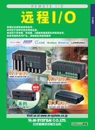
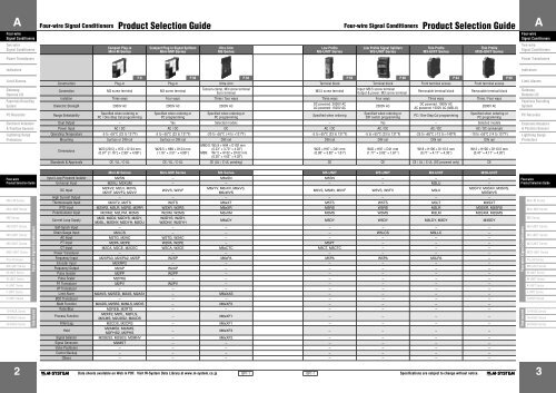
AFour-wire Signal Conditioners Product Selection GuideFour-wire Signal Conditioners Product Selection GuideAFour-wireSignal ConditionersFour-wireSignal ConditionersTwo-wireSignal ConditionersCompact Plug-inMini-M SeriesCompact Plug-in Signal SplittersMini-MW SeriesUltra-SlimM6 SeriesLow ProfileM5-UNIT SeriesLow Profile Signal SplittersW5-UNIT SeriesThin ProfileM3-UNIT SeriesThin ProfileM3S-UNIT SeriesTwo-wireSignal ConditionersPower TransducersPower TransducersIndicatorsIndicatorsLimit AlarmsGateway,Remote I/OPaperless Recording<strong>System</strong>PC RecorderElectronic Actuators& Position SensorsLightning SurgeProtectorsP.8 P.30 P.38 P.56 P.60 P.64 P.68Construction Plug-in Plug-in Ultra-slim Terminal block Terminal block Front terminal access Front terminal accessConnection M3 screw terminal M3 screw terminalTension-clamp, M3 screw terminalEuro terminalM3.5 screw terminalInput: M3.5 screw terminalOutput & power: M3 screw terminalRemovable terminal blockRemovable terminal blockIsolation Three ways Four ways Three / four ways Three ways Four ways Three ways Three / Four waysDielectric Strength 2000V AC 2000V AC 2000V ACRange SelectabilitySpecified when ordering orPC / One-Step Cal programmingSpecified when ordering orPC programmingSpecified when ordering orPC programmingDC powered: 2000V ACAC powered: 1500V ACSpecified when ordering2000V ACSpecified when ordering orDIP switch programmingDC powered: 1000V ACAC powered: 1500V AC (M3LU)PC / One-Step Cal programming2000V ACSpecified when ordering orPC programmingDual Output – Yes Selected models – Yes – Selected modelsPower Input AC / DC AC / DC DC AC / DC AC / DC AC / DC AC / DC (universal)Operating Temperature -5 to +55°C (23 to 131°F) -5 to +55°C (23 to 131°F) -20 to +55°C (-4 to +131°F) -5 to +55°C (23 to 131°F) -5 to +55°C (23 to 131°F) -25 to +65°C (-13 to +149°F) -10 to +55°C (14 to 131°F)Mounting Surface or DIN rail Surface or DIN rail DIN rail mm (inch)DIN rail DIN rail DIN rail DIN railM6D/S: W5.9 × H94 × D102 mmDimensionsW23 [29.5] × H76 × D124 mm W29.5 × H89 × D124 mm(0.23” × 3.70” × 4.02”)W25 × H97 × D41 mmW45 × H97 × D41 mmW18 × H106 × D110.5 mm W12 × H106 × D110.5 mm(0.91” [1.16”] × 2.99” × 4.88”) (1.16” × 3.51” × 4.88”) M6N: W7.5 × H102 × D102 mm(0.98” × 3.82” × 1.61”)(1.77” × 3.82” × 1.61”)(0.71” × 4.17” × 4.35”)(0.47” × 4.17” × 4.35”)(0.30” × 4.02” × 4.02”)Standards & Approvals CE / UL / C-UL CE / UL / C-UL CE (UL / C-UL pending) CE CE CE / UL / C-UL (DC powered only) CELimit AlarmsGateway,Remote I/OPaperless Recording<strong>System</strong>PC RecorderElectronic Actuators& Position SensorsLightning SurgeProtectorsFour-wireProduct Selection GuideMini-M SeriesMini-MW SeriesM6 SeriesM5-UNIT SeriesW5-UNIT SeriesM3-UNIT SeriesM3S-UNIT SeriesPico-M SeriesMX-UNIT SeriesM-UNIT SeriesW-UNIT SeriesK-UNIT SeriesF-UNIT SeriesH-UNIT Series10-RACK Series18-RACK Series38-RACK Series2Four-wire Signal ConditionersRack-mountedMini-M Series Mini-MW Series M6 Series M5-UNIT W5-UNIT M3-UNIT M3S-UNITInput Loop Powered Isolator M2SN – M6xSN M5SN – – –Universal Input M2XU, M2XUM – – – – M3LU –DC InputM2XV2, M2LV, M2VS,M2VF, M2VF2, M2VVW2VS, W2VFData sheets available on Web in PDF. Visit M-<strong>System</strong> Data Library at www.m-system.co.jpM6xYV, M6xXV, M6xVS,M6xWVSISP1-1ISP1-1M5VS, M5MV, M5VF W5VS, W5FV M3LVSpecifications are subject to change without notice.M3SYV, M3SXV, M3SVS,M3SWVSHigh Current Output – – – – – – –Thermocouple Input M2XT2, M2TS W2TS M6xXT M5TS W5TS M3LT M3SXTRTD Input M2XR2, M2LR, M2RS, M2RR W2XR, W2RS M6xXR M5RS W5RS M3LR M3SXR, M3SRSPotentiometer Input M2XM2, M2LPM, M2MS W2XM, W2MS M6xXM M5MS W5MS M3LM M3SXM, M3SMSCurrent Loop SupplyM2D, M2D2, M2DYS, M2DY,M2DL, M2DNY, M2DYH, M2DUW2DYS, W2DY,W2DNY, W2DYHM6xDY M5DY W5DY M3LDY, M3DY M3SDYSelf-Synch Input – – – – – – –Strain Gauge Input M2LCS – – – W5LCS M3LLC –AC Input M2TG, M2AC W2TG, W2AC – – – – –PT Input M2PA, M2PE W2PA, W2PE – M5PT – – –CT Input M2CA, M2CE, M2CEC W2CA, W2CE M6xCTC M5CT, M5CTC – – –Power Transducer – – – – – – –Frequency Input M2XPA3, M2XPA2, M2SP W2SP M6xPA M5PA W5PA M3LPA –Encoder Input M2XRP2 – – – – – –Frequency Output M2AP W2AP – – – – –Pulse Isolator M2PP W2PP – – – – –Pulse Scaler M2PRU – – – – – –P/I Transducer M2PV W2PV – – – – –I/P Transducer – – – – – – –Limit Alarm M2AVS, M2SED, M2AS, M2AS1 – M6xXAS – – – –BCD Transducer – – – – – – –Math Function M2ADS, M2SBS, M2MLS, M2DIS – M6xXF2 – – – –Ratio/Bias M2REB, M2RTS – – – – – –Process FunctionM2XF2, M2FL, M2FLS,M2LMS, M2UDS2, M2UDS– M6xXF1 – – – –Filter/Lag M2CDS, M2CRS – M6xXF1 – – – –HoldM2AMS2, M2AMS,M2PHS2, M2PHS– M6xXF3 – – – –Signal Selector M2SES2, M2SES, M2MNV – M6xXF2 – – – –Signal Generator M2MST – – – – – –Valve Positioner – – – – – – –Control Backup – – – – – – –Others – – – – – – –Four-wireProduct Selection GuideFour-wire Signal ConditionersRack-mountedMini-M SeriesMini-MW SeriesM6 SeriesM5-UNIT SeriesW5-UNIT SeriesM3-UNIT SeriesM3S-UNIT SeriesPico-M SeriesMX-UNIT SeriesM-UNIT SeriesW-UNIT SeriesK-UNIT SeriesF-UNIT SeriesH-UNIT Series10-RACK Series18-RACK Series38-RACK Series3
AFour-wire Signal Conditioners Product Selection GuideFour-wire Signal Conditioners Product Selection GuideAFour-wireSignal ConditionersFour-wireSignal ConditionersTwo-wireSignal ConditionersPower TransducersDual Output Super-mini SignalConditionersPico-M SeriesPlug-in Front ConfigurableMX-UNIT SeriesPlug-inM-UNIT SeriesPlug-in Signal SplittersW-UNIT SeriesPlug-inK-UNIT SeriesSpace-saving Plug-inF-UNIT SeriesSpace-saving Plug-inH-UNIT SeriesTwo-wireSignal ConditionersPower TransducersIndicatorsIndicatorsLimit AlarmsGateway,Remote I/OPaperless Recording<strong>System</strong>PC RecorderElectronic Actuators& Position SensorsLightning SurgeProtectorsConstruction Connector on the base Plug-in Plug-in Plug-in Plug-in Plug-in Plug-inConnection M3.5 screw terminal, DCS M3.5 screw terminal M3.5 screw terminal M3.5 screw terminal M3.5 screw terminal M3.5 screw terminal M3.5 screw terminalIsolation Four ways Three ways Three ways Four ways Three / four ways Three ways Three waysDielectric Strength 1500V AC 2000V AC 2000V AC 2000V AC 2000V AC 1000V AC 500V ACRange SelectabilitySpecified when ordering orPC programmingFront key programmingSpecified when ordering orPC / Programming unit programmingW50 × H80 × D127 [136] mm(inch)(1.97” × 3.15” × 5” [5.35”] )Specified when ordering orPC / Programming unit programmingSpecified when orderingSpecified when ordering orPC / Programming unit programmingSpecified when ordering orPC / Programming unit programmingDual Output Yes – – Yes Selected models – –Power Input AC / DC AC / DC AC / DC AC / DC AC / DC AC / DC DCOperating Temperature 0 to 55°C (32 to 131°F) -5 to +55°C (23 to 131°F) -5 to +60°C (23 to 140°F) -5 to +55°C (23 to 131°F) -5 to +55°C (23 to 131°F) -5 to +55°C (23 to 131°F) -5 to +55°C (23 to 131°F)Mounting Installation Base (Surface) Surface or DIN rail Surface or DIN rail Surface or DIN rail Surface or DIN rail Surface or DIN rail Surface or DIN railDimensionsW17.5 × H48 × D75 mm(0.69” × 1.89” × 2.95”)W50 × H80 × D123 [132] mm(1.97” × 3.15” × 4.84” [5.20”] )W50 × H80 × D136 mm(1.97” × 3.15” × 5.35”)W50 × H80 × D123 [132] mm(1.97” × 3.15” × 4.84” [5.20”] )W26 × H100 × D137 mm(1.02” × 3.94” × 5.39”)Standards & Approvals CE CE CE / UL / C-UL for selected models CE for selected models CE for selected models – –W26 × H93 × D137 mm(1.02” × 3.66” × 5.39”)Limit AlarmsGateway,Remote I/OPaperless Recording<strong>System</strong>PC RecorderElectronic Actuators& Position SensorsLightning SurgeProtectorsFour-wireProduct Selection GuideMini-M SeriesMini-MW SeriesM6 SeriesM5-UNIT SeriesW5-UNIT SeriesM3-UNIT SeriesM3S-UNIT SeriesPico-M SeriesMX-UNIT SeriesM-UNIT SeriesW-UNIT SeriesK-UNIT SeriesF-UNIT SeriesH-UNIT Series10-RACK Series18-RACK Series38-RACK Series4Four-wire Signal ConditionersRack-mountedPico-M Series MX-UNIT M-UNIT W-UNIT K-UNIT F-UNIT H-UNITInput Loop Powered Isolator – – SN – KSN FSN HSNUniversal Input – – JUA – – – –DC InputM8YV1, M8XV3, M8VS1,M8YS1, M8YC1Data sheets available on Web in PDF. Visit M-<strong>System</strong> Data Library at www.m-system.co.jpMXV, MXF JV, SV, SVF, CV, OT2, OR2 WJV, WVS, WVS2, WVFISP1-1ISP1-1KYV, KVS, KWVS,KWVS2, KSF, KVFJV, FVS, FVF, FVSpecifications are subject to change without notice.HJV, HVS, HVF, HVHigh Current Output – – VA, SVA, 99SVA – – – –Thermocouple Input M8XT3, M8TS1 MXT JT, TCS, OTT2, OTR2 WJT, WTS KTS, KWTS FJT, FTS HJT, HTSRTD Input M8XR3, M8RS1 MXR JR, RB, RBS, DR, DRS, CVRTD WJR, WRS, WRS2 KR, KRS, KWRS, KWRS2 FJR, FR, FRS HJR, HR, HRSPotentiometer Input M8XM3, M8MS1 – JM, PM, PMS, CVR1 WJM, WMS, WMS2 KM, KMS, KWMS, KWMS2 FJM, FM, FMS HJM, HM, HMSCurrent Loop Supply M8DY1 –DS, DS-48, JDL, YVD, YVDU, FND,FNDSWDY, WDNYKD, KDY, KWDY, KWDNY,KWLDFD, FJDL, FDY2, FDL, FDUHD, HJDL, HDY2, HDL, HDUSelf-Synch Input – MXS JS WJS – – –Strain Gauge Input M8LCS MXLC, MXLCF LC, LCS, LC2, LCS2, LCF, MLV – KG, KGS FLC, FLCS –AC Input – – TG, AC WTG, WAC KTG, KAC FTG, FAC –PT Input M8PT – PT, PTPH, PTAF WPT KP, KPE, KPNA, KPNE FPA, FPE HPA, HPECT Input M8CT1, M8CTC –Power Transducer – –CTH, CTC, CTCS, CTS,CT, CTPH,CTAFMUWT, MEWT, MEWTF, MERP,MEPF, MEPA, HZWCTWEWT, WERP, WEPF, WEPA,WHZKCEC, KC, KCE,KCNA, KCNE, KCEZFCA, FCEHC, HCE– – –Frequency Input M8PA1 MXPA JPA, JPA2, MPAU, JPQ2, EP, SP, JTY2 WJPAD, WJPA, WSP KEP, KSP, KPAU FJPA, FSP HJPA, HSPEncoder Input – – JRP2, JRQ2, RPPD, JARP – – – –Frequency Output M8AP1 MXAP AP, APU, JAPD, JARP, MTD – KAP, KAPU FAP HAP, HAPUPulse Isolator M8PP1 – PP, PPD, YPD, RPPD, MNS WYPD KMT, KYPD, KWYPD FPP HPPPulse Scaler – – JPR2, PRU, JFR2, PDU, JPS3, JPS2 – KPRU – HPRP/I Transducer – – PV – – – HPVI/P Transducer – – VP – – – HVP, HVPNLimit Alarm M8SED1 –AS4V, AS4T, AS4R, AS4M, AS4CT,AS4LC, MSEF, AS, ASW, ASW2, ASL,ASWL, ASWL2, AYAV, AYDV, ASD1, ASD–KS2V, KS2TR, KSED, KSE, KS,KS2, KSL, KSL2BCD Transducer – – AD3V, AD2LC, DA3 – – – –Math Function – – JF, JFK, ADS, SBS, MLS, DIS WJF, WJFK, WADS KADS, KSBS, KMLS, KDIS FJF HJFRatio/Bias – – REB, REBS, RT, RTS – KB, KBS FRT, FRTS, FRTD –Process Function – MXFJFX, JFX1, FN, FNS, LM, LMS, UD,UDS, MLGWJFX KX, KN, KNS, KL, KLS, KU, KUSFAS, FASDFJFX, FFL, FLM, FLMS, FUD,FUDSFilter/Lag M8CD1 – JFT, JFTS, CD, CDS, CR, CRS WJFT KF, KFS FJFT, FCR, FCRS HJFTHold – – AM, AMS, PH, PHS – KA, KAS, KH, KHS – –Signal Selector – – SE, SES, MNV – – FSE, FSES –Signal Generator – MXMS MS, MFS, MFS2 – – – –Valve Positioner – –ABM, MP, MEX-B, MEX-C, MEX-D,MEX-E, MEX-F, MEX-M1– – – –Control Backup – MXAB, MXCB JB2, AB2, CB2 – – – –Others – – MDC (Excitation Supply) – – – –HASHJFX, HNFour-wireProduct Selection GuideFour-wire Signal ConditionersRack-mountedMini-M SeriesMini-MW SeriesM6 SeriesM5-UNIT SeriesW5-UNIT SeriesM3-UNIT SeriesM3S-UNIT SeriesPico-M SeriesMX-UNIT SeriesM-UNIT SeriesW-UNIT SeriesK-UNIT SeriesF-UNIT SeriesH-UNIT Series10-RACK Series18-RACK Series38-RACK Series5
AFour-wire Signal Conditioners Product Selection GuideFour-wire Signal Conditioners Product Selection GuideAFour-wireSignal ConditionersFour-wireSignal ConditionersTwo-wireSignal ConditionersPower TransducersIndicatorsLimit AlarmsGateway,Remote I/OPaperless Recording<strong>System</strong>PC RecorderElectronic Actuators& Position SensorsLightning SurgeProtectorsDual Output10-RACK SeriesDCS Front End18-RACK SeriesInterposing Relays38-RACK SeriesConstruction Rack-mounted Rack-mounted Rack-mountedConnection M3.5 screw terminal, DCS M3.5 screw terminal, DCS M3.5 screw terminalIsolation Four ways Four ways –Dielectric Strength 500V AC 1500V AC –Range SelectabilitySpecified when ordering orPC / Programming unit programmingSpecified when ordering orPC / Programming unit programmingDual Output Yes Yes –Power Input AC / DC AC / DC DCOperating Temperature -5 to +55°C (23 to 131°F) -5 to +55°C (23 to 131°F) -5 to +55°C (23 to 131°F)Mounting Standard rack Standard rack Standard rackDimensionsW25 × H99 × D180 mm(0.98” × 3.90” × 7.09”)W24 × H110 × D110 mm(0.94” × 4.33” × 4.33”)Standards & Approvals – – ––W24 × H110 × D110 mmmm (inch)(0.94” × 4.33” × 4.33”)Configurable Signal Conditioners — Choose your way of configuration.n PC Configurator SoftwareM-<strong>System</strong>’s PC Configurator programs are packed with advanced features. Not only the I/O ranging, but also linearization, finecalibration, filters, diagnostics are available depending on the signal conditioner’s function. In addition, many configurators areprovided with monitoring and simulating functions to help you confirm the module’s proper operation, calibrate it at the field siteand commissioning the receiving instrument at the same time.This type of programming is especially convenient when an identical configuration setting is required formultiple modules. It saves youa considerable time by simplycalling a pre-defined settingand downloading it from the PCsoftware.Basic Setting ViewTrend Graph ViewThe PC configuration is availablewith various signal conditionerseries including M2X, M3L,M3SX and M6X Series.M3SX SeriesTwo-wireSignal ConditionersPower TransducersIndicatorsLimit AlarmsGateway,Remote I/OPaperless Recording<strong>System</strong>PC RecorderElectronic Actuators& Position SensorsLightning SurgeProtectorsFour-wireProduct Selection GuideMini-M SeriesMini-MW SeriesM6 SeriesM5-UNIT SeriesW5-UNIT SeriesM3-UNIT SeriesM3S-UNIT SeriesPico-M SeriesMX-UNIT SeriesM-UNIT SeriesW-UNIT SeriesK-UNIT SeriesF-UNIT SeriesH-UNIT Series10-RACK Series18-RACK Series38-RACK Series6Four-wire Signal ConditionersRack-mounted10-RACK 18-RACK 38-RACKInput Loop Powered Isolator 10SN 18SNUniversal Input – –DC Input10VS4, 10YS, 10YK, 10JV,10VS, 10VK, 10VF18YS, 18YK, 18YC, 18JV, 18VS,18VKHigh Current Output – –Thermocouple Input 10JT, 10TS, 10TK 18JT, 18TS, 18TKRTD Input 10JR, 10JRE, 10RS, 10RK 18JR, 18RS, 18RKPotentiometer Input 10JM, 10MS, 10MK 18JM, 18MS, 18MKCurrent Loop Supply 10D, 10JDL, 10DY, 10DNY, 10DU 18JDL, 18DY, 18JDN, 18DUSelf-Synch Input – –Strain Gauge Input 10LCS, 10LCK –AC Input 10TG, 10AC 18TG, 18ACPT Input 10PA, 10PE 18PECT Input 10CA, 10CE 18CEPower Transducer 10EWT, 10ERP, 10EPF, 10EPA, 10EHZ 18WT, 18RP, 18PF, 18PA, 18HZFrequency Input 10JPA, 10SP 18JPAEncoder Input – –Frequency Output 10AP –Pulse Isolator 10PP 18PPPulse Scaler 10PR 18PRP/I Transducer 10PV 18PVI/P Transducer 10VP, 10VPN 18VPLimit Alarm 10AS 18AS2, 18AT, 18ARBCD Transducer – –Math Function 10JF 18JFRatio/Bias – –Process Function 10JFX, 10FNS 18JFX, 18JNFilter/Lag 10JFT –Hold – –Signal Selector – –Signal Generator – –Valve Positioner – –Control Backup 10ABS –Others 10BOS 18DI, 18DO, 18APT, 18YVTData sheets available on Web in PDF. Visit M-<strong>System</strong> Data Library at www.m-system.co.jpVisit M-<strong>System</strong>Web Site.ISP1-1n “One-Step Cal” ConfigurationEven when you do not have a PC at your disposal, a simulator and a multimeter can help you program I/O ranges.The internal DIP switches are used to configure input and output type.Once the module is configured, precise ranges can be set with the frontcontrol buttons using a simulator connected to the input terminals and amultimeter connected to the output terminals as a reference.For example, suppose that the DIP switches are configured for the J typethermocouple. Turn the power supply to the transmitter on and pressMODE button to enter to the Input Calibration Mode. Apply the desiredminimum (e.g. 0°C) and maximum (e.g. 400°C) input levels and push theDOWN (zero) and UP (span) respectively to set the input range to 0 to 400°C.Then the output range can be calibrated in a similar manner after moving tothe Output Calibration Mode.The front LED’s colors and flashing patterns help you easily identify thetransmitter’s status and confirm the setup actions in each step of CalibrationModes.“One-Step Cal” configuration is available with the M3L and M2L Series signalconditioners.n Front Control Buttons with Local DisplayISP1-1MODE ButtonUP ButtonDOWN ButtonSimulatorConnect the M3LU to a simulator anda multimeter and to a power source.The MX Series signal conditioners and the AS4 Series limit alarms are provided with two displays on the front face: 4-digit DATAdisplay and 2-digit ITEM display. Using Up/Down buttons, configuration is simple by calling parameters’ ID numbers (ITEM) andchoosing values (DATA).The M7E Series limit alarms are provided with a multi-line LCD display, which shows the parameters and selections in text to guideyou through the programming procedure:LCD Displayintuitive, easy programming just like operatingyour mobile phone. You won’t need to consultDATA Displaythe instruction manual.Up ButtonMode ButtonPolarity LEDITEM No. DisplayDown ButtonSet ButtonThese displays indicate process values once ProgrammingDATAcommissioned at the field site, and the software’sError LEDPC ConfiguratorUP-DOWN KeysJack“programmable” mode can be lockedout in order to prevent unwanted changes inthe setting.ITEM No.UP-DOWN KeysMX Series Front PanelM7E Series Front PanelInputM3L Series Front PanelPower SourceSpecifications are subject to change without notice.OutputMultimeterFour-wireProduct Selection GuideFour-wire Signal ConditionersRack-mountedMini-M SeriesMini-MW SeriesM6 SeriesM5-UNIT SeriesW5-UNIT SeriesM3-UNIT SeriesM3S-UNIT SeriesPico-M SeriesMX-UNIT SeriesM-UNIT SeriesW-UNIT SeriesK-UNIT SeriesF-UNIT SeriesH-UNIT Series10-RACK Series18-RACK Series38-RACK Series7