Instruction Manual - M-System
Instruction Manual - M-System
Instruction Manual - M-System

Create successful ePaper yourself
Turn your PDF publications into a flip-book with our unique Google optimized e-Paper software.
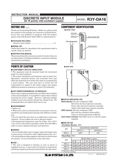
R3Y-DA16INSTRUCTION MANUALDISCRETE INPUT MODULE(Di 16 points; with excitation supply)MODEL R3Y-DA16BEFORE USE ....Thank you for choosing M-<strong>System</strong>. Before use, please checkthe contents of the package you received as outlined below.If you have any problems or questions with the product,please contact M-<strong>System</strong>’s Sales Office or representatives.■ PACKAGE INCLUDES:Discrete input module ................................................ (1)■ MODEL NO.Check that model No. described on the specification label isexactly what you ordered.■ INSTRUCTION MANUALThis manual describes necessary points of caution when youuse this product, including installation, connection and basicmaintenance procedures.COMPONENT IDENTIFICATION■ FRONT VIEWRUN LEDERR LED• Pin AssignmentB20 20A12345678910111213141516Status Indicator LEDInput ConnectorB1A1POINTS OF CAUTION■ CONFORMITY WITH EC DIRECTIVES• The equipment must be mounted inside the instrumentpanel of a metal enclosure.• The actual installation environments such as panel configurations,connected devices and connected wires mayaffect the protection level of this unit when it is integrated ina panel system. The user may have to review the CErequirements in regard to the whole system and employadditional protective measures to ensure CE conformity.■ HOT INSERTION/REMOVAL OF MODULESRemoving or replacing modules does not affect other moduleson the same backplane. It is possible to replace them withoutremoving the power supply. However, replacing multiplemodules at once may greatly change line voltage levels. Werecommend that you replace them one by one.■ ENVIRONMENT• Indoor use• When heavy dust or metal particles are present in the air,install the unit inside proper housing with sufficient ventilation.• Do not install the unit where it is subjected to continuousvibration. Do not subject the unit to physical impact.• Environmental temperature must be within -10 to +55°C(14 to 131°F) with relative humidity within 30 to 90% RH inorder to ensure adequate life span and operation.■ WIRING• Do not install cables (power supply, input and output) closeto noise sources (relay drive cable, high frequency line, etc.).• Do not bind these cables together with those in which noisesare present. Do not install them in the same duct.■ AND ....• The unit is designed to function as soon as power issupplied, however, a warm up for 10 minutes is required forsatisfying complete performance described in the data sheet.■ SIDE VIEW■SIDE DIP SW•Excitation Monitor: SW3•Read Rate: SW34321SW3ONReadRateExc.Monitor■STATUS INDICATOR LEDRUN indicator: Bi-color (red/green) LED;Red when the bus A operates normally;Green when the bus B operates normally;Amber when both buses operate normally.ERR indicator: Bi-color (red/green) LED;Red with the excitation abnormality;Green in normal operating conditions.Input status indicator: Red LED; turns on with the inputssupplied.EXCITATION MONITORSWWITH (*)WITHOUTSW3-1 OFF ONREAD RATE (≤msec)SW10(*) 1 5 20 50 70 100 200SW3-2 OFF ON OFF ON OFF ON OFF ONSW3-3 OFF OFF ON ON OFF OFF ON ONSW3-4 OFF OFF OFF OFF ON ON ON ON(*) Factory settingP. 1 / 2 EM-8963 Rev.1
R3Y-DA16INSTALLATIONUse the Installation Base (model: R3-BSx).TERMINAL CONNECTIONSConnect the unit as in the diagram below.■ DIMENSIONS mm (inch)■ CONNECTION DIAGRAM130 (5.12)27.5 (1.08) 109 (4.29)POSITIONINGGUIDEDi 1Di 2Di 3Di 4Di 5Di 620A / 20B18A / 18B16A / 16B14A / 14B12A / 12B10A / 10BBUS CONNECTORBUS ABUS B*INTERNALPOWERDi 78A / 8BDi 86A / 6BDi 919A / 19B■ INPUT CONNECTOR (40-pin)PIN NO. ASSIGNMENT PIN NO. ASSIGNMENT1A 0V 1B 0V2A 0V 2B 0V3A NC 3B NC4A NC 4B NC5A Di 16 5B Di 166A Di 8 6B Di 87A Di 15 7B Di 158A Di 7 8B Di 79A Di 14 9B Di 1410A Di 6 10B Di 611A Di 13 11B Di 1312A Di 5 12B Di 513A Di 12 13B Di 1214A Di 4 14B Di 415A Di 11 15B Di 1116A Di 3 16B Di 317A Di 10 17B Di 1018A Di 2 18B Di 219A Di 9 19B Di 920A Di 1 20B Di 1Di 10Di 11Di 12Di 13Di 14Di 15Di 16**17A / 17B15A / 15B13A / 13B11A / 13B9A / 9B7A / 7B5A / 5B4A / 4B3A / 3B2A / 2B1A / 1B* For dual redundant communication.**DO NOT connect to the pins 4A/4B or 3A/3B.M-SYSTEM WARRANTYM-<strong>System</strong> warrants such new M-<strong>System</strong> product which it manufactures to be free from defects in materials and workmanship during the 36-month period following the date that suchproduct was originally purchased if such product has been used under normal operating conditions and properly maintained, M-<strong>System</strong>'s sole liability, and purchaser's exclusive remedies,under this warranty are, at M-<strong>System</strong>'s option, the repair, replacement or refund of the purchase price of any M-<strong>System</strong> product which is defective under the terms of this warranty. Tosubmit a claim under this warranty, the purchaser must return, at its expense, the defective M-<strong>System</strong> product to the below address together with a copy of its original sales invoice.THIS IS THE ONLY WARRANTY APPLICABLE TO M-SYSTEM PRODUCT AND IS IN LIEU OF ALL OTHER WARRANTIES, EXPRESS OR IMPLIED, INCLUDING ANY IMPLIEDWARRANTIES OF MERCHANTABILITY OR FITNESS FOR A PARTICULAR PURPOSE. M-SYSTEM SHALL HAVE NO LIABILITY FOR CONSEQUENTIAL, INCIDENTAL ORSPECIAL DAMAGES OF ANY KIND WHATSOEVER.M-<strong>System</strong> Co., Ltd., 5-2-55, Minamitsumori, Nishinari-ku, Osaka 557-0063 JAPAN, Phone: (06) 6659-8201, Fax: (06) 6659-8510, E-mail: info@m-system.co.jpP. 2 / 2 EM-8963 Rev.1