invertec v205-t ac/dc & v305-t ac/dc - Lincoln Electric - documentations
invertec v205-t ac/dc & v305-t ac/dc - Lincoln Electric - documentations
invertec v205-t ac/dc & v305-t ac/dc - Lincoln Electric - documentations

You also want an ePaper? Increase the reach of your titles
YUMPU automatically turns print PDFs into web optimized ePapers that Google loves.
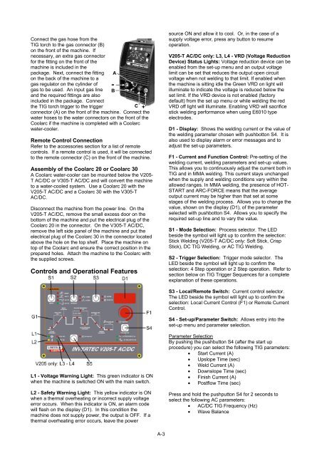
Connect the gas hose from theTIG torch to the gas connector (B)on the front of the m<strong>ac</strong>hine. Ifnecessary, an extra gas connectorfor the fitting on the front of them<strong>ac</strong>hine is included in thep<strong>ac</strong>kage. Next, connect the fittingon the b<strong>ac</strong>k of the m<strong>ac</strong>hine to agas regulator on the cylinder ofgas to be used. An input gas lineand the required fittings are alsoincluded in the p<strong>ac</strong>kage. Connectthe TIG torch trigger to the triggerconnector (A) on the front of the m<strong>ac</strong>hine. Connect thewater hoses to the water connectors on the front of theCoolarc if the m<strong>ac</strong>hine is completed with a Coolarcwater-cooler.Remote Control ConnectionRefer to the <strong>ac</strong>cessories section for a list of remotecontrols. If a remote control is used, it will be connectedto the remote connector (C) on the front of the m<strong>ac</strong>hine.Assembly of the Coolarc 20 or Coolarc 30A Coolarc water-cooler can be mounted below the V205-T AC/DC or V305-T AC/DC and will convert the m<strong>ac</strong>hineto a water-cooled system. Use a Coolarc 20 with theV205-T AC/DC and a Coolarc 30 with the V305-TAC/DC.Disconnect the m<strong>ac</strong>hine from the power line. On theV205-T AC/DC, remove the small excess door on thebottom of the m<strong>ac</strong>hine and put the electrical plug of theCoolarc 20 in the connector. On the V305-T AC/DC,remove the left side panel of the m<strong>ac</strong>hine and put theelectrical plug of the Coolarc 30 in the connector locatedabove the hole on the top shelf. Pl<strong>ac</strong>e the m<strong>ac</strong>hine ontop of the Coolarc and ensure the correct position in theprepared holes. Att<strong>ac</strong>h the m<strong>ac</strong>hine to the Coolarc withthe supplied screws.Controls and Operational Featuressource ON and allow it to cool. Or, in the case of asupply voltage error, press any button to resumeoperation.V205-T AC/DC only: L3, L4 - VRD (Voltage ReductionDevice) Status Lights: Voltage reduction device can beenabled from the set-up menu and an output voltagelimit can be set that reduces the output open circuitvoltage when not welding to that limit. If enabled whenthe m<strong>ac</strong>hine is sitting idle the Green VRD on light willilluminate to indicate the voltage is reduced below theset limit. If the VRD device is not enabled (f<strong>ac</strong>torydefault) from the set up menu or while welding the redVRD off light will illuminate. Enabling VRD will s<strong>ac</strong>rificestick welding performance when using E6010 typeelectrodes.D1 - Display: Shows the welding current or the value ofthe welding parameter chosen with pushbotton S4. It isalso used to display alarm or error messages and toadjust the set-up parameters.F1 - Current and Function Control: Pre-setting of thewelding current, welding parameters and set-up values.This allows you to continuously adjust the current both inTIG and in MMA welding. This current stays unchangedwhen the supply and welding conditions vary within theallowed ranges. In MMA welding, the presence of HOT-START and ARC-FORCE means that the averageoutput current may be higher than that set at somestages of the welding process. Allows you to change thevalue, shown on the display (D1), of the parameterselected with pushbotton S4. Allows you to specify therequired set-up line and to vary the value.S1 - Mode Selection: Process selector. The LEDbeside the symbol will light up to confirm the selection:Stick Welding (V205-T AC/DC only: Soft Stick, CrispStick), DC TIG Welding, or AC TIG Welding.S2 - Trigger Selection: Trigger mode selector. TheLED beside the symbol will light up to confirm theselection: 4 Step operation or 2 Step operation. Refer tosection below on TIG Trigger Sequences for a completeexplanation of these operations.S3 - Local/Remote Switch: Current control selector.The LED beside the symbol will light up to confirm theselection: Local Current Control (F1) or Remote CurrentControl.S4 - Set-up/Parameter Switch: Allows entry into theset-up menu and parameter selection.L1 - Voltage Warning Light: This green indicator is ONwhen the m<strong>ac</strong>hine is switched ON with the main switch.L2 - Safety Warning Light: This yellow indicator is ONwhen a thermal overheating or incorrect supply voltageerror occurs. When this indicator is ON, an alarm codewill flash on the display (D1). In this condition them<strong>ac</strong>hine does not supply power, the output is OFF. If athermal overheating error occurs, leave the powerParameter SelectionBy pushing the pushbutton S4 (after the start upprocedure) you can select the following TIG parameters:• Start Current (A)• Upslope Time (sec)• Weld Current (A)• Downslope Time (sec)• Finish Current (A)• Postflow Time (sec)Press and hold the pushputton S4 for 2 seconds toselect the following AC parameters:• AC/DC TIG Frequency (Hz)• Wave BalanceA-3