
You also want an ePaper? Increase the reach of your titles
YUMPU automatically turns print PDFs into web optimized ePapers that Google loves.
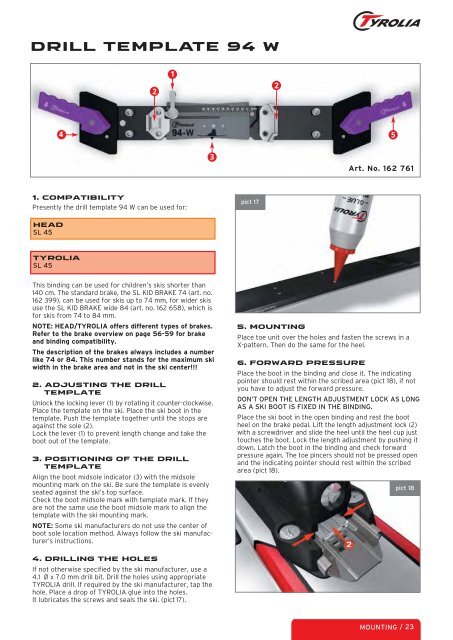
DRILL TEMPLATE 94 W<br />
1. Compatibility<br />
Presently the drill template 94 W can be used for:<br />
HEAD<br />
SL 45<br />
TYROLIA<br />
SL 45<br />
This binding can be used for children’s skis shorter than<br />
140 cm. The standard brake, the SL KID BRAKE 74 (art. no.<br />
162 399), can be used for skis up to 74 mm, for wider skis<br />
use the SL KID BRAKE wide 84 (art. no. 162 658), which is<br />
for skis from 74 to 84 mm.<br />
NOTE: HEAD/TYROLIA offers different types of brakes.<br />
Refer to the brake overview on page 56-59 for brake<br />
and binding compatibility.<br />
The description of the brakes always includes a number<br />
like 74 or 84. This number stands for the maximum ski<br />
width in the brake area and not in the ski center!!!<br />
2. ADJUSTING THE DRILL<br />
TEMPLATE<br />
Unlock the locking lever (1) by rotating it counter-clockwise.<br />
Place the template on the ski. Place the ski boot in the<br />
template. Push the template together until the stops are<br />
against the sole (2).<br />
Lock the lever (1) to prevent length change and take the<br />
boot out of the template.<br />
3. POSITIONING OF THE DRILL<br />
TEMPLATE<br />
Align the boot midsole indicator (3) with the midsole<br />
mounting mark on the ski. Be sure the template is evenly<br />
seated against the ski’s top surface.<br />
Check the boot midsole mark with template mark. If they<br />
are not the same use the boot midsole mark to align the<br />
template with the ski mounting mark.<br />
NOTE: Some ski manufacturers do not use the center of<br />
boot sole location method. Always follow the ski manufacturer’s<br />
instructions.<br />
4. DRILLING THE HOLES<br />
If not otherwise specified by the ski manufacturer, use a<br />
4.1 Ø x 7.0 mm drill bit. Drill the holes using appropriate<br />
TYROLIA drill. If required by the ski manufacturer, tap the<br />
hole. Place a drop of TYROLIA glue into the holes.<br />
It lubricates the screws and seals the ski. (pict 17).<br />
2<br />
1<br />
4 5<br />
3<br />
pict 17<br />
2<br />
Art. No. 162 761<br />
5. MOUNTING<br />
Place toe unit over the holes and fasten the screws in a<br />
X-pattern. Then do the same for the heel.<br />
6. FORWARD PRESSURE<br />
Place the boot in the binding and close it. The indicating<br />
pointer should rest within the scribed area (pict 18), if not<br />
you have to adjust the forward pressure.<br />
DON’T OPEN THE LENGTH ADJUSTMENT LOCK AS LONG<br />
AS A SKI BOOT IS FIXED IN THE BINDING.<br />
Place the ski boot in the open binding and rest the boot<br />
heel on the brake pedal. Lift the length adjustment lock (2)<br />
with a screwdriver and slide the heel until the heel cup just<br />
touches the boot. Lock the length adjustment by pushing it<br />
down. Latch the boot in the binding and check forward<br />
pressure again. The toe pincers should not be pressed open<br />
and the indicating pointer should rest within the scribed<br />
area (pict 18).<br />
pict 18<br />
MOUNTING / 23