FHV/ FHVT HVS/ HVST - Walter Roller GmbH & Co.
FHV/ FHVT HVS/ HVST - Walter Roller GmbH & Co.
FHV/ FHVT HVS/ HVST - Walter Roller GmbH & Co.

Create successful ePaper yourself
Turn your PDF publications into a flip-book with our unique Google optimized e-Paper software.
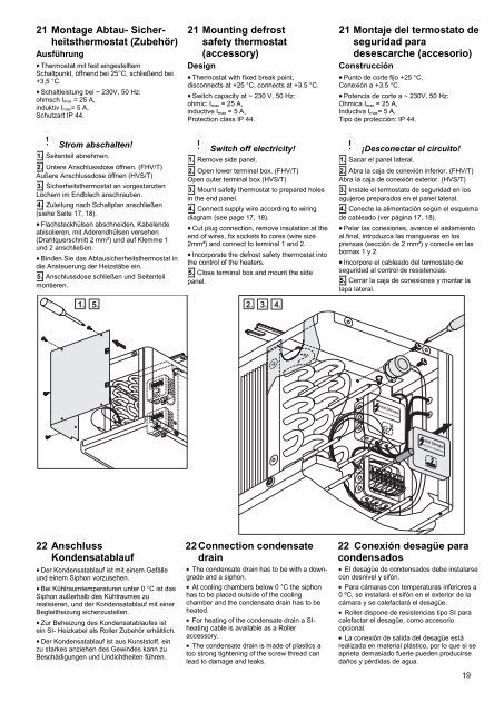
21 Montage Abtau- Sicherheitsthermostat<br />
(Zubehör)<br />
Ausführung<br />
Thermostat mit fest eingestelltem<br />
Schaltpunkt, öffnend bei 25°C, schließend bei<br />
+3,5 °C.<br />
Schaltleistung bei ~ 230V, 50 Hz:<br />
ohmsch Imax = 25 A,<br />
induktiv Imax= 5 A,<br />
Schutzart IP 44.<br />
Strom abschalten!<br />
1. Seitenteil abnehmen.<br />
2. Untere Anschlussdose öffnen. (<strong>FHV</strong>/T)<br />
Äußere Anschlussdose öffnen (<strong>HVS</strong>/T)<br />
3. Sicherheitsthermostat an vorgestanzten<br />
Löchern im Endblech anschrauben.<br />
4. Zuleitung nach Schaltplan anschließen<br />
(siehe Seite 17, 18).<br />
Flachsteckhülsen abschneiden, Kabelende<br />
abisolieren, mit Aderendhülsen versehen<br />
(Drahtquerschnitt 2 mm²) und auf Klemme 1<br />
und 2 anschließen.<br />
Binden Sie das Abtausicherheitsthermostat in<br />
die Ansteuerung der Heizstäbe ein.<br />
5. Anschlussdose schließen und Seitenteil<br />
montieren.<br />
22 Anschluss<br />
Kondensatablauf<br />
Der Kondensatablauf ist mit einem Gefälle<br />
und einem Siphon vorzusehen.<br />
Bei Kühlraumtemperaturen unter 0 °C ist das<br />
Siphon außerhalb des Kühlraumes zu<br />
realisieren, und der Kondensatablauf mit einer<br />
Begleitheizung sicherzustellen.<br />
Zur Beheizung des Kondensatablaufes ist<br />
ein SI- Heizkabel als <strong>Roller</strong> Zubehör erhältlich.<br />
Der Kondensatablauf ist aus Kunststoff, ein<br />
zu starkes anziehen des Gewindes kann zu<br />
Beschädigungen und Undichtheiten führen.<br />
21 Mounting defrost<br />
safety thermostat<br />
(accessory)<br />
Design<br />
Thermostat with fixed break point,<br />
disconnects at +25 °C, connects at +3.5 °C.<br />
Switch capacity at ~ 230 V, 50 Hz:<br />
ohmic: Imax = 25 A,<br />
inductive Imax = 5 A,<br />
Protection class IP 44.<br />
Switch off electricity!<br />
1. Remove side panel.<br />
2. Open lower terminal box. (<strong>FHV</strong>/T)<br />
Open outer terminal box (<strong>HVS</strong>/T)<br />
3. Mount safety thermostat to prepared holes<br />
in the end panel.<br />
4. <strong>Co</strong>nnect supply wire according to wiring<br />
diagram (see page 17, 18).<br />
Cut plug connection, remove insulation at the<br />
end of wires, fix sockets to cores (wire size<br />
2mm²) and connect to terminal 1 and 2.<br />
Incorporate the defrost safety thermostat into<br />
the control of the heaters.<br />
5. Close terminal box and mount the side<br />
panel.<br />
22 <strong>Co</strong>nnection condensate<br />
drain<br />
The condensate drain has to be with a downgrade<br />
and a siphon.<br />
At cooling chambers below 0 °C the siphon<br />
has to be placed outside of the cooling<br />
chamber and the condensate drain has to be<br />
heated.<br />
For heating of the condensate drain a SI-<br />
heating cable is available as a <strong>Roller</strong><br />
accessory.<br />
The condensate drain is made of plastics a<br />
too strong tightening of the screw thread can<br />
lead to damage and leaks.<br />
21 Montaje del termostato de<br />
seguridad para<br />
desescarche (accesorio)<br />
<strong>Co</strong>nstrucción<br />
Punto de corte fijo +25 °C,<br />
<strong>Co</strong>nexión a +3,5 °C.<br />
Potencia de corte a ~ 230V, 50 Hz:<br />
Ohmica Imax = 25 A,<br />
Inductiva Imax= 5 A,<br />
Tipo de protección: IP 44.<br />
¡Desconectar el circuito!<br />
1. Sacar el panel lateral.<br />
2. Abra la caja de conexión inferior. (<strong>FHV</strong>/T)<br />
Abra la caja de conexión exterior. (<strong>HVS</strong>/T)<br />
3. Instale el termostato de seguridad en los<br />
agujeros preparados en el panel lateral.<br />
4. <strong>Co</strong>necte la alimentación según el esquema<br />
de cableado (ver página 17, 18).<br />
Pelar las conexiones, avance el aislamiento<br />
al final, introduzca las mangueras en los<br />
prensas (sección de 2 mm²) y conecte en las<br />
bornas 1 y 2.<br />
Incorpore el cableado del termostato de<br />
seguridad al control de resistencias.<br />
5. Cerrar la caja de conexiones y montar la<br />
tapa lateral.<br />
22 <strong>Co</strong>nexión desagüe para<br />
condensados<br />
El desagüe de condensados debe instalarse<br />
con desnivel y sifón.<br />
Para cámaras con temperaturas inferiores a<br />
0 ºC, se instalará el sifón en el exterior de la<br />
cámara y se calefactará el desagüe.<br />
<strong>Roller</strong> dispone de resistencias tipo SI para<br />
calefactar el desagüe, como accesorio<br />
opcional.<br />
La conexión de salida del desagüe está<br />
realizada en material plástico, por lo que si se<br />
aprieta demasiado fuerte pueden producirse<br />
daños y pérdidas de agua.<br />
19