Roof Fans – with direct drive
Roof Fans – with direct drive
Roof Fans – with direct drive

Erfolgreiche ePaper selbst erstellen
Machen Sie aus Ihren PDF Publikationen ein blätterbares Flipbook mit unserer einzigartigen Google optimierten e-Paper Software.
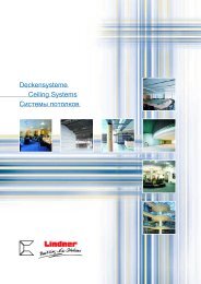
V<br />
400<br />
230<br />
270<br />
50 87 Hz<br />
Dachventilatoren<br />
Beschreibung<br />
Elektrischer Anschluss<br />
Alle Dachventilatoren werden anschlussfertig geliefert.<br />
Der elektrische Anschluss erfolgt gemäß der beigefügten<br />
Betriebsanleitung unter Beachtung der jeweils<br />
gültigen örtlichen Vorschriften und Richtlinien. Die elektrische<br />
Zuleitung erfolgt durch die Kabeldurchführung<br />
im Ventilatorgrundrahmen zum Klemmenkasten. Jedem<br />
Ventilator ist ein Anschlussschema beigefügt.<br />
Die aktuelle Schaltbild-Zuordnung finden Sie auch online<br />
unter:<br />
www.nicotra-gebhardt.com.<br />
RBA fanbox bei Frequenzumrichterbetrieb<br />
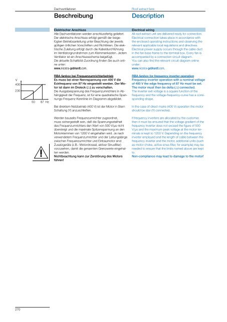
Es muss bei einer Nennspannung von 400 V die<br />
Eckfrequenz von 87 Hz eingestellt werden. Der Motor<br />
ist dann im Dreieck (g) zu verschalten.<br />
Die Ausgabespannung des Frequenzumrichters in Abhängigkeit<br />
der Frequenz, ist für eine quadratische Spannungs-Frequenz-Kennlinie<br />
im Diagramm abgebildet.<br />
Bei direktem Netzbetrieb (400 V) ist der Motor in Stern<br />
Schaltung (Y) anzuschließen.<br />
Werden bauseits Frequenzumrichter zugeordnet,<br />
muss sichergestellt sein, daß die Spannungssteilheit<br />
des Frequenzumrichters den Wert von 500 V/µs nicht<br />
übersteigt und die maximale Spitzenspannung an den<br />
Motorklemmen von 1200 V eingehalten wird. Je nach<br />
verwendetem Frequenzumrichter und der Leitungslänge<br />
zwischen Frequenzumrichter und Einbaumotor sind<br />
Zusatzgeräte (z.B.: Motordrossel, aktiver Sinusfilter)<br />
vorzusehen, damit die genannten Grenzwerte eingehalten<br />
werden.<br />
Nichtbeachtung kann zur Zerstörung des Motors<br />
führen!<br />
<strong>Roof</strong> extract fans<br />
Description<br />
Electrical wiring<br />
All roof extract unit are delivered ready for connection.<br />
Electrical connection takes place in accordance <strong>with</strong><br />
the enclosed operating instructions and observing the<br />
relevant applicable local regulations and <strong>direct</strong>ives.<br />
Electrical power supply occurs through the cable duct<br />
in the fan base frame to the terminal box. Every fan is<br />
accompanied by a connection circuit diagram.<br />
You can also find the relevant circuit diagram online<br />
under:<br />
www.nicotra-gebhardt.com.<br />
RBA fanbox for frequency inverter operation<br />
Frequency inverter operation <strong>with</strong> a nominal voltage<br />
of 400 V the edge frequency of 87 Hz must be set.<br />
The motor must then be delta (g) connected.<br />
The inverter exit voltage is a square function of the<br />
frequency and the voltage-frequency-curve has a corresponding<br />
shape.<br />
In the case of <strong>direct</strong> mains (400 V) operation the motor<br />
should be star (Y) connected.<br />
If frequency inverters are allocated by the customer,<br />
then it must be ensured that the voltage gradient of the<br />
frequency inverter does not exceed the figure of 500<br />
V/µs and the maximum peak voltage at the motor terminals<br />
is kept to 1200 V. Depending on the frequency<br />
inverter employed and the length of cable between the<br />
frequency inverter and the motor, additional units (such<br />
as motor choke, active sinus filter, for example) may be<br />
needed to ensure that the limits named above are kept<br />
to.<br />
Non-compliance may lead to damage to the motor!