Roof Fans – with direct drive
Roof Fans – with direct drive
Roof Fans – with direct drive

Erfolgreiche ePaper selbst erstellen
Machen Sie aus Ihren PDF Publikationen ein blätterbares Flipbook mit unserer einzigartigen Google optimierten e-Paper Software.
272<br />
Dachventilatoren<br />
Beschreibung<br />
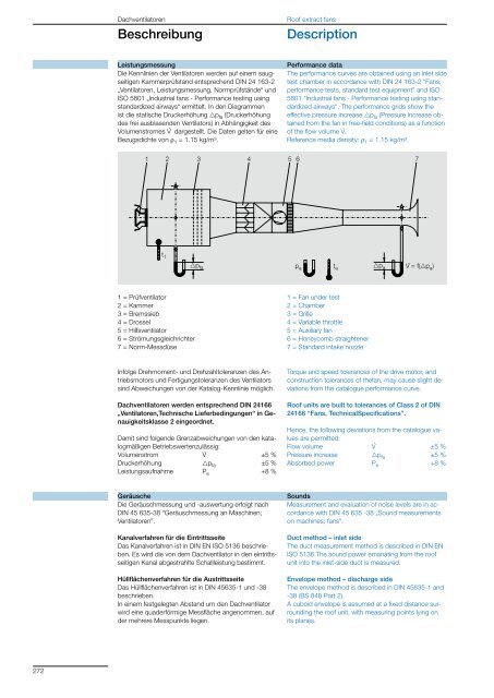
Die Kennlinien der Ventilatoren werden auf einem saugseitigen<br />
Kammerprüfstand entsprechend DIN 24 163-2<br />
„Ventilatoren, Leistungsmessung, Normprüfstände“ und<br />
ISO 5801 „Industrial fans - Performance testing using<br />
standardized airways“ ermittelt. In den Diagrammen<br />
ist die statische Druckerhöhung gpfa (Druckerhöhung<br />
des frei ausblasenden Ventilators) in Abhängigkeit des<br />
Volumenstromes V . Leistungsmessung<br />
dargestellt. Die Daten gelten für eine<br />
Bezugsdichte von r1 = 1.15 kg/m³.<br />
1 2 3 4<br />
5 6<br />
7<br />
t 1<br />
1 = Prüfventilator<br />
2 = Kammer<br />
3 = Bremssieb<br />
4 = Drossel<br />
5 = Hilfsventilator<br />
6 = Strömungsgleichrichter<br />
7 = Norm-Messdüse<br />
The performance curves are obtained using an inlet side<br />
test chamber in accordance <strong>with</strong> DIN 24 163-2 “<strong>Fans</strong>,<br />
performance tests, standard test equipment” and ISO<br />
5801 “Industrial fans - Performance testing using standardized<br />
airways“. The performance grids show the<br />
effective pressure increase gpfa (Pressure increase obtained<br />
from the fan in free-field conditions) as a function<br />
of the flow volume V . Performance data<br />
.<br />
Reference media density: r1 = 1.15 kg/m³.<br />
pfa pa V . pa ta = f(pa )<br />
Infolge Drehmoment- und Drehzahltoleranzen des Antriebsmotors<br />
und Fertigungstoleranzen des Ventilators<br />
sind Abweichungen von der Katalog-Kennlinie möglich.<br />
Dachventilatoren werden entsprechend DIN 24166<br />
„Ventilatoren,Technische Lieferbedingungen“ in Genauigkeitsklasse<br />
2 eingeordnet.<br />
Damit sind folgende Grenzabweichungen von den katalogmäßigen<br />
Betriebswertenzulässig:<br />
Volumenstrom V . ±5 %<br />
Druckerhöhung gp fa ±5 %<br />
Leistungsaufnahme P e +8 %<br />
Geräusche<br />
Die Geräuschmessung und -auswertung erfolgt nach<br />
DIN 45 635-38 “Geräuschmessung an Maschinen;<br />
Ventilatoren”.<br />
Kanalverfahren für die Eintrittsseite<br />
Das Kanalverfahren ist in DIN EN ISO 5136 beschrieben.<br />
Es wird die von dem Dachventilator in den eintrittsseitigen<br />
Kanal abgestrahlte Schallleistung bestimmt.<br />
Hüllflächenverfahren für die Austrittsseite<br />
Das Hüllflächenverfahren ist in DIN 45635-1 und -38<br />
beschrieben.<br />
In einem festgelegten Abstand um den Dachventilator<br />
wird eine quaderförmige Messfläche angenommen, auf<br />
der mehrere Messpunkte liegen.<br />
<strong>Roof</strong> extract fans<br />
Description<br />
1 = Fan under test<br />
2 = Chamber<br />
3 = Grille<br />
4 = Variable throttle<br />
5 = Auxiliary fan<br />
6 = Honeycomb straightener<br />
7 = Standard intake nozzle<br />
Torque and speed tolerances of the <strong>drive</strong> motor, and<br />
construction tolerances of thefan, may cause slight deviations<br />
from the catalogue performance curve.<br />
<strong>Roof</strong> units are built to tolerances of Class 2 of DIN<br />
24166 “<strong>Fans</strong>, TechnicalSpecifications”.<br />
Hence, the following deviations from the catalogue values<br />
are permitted:<br />
Flow volume V . ±5 %<br />
Pressure increase gp fa ±5 %<br />
Absorbed power P e +8 %<br />
Sounds<br />
Measurement and evaluation of noise levels are in accordance<br />
<strong>with</strong> DIN 45 635 -38 „Sound measurements<br />
on machines; fans“.<br />
Duct method <strong>–</strong> inlet side<br />
The duct measurement method is described in DIN EN<br />
ISO 5136.The sound power emanating from the roof<br />
unit into the inlet-side duct is measured.<br />
Envelope method <strong>–</strong> discharge side<br />
The envelope method is described in DIN 45635-1 and<br />
-38 (BS 848 Part 2).<br />
A cuboid envelope is assumed at a fixed distance surrounding<br />
the roof unit, <strong>with</strong> measuring points lying on<br />
its planes.