Roof Fans – with direct drive
Roof Fans – with direct drive
Roof Fans – with direct drive

Erfolgreiche ePaper selbst erstellen
Machen Sie aus Ihren PDF Publikationen ein blätterbares Flipbook mit unserer einzigartigen Google optimierten e-Paper Software.
Dachventilatoren<br />
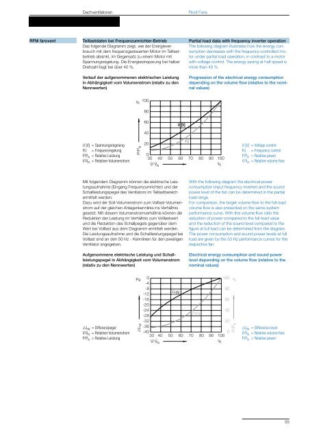
RFM farovent Teillastdaten bei Frequenzumrichter-Betrieb<br />
Partial load data <strong>with</strong> frequency inverter operation<br />
Das folgende Diagramm zeigt, wie der Energieverbrauch<br />
mit dem frequenzgesteuerten Motor im Teillastbetrieb<br />
absinkt, im Gegensatz zu einem Motor mit<br />
Spannungsregelung. Die Energieeinsparung bei halber<br />
Drehzahl liegt bei über 40 %.<br />
Verlauf der aufgenommenen elektrischen Leistung<br />
in Abhängigkeit vom Volumenstrom (relativ zu den<br />
Nennwerten)<br />
U [V] = Spannungsregelung<br />
FU = Frequenzregelung<br />
P/PN = Relative Leistung<br />
V . /V . N = Relativer Volumenstrom<br />
%<br />
100<br />
P/P N<br />
Pa<br />
L W<br />
80<br />
60<br />
40<br />
20<br />
U [V]<br />
Mit folgendem Diagramm können die elektrische Leistungsaufnahme<br />
(Eingang Frequenzumrichter) und der<br />
Schallleistungspegel des Ventilators im Teillastbereich<br />
ermittelt werden.<br />
Dazu wird der SollVolumenstrom zum VolllastVolumenstrom<br />
auf der gleichen Anlagenkennlinie ins Verhältnis<br />
gesetzt. Mit diesem Volumenstromverhältnis können die<br />
Reduktion der Leistung im Verhältnis zum Volllastwert<br />
und die Reduktion des Schallpegels gegenüber dem<br />
Wert bei Volllast aus dem Diagramm ermittelt werden.<br />
Die Leistungsaufnahme und die Schallleistungspegel bei<br />
Volllast sind an den 50 Hz Kennlinien für den jeweiligen<br />
Ventilator angegeben.<br />
Aufgenommene elektrische Leistung und Schallleistungspegel<br />
in Abhängigkeit vom Volumenstrom<br />
(relativ zu den Nennwerten)<br />
LW = Differenzpegel<br />
V . /V . N = Relativer Volumenstrom<br />
P/PN = Relative Leistung<br />
FU<br />
<strong>Roof</strong> <strong>Fans</strong><br />
0<br />
30 40<br />
V<br />
50 60 70 80 90 100<br />
· / V · N<br />
%<br />
0<br />
-4<br />
100<br />
-8<br />
-12<br />
80<br />
-16<br />
-20<br />
60<br />
-24<br />
-28<br />
40<br />
-32<br />
-36<br />
20<br />
-40<br />
30 40<br />
V<br />
50 60 70 80 90 100<br />
%<br />
0<br />
· / V · LW P/PN N<br />
The following diagram illustrates how the energy consumption<br />
decreases <strong>with</strong> the frequencycontrolled motor<br />
under partial load operation, in contrast to a motor<br />
<strong>with</strong> voltage control. The energy saving at half speed is<br />
more than 40 %.<br />
Progression of the electrical energy consumption<br />
depending on the volume flow (relative to the nominal<br />
values)<br />
%<br />
P/P N<br />
U [V] = Voltage control<br />
FU = Frequency control<br />
P/PN = Relative power<br />
V . /V . N = Relative volume flow<br />
With the following diagram the electrical power<br />
consumption (input frequency inverter) and the sound<br />
power level of the fan can be determined in the partial<br />
load range.<br />
For comparison, the target volume flow to the fullload<br />
volume flow is also presented on the same system<br />
performance curve. With this volume flow ratio the<br />
reduction of power compared to the fullload value<br />
and the reduction of the sound level compared to the<br />
figure at full load can be determined from the diagram.<br />
The power consumption and sound power levels at full<br />
load are given by the 50 Hz performance curves for the<br />
respective fan.<br />
Electrical energy consumption and sound power<br />
level depending on the volume flow (relative to the<br />
nominal values)<br />
LW = Difference level<br />
V . /V . N = Relative volume flow<br />
P/PN = Relative power<br />
55