Roof Fans – with direct drive
Roof Fans – with direct drive
Roof Fans – with direct drive

Erfolgreiche ePaper selbst erstellen
Machen Sie aus Ihren PDF Publikationen ein blätterbares Flipbook mit unserer einzigartigen Google optimierten e-Paper Software.
L<br />
30<br />
dB<br />
20<br />
10<br />
r<br />
a<br />
b<br />
1 5 10<br />
m<br />
r<br />
Dachventilatoren<br />
Beschreibung<br />
L p8<br />
p a<br />
<strong>Roof</strong> extract fans<br />
Description<br />
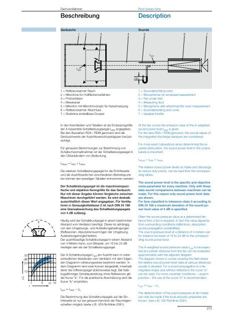
Geräusche<br />
Sounds<br />
1 2 3 4 5<br />
6<br />
7<br />
1 = Reflexionsarmer Raum<br />
2 = Mikrofone für Hüllflächenverfahren<br />
3 = Prüfventilator<br />
4 = Messkanal<br />
5 = Mikrofon mit Mikrofonvorsatz für Kanalmessung<br />
6 = Reflexionsarmer Abschluss<br />
7 = Stufenlos einstellbare Drossel<br />
In den Kennfeldern und Tabellen ist als Emissionsgröße<br />
der A-bewertete Schallleistungspegel L WA angegeben.<br />
Bei den Baureihen RDA / RDM genovent sind die<br />
Geräuschwerte der Austrittsverschlussklappen berücksichtigt.<br />
Für genauere Berechnungen zur Bestimmung von<br />
Schallschutzmaßnahmen ist der Schallleistungspegel in<br />
den Oktavbändern von Bedeutung.<br />
L Wokt = L WA + L Wrel<br />
Die relativen Schallleistungspegel für die Eintrittsseite<br />
und die Austrittsseite bei verschiedenen Betriebspunkten<br />
können den jeweiligen Tabellen entnommen werden.<br />
Der Schallleistungspegel ist die maschinenspezifische<br />
und objektive Kenngröße für das Geräusch.<br />
Nur mit dieser Angabe können Vergleiche zwischen<br />
Maschinen durchgeführt werden. Es wird deshalb<br />
ausschließlich dieser Wert angegeben. Für Ventilatoren<br />
in Genauigkeitsklasse 2 ist nach DIN 24 166<br />
eine Grenzabweichung des Schallleistungspegels<br />
von 4 dB zulässig.<br />
Häufig wird der Schalldruckpegel in einem bestimmten<br />
Abstand vom Ventilator benötigt. Dieser ist abhängig<br />
von den Umgebungs- und Aufstellungsbedingungen<br />
(Reflexionen, Absorptionsvermögen der Umgebung,<br />
Ausbreitungsmöglichkeiten).<br />
Der austrittsseitige Schalldruckpegel in einem Abstand<br />
von 4 Metern kann, zum Beispiel, um 16 bis 23 dB<br />
niedriger sein als der Schallleistungspegel.<br />
Der A-Schalldruckpegel L pA am Austritt kann in unterschiedlichen<br />
Abständen vom Ventilator mit dem folgenden<br />
Diagramm näherungsweise bestimmt werden. In<br />
dem Diagramm sind zwei Kurven dargestellt, innerhalb<br />
derer der Differenzpegel üblicherweise liegt. Bei halbkugelförmiger<br />
Schallausbreitung ohne Reflexionen gilt<br />
die Kurve “a”. Für die praktische Abschätzung wird die<br />
Kurve “b” empfohlen.<br />
L pA P L WA <strong>–</strong> g L<br />
Die Bestimmung des Schalldruckpegels auf der Eintrittsseite<br />
ist nur bei genauer Kenntnis der Raumeigenschaften<br />
möglich (siehe z.B. VDI-Richtlinie 2081).<br />
L p3<br />
1 = Soundabsorbing room<br />
2 = Microphones for envelopemeasurement<br />
3 = Fan under test<br />
4 = Measuring duct<br />
5 = Microphone <strong>with</strong> attachmentfor duct measurement<br />
6 = Soundabsorbing end cover<br />
7 = Variable throttle<br />
At the fan curves the emission value of the A-weighted<br />
sound power level L WA is given.<br />
For the fans RDA / RDM genovent, the sound values of<br />
the integrated discharge dampers are considered.<br />
For more exact calculations when determining the required<br />
attenuation, the sound power level in the octave<br />
bands is important.<br />
L Wokt = L WA + L Wrel<br />
The relative sound power levels at intake and discharge,<br />
at various duty points, can be read from the corresponding<br />
tables.<br />
The sound power level is the specific and objective<br />
noise parameter for every machine. Only <strong>with</strong> these<br />
data sound comparisons between machines can be<br />
made. For this reason only sound power level data<br />
are shown.<br />
For fans classified to tolerance class 2 according to<br />
DIN 24 166 a maximum deviation of the sound power<br />
level value of 4 dB is specified.<br />
Often the sound pressure value at a determined distance<br />
from a fan is required. In fact this value depends<br />
from surrounding conditions (reflections, absorption,<br />
sound propagation possibilities).<br />
The sound pressure level at a distance of 4 meters can<br />
for instance be lower of 16 to 23 dB to the corresponding<br />
sound power level.<br />
The A-weighted sound pressure value L pA to be expected<br />
at a certain distance from the fan can be evaluated<br />
approximately <strong>with</strong> the adjacent diagram.<br />
The diagram shows 2 curves covering the field where<br />
the relative sound power level data at various distances<br />
usually is situated. For a sound propagation in a hemisphere<br />
shape and <strong>with</strong>out reflections the curve “a”<br />
can be used. For more uncertain conditions <strong>–</strong> usual in<br />
practice <strong>–</strong> the use of the curve “b” is recommended.<br />
L pA P L WA <strong>–</strong> g L<br />
The determination of the sound pressure at fan intake<br />
can only be made if the local acoustic properties are<br />
known. (see z.B. VDI-Richtlinie 2081).<br />
273