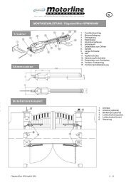
Mechanical & electrical Installation SCS200 - Nothnagel
Mechanical & electrical Installation SCS200 - Nothnagel
Mechanical & electrical Installation SCS200 - Nothnagel

Sie wollen auch ein ePaper? Erhöhen Sie die Reichweite Ihrer Titel.
YUMPU macht aus Druck-PDFs automatisch weboptimierte ePaper, die Google liebt.
PLEASE START BY READING THESE IMPORTANT SAFETY RULES • SAVE THESE INSTRUCTIONS<br />
This safety alert symbol means "Caution" - failure to comply with such an instruction involves risk of personal injury or<br />
damage to property. Please read these warnings carefully.<br />
This gate drive mechanism is designed and tested to offer appropriately safe service provided it is installed and operated in<br />
strict accordance with the following safety rules.<br />
Incorrect installation and/or failure to comply with the following instructions may result in serious personal injury or property<br />
damage.<br />
When using tools and small parts to install or carry<br />
out repair work on a gate exercise caution and do not<br />
wear rings, watches or loose clothing.<br />
<strong>Installation</strong> and wiring must be in compliance with<br />
your local building and <strong>electrical</strong> installation codes.<br />
Power cables must only be connected to a properly<br />
earthed supply.<br />
Any entrapment possibility by the moving wing<br />
between wing & walls must be secured with safety<br />
edges or IR-sensors.<br />
Please remove any locks fitted to the gate in order to<br />
prevent damage to the gate.<br />
After the installation a final test of the full function of<br />
the system and the full function of the safety devices<br />
must be done.<br />
This drive cannot be used with a gate incorporating a<br />
wicket door unless the drive cannot be operated with<br />
the wicket door open.<br />
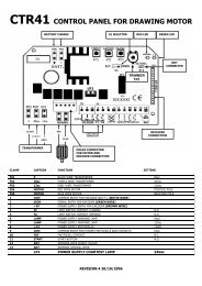
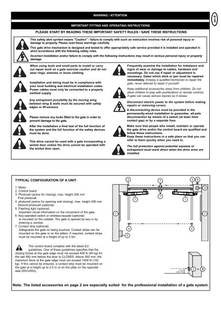
TYPICAL CONFIGURATION OF A UNIT:<br />
1. Motor<br />
2. Control board<br />
3. Photocell (active for closing), max. height 200 mm<br />
First photocell.<br />
4. photocell (active for opening and closing), max. height 200 mm<br />
Second photocell (optional).<br />
5. Flashing light (optional)<br />
Important visual information on the movement of the gate.<br />
6. Key-operated switch or wireless keypad (optional)<br />
Is mounted on the outside. The gate is opened by key or by<br />
entering a number.<br />
7. Contact strip (optional)<br />
Safeguards the gate on being touched. Contact strips can be<br />
mounted on the gate or on the pillars. If required, contact strips<br />
must be mounted at a height of up to 2.5m.<br />
The control board complies with the latest EU<br />
guidelines. One of these guidelines specifies that the<br />
closing forces at the gate edge must not exceed 400 N (40 kg) for<br />
the last 500 mm before the door is CLOSED. Above 500 mm, the<br />
maximum force at the gate edge must not exceed 1400 N (140<br />
kg). If this cannot be ensured, a contact strip must be mounted on<br />
the gate at a height up to 2.5 m or on the pillar on the opposite<br />
side (EN12453).<br />
WARNING / ATTENTION<br />
IMPORTANT FITTING AND OPERATING INSTRUCTIONS<br />
Frequently examine the installation for imbalance and<br />
signs of wear or damage to cables, hardware and<br />
mountings. Do not use if repair or adjustment is<br />
necessary. Gates which stick or jam must be repaired<br />
immediately. Employ a qualified technician to repair the<br />
gate, never attempt to repair it yourself.<br />
Keep additional accessories away from children. Do not<br />
allow children to play with pushbuttons or remote controls.<br />
A gate can cause serious injuries as it closes.<br />
Disconnect electric power to the system before making<br />
repairs or removing covers.<br />
A disconnecting device must be provided in the<br />
permanently-wired installation to guarantee all-pole<br />
disconnection by means of a switch (at least 3mm<br />
contact gap) or by a separate fuse.<br />
Make sure that people who install, maintain or operate<br />
the gate drive and/or the control board are qualified and<br />
follow these instructions.<br />
Keep these instructions in a safe place so that you can<br />
refer to them quickly when you need to.<br />
The full protection against potential squeeze or<br />
entrapment must work direct when the drive arms are<br />
installed.<br />
Note: The listed accessories on page 2 are especially suited for the professional installation of a gate system.<br />
+<br />
4<br />
en-6