Mechanical & electrical Installation SCS200 - Nothnagel
Mechanical & electrical Installation SCS200 - Nothnagel
Mechanical & electrical Installation SCS200 - Nothnagel

Erfolgreiche ePaper selbst erstellen
Machen Sie aus Ihren PDF Publikationen ein blätterbares Flipbook mit unserer einzigartigen Google optimierten e-Paper Software.
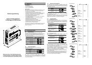
INDICATION OF THE DIAGNOSIS LED<br />
Indication Description Remedy<br />
1x blinking Motor 1 has insufficient connection to control board Green or white cable not wired or badly connected Check<br />
terminals precisely. Consider wire lengths<br />
2x blinking Motor 2 has insufficient connection to control board Refer to 1x blinking<br />
3x blinking Limits for motor 2 have not been accepted A: Open gate wide enough when programming the travel (50%<br />
A: After or during programming travel: Wing 1 did not over maximum)<br />
open wide enough and did not meet the integrated B: Check terminals precisely. Consider wire lengths<br />
passpoint which is located inside the operator halfway<br />
above the spindle.<br />
B: Motorcables have insufficient connection to contol board<br />
Yellow or white cable not wired or badly connected<br />
4x blinking Limits for motor 1 have not been accepted Refer to 3x blinking<br />
5x blinking Travel has not been programmed Repeat programming travel<br />
The process of programming has been interrupted<br />
6x blinking Force to operate the gate is too high<br />
A: Gate is out of order A: Repair gate<br />
B: Gate is rough-running B: Check if gate can be easily moved<br />
C: Gate stopped through windload C: Do not operate gate by windstorm<br />
D: Reprogram travel to achieve sufficient level of fo<br />
7x blinking Photocells 1 block installation<br />
A: Object blocks photocells A: Remove object<br />
B: Alignment of the lenses is incorrect B: Check alignment<br />
C: Power supply to photocells is insufficient C: Check cable widths and contacts<br />
8x blinking Photocells 2 block installation Refer to 7x blinking<br />
9x blinking Emergency stop switch blocks installation A: Check wiring<br />
B: Check basic setting of control board (Jumpers)<br />
10xblinking Safety edge blocks installation<br />
A: Object obstructs safety edge A: Remove object<br />
B: Defective safety edge B: Check wiring. Check resistor 8.2KOhms<br />
C: Power too low or broken wire in supply C: Check basic setting of control board (Jumpers)<br />
11xblinking Power supply to control board is too low<br />
A: Defective supply 230V or malfunctioning contact A: Check electric contact<br />
B: Broken wire in supply cable (copper cable) B: Check by electrician<br />
C: The battery (accessory) to operate the gate whilst C: Allow battery to charge 24 hours<br />
power failure is dead.<br />
12xblinking EEPROM Fault<br />
Power up failed Replace contol board<br />
en-14