Mechanical & electrical Installation SCS200 - Nothnagel
Mechanical & electrical Installation SCS200 - Nothnagel
Mechanical & electrical Installation SCS200 - Nothnagel

Sie wollen auch ein ePaper? Erhöhen Sie die Reichweite Ihrer Titel.
YUMPU macht aus Druck-PDFs automatisch weboptimierte ePaper, die Google liebt.
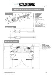
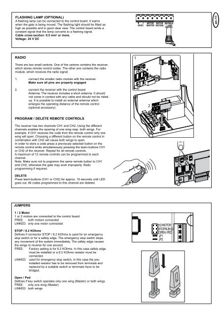
FLASHING LAMP (OPTIONAL)<br />
A flashing lamp can be connected to the control board. It warns<br />
when the gate is being moved. The flashing light should be fitted as<br />
high as possible and in good clear view. The control board emits a<br />
constant signal that the lamp converts to a flashing signal.<br />
Cable cross-section: 0.5 mm 2 or more.<br />
Voltage: 24 V DC<br />
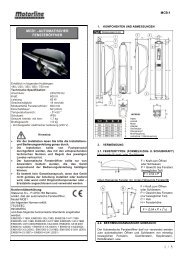
RADIO<br />
There are two small cartons. One of the cartons contains the receiver,<br />
which stores remote control codes. The other one contains the radio<br />
module, which receives the radio signal.<br />
1. connect the smaller radio module with the receiver<br />
Make sure all pins are properly engaged<br />
2. connect the receiver with the control board<br />
Antenna: The receiver includes a short antenna. It should<br />
not come in contact with any cable and should not be rolled<br />
up. It is possible to install an external antenna which<br />
enlarges the operating distance of the remote control<br />
(optional accessory).<br />
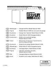
PROGRAM / DELETE REMOTE CONTROLS<br />
The receiver has two channels CH1 and CH2. Using the different<br />
channels enables the opening of one wing resp. both wings. For<br />
example, if CH1 receives the code from the remote control only one<br />
wing will open. Choosing a different button on the remote control in<br />
combination with CH2 will cause both wings to open.<br />
In order to store a code press a previously selected button on the<br />
remote control while simultaneously pressing the learn-buttons CH1<br />
or CH2 of the receiver. Repeat for all remote controls.<br />
A maximum of 12 remote controls can be programmed to each<br />
channel.<br />
Note: Make sure not to pogramm the same remote button to CH1<br />
and CH2, otherwise the gate may work improperly. Redo<br />
programming if required.<br />
DELETE<br />
Press learn-buttons (CH1 or CH2) for approx. 10 seconds until LED<br />
goes out. All codes programmed to this channel are deleted.<br />
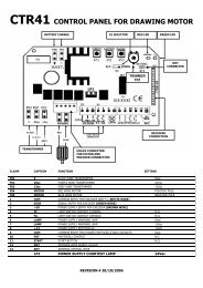
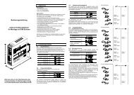
JUMPERS<br />
1 / 2 Motor<br />
1 or 2 motors are connected to the control board.<br />
FREE: both motors connected<br />
LINKED: only one motor connected<br />
STOP / 8.2 KOhms<br />
Defines if connector STOP / 8.2 KOhms is used for an emergency<br />
stop switch or for a safety edge. The emergency stop switch stops<br />
any movement of the system immediately. The safety edge causes<br />
the wings to reverse for one second.<br />
FREE: Factory setting is for 8.2 KOhms. In this case safety edge<br />
must be installed or a 8.2 KOhms resistor must be<br />
connected.<br />
LINKED: used for emergency stop switch, in this case the preinstalled<br />
resistor has to be removed from terminals and<br />
replaced by a suitable switch or terminals have to be<br />
bridged.<br />
Open / Ped<br />
Defines if key switch operates only one wing (Master) or both wings<br />
FREE: only one wing (Master)<br />
LINKED: both wings<br />
+ - MOTOR MOTOR<br />
30VDC MASTER SECOND<br />
RED<br />
BLUE<br />
24V/150mA BR<br />
/ LAMP<br />
+ -<br />
1/2 MOTOR<br />
STOP/8.2KΩ<br />
OPEN / PED<br />
JP1<br />
JP2<br />
en-11