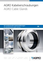
Kabelverschraubungen Cable Glands - siblik
Kabelverschraubungen Cable Glands - siblik
Kabelverschraubungen Cable Glands - siblik
Sie wollen auch ein ePaper? Erhöhen Sie die Reichweite Ihrer Titel.
YUMPU macht aus Druck-PDFs automatisch weboptimierte ePaper, die Google liebt.
Generelle Informationen Explosionsschutz<br />
Information about explosion protection<br />
<strong>Kabelverschraubungen</strong> Progress EX<br />
Montage-, Betriebs- und Wartungsanleitung<br />
Sicherheitshinweise<br />
<strong>Kabelverschraubungen</strong> Progress EX dürfen innerhalb explosionsgefährdeter Bereiche zur<br />
Einfüh rung von Kabeln und Leitungen in Schränke, Kästen oder sonstige Gehäuse, die in<br />
der Zündschutzart erhöhte Sicherheit „e“ ausge führt sind, ver wendet werden. Sie dürfen<br />
nur von qualifizierten Fachkräften mon tiert, in Betrieb genommen und gewartet<br />
werden.<br />
Verwenden Sie die Kabelverschraubung bestimmungsgemäß in unbeschädigtem und sauberem<br />
Zustand. Es dürfen keine Veränderungen an der Kabelverschraubung vorgenommen<br />
werden, die nicht ausdrück lich in dieser Betriebs anleitung aufge führt sind. Insbesondere das<br />
Erset zen des serienmäßigen Dichtein sat zes durch eine andere Größe ist nicht zulässig.<br />
Beachten Sie bei allen Arbeiten mit den <strong>Kabelverschraubungen</strong> Progress ® EX die<br />
nationalen Installations-, Sicherheits- und Unfallverhütungsvorschriften und die<br />
nachfol genden Sicher heitshinweise in dieser Betriebsanleitung, die wie dieser Text<br />
in Kursivschrift gefasst sind!<br />
Normenkonformität<br />
Die <strong>Kabelverschraubungen</strong> Progress EX entsprechen den Anforderungen der<br />
EN 60079-0:2004, EN 60079-1:2004, EN 61241-0:2006, EN 61241-1:2004 sowie der<br />
EN 1127-1:1997. Sie entsprechen dem Stand der Technik und sind gemäß ISO9001/<br />
EN 29001 entwickelt, gefertigt und geprüft.<br />
<strong>Cable</strong> glands Progress EX – Mounting, operating<br />
and maintenance instructions<br />
Safety information<br />
<strong>Cable</strong> glands Progress EX may be used inside areas where there is a risk of explosion for<br />
entry of cables and lines into cabinets, boxes or other housings which are in accordance to<br />
protection level increased safety «e». They may be mounted, put into operation and<br />
maintained only by qualified specialists.<br />
Use cable glands properly in the undamaged and clean state.The cable gland must not be<br />
modified in any way which is not expressly mentioned in these operation instructions. In<br />
particular, replacement of the standard sealing insert by different size is not permissible.<br />
During all work with cable glands Progress EX observe the national installation,<br />
safety and accident prevention regulations and the following safety information in<br />
these operating instructions, which appear in italics like this text!<br />
Conformity with standards<br />
The cable glands Progress EX meet the requirements of EN 50014:1997, of EN 50019:2000<br />
and of EN 1127-1:1997. They correspond to the state of the art and have been developed,<br />
manufactured and tested in accordance with EN 29001.<br />
Syntec ® | Syntec ®<br />
Progress ® | Progress ®<br />
Progress GFK EX Progress ... EX Progress .. HT .. EX<br />
Technische Daten<br />
Technical data<br />
Progress GFK EX Progress ... EX Progress .. HT .. EX<br />
Zulässige Umgebungs- und<br />
An wendungstemperatur Ta -20°C bis +85°C -40°C bis +100°C -40°C bis +200°C Permissible ambient and<br />
-20°C to +85°C -40°C to +100°C -40°C to +200°C<br />
application temperature Ta<br />
Werkstoff Gehäuse<br />
Messing vernickelt, Messing vernickelt,<br />
Polyamide PA6 Nickel plated brass Nickel plated brass<br />
Polyamid PA6 GF30 Housing material<br />
Stahl A2 oder A4 Stahl A2 oder A4<br />
GF30 Acier A2 or A4 Acier A2 or A4<br />
Werkstoff Dichteinsatz /<br />
Sealing insert material<br />
TPE / - TPE / NBR FPM / FPM<br />
O-Ring<br />
O-ring material<br />
TPE / - TPE / NBR FPM / FPM<br />
Farbe Dichteinsatz /<br />
Sealing insert colour<br />
schwarz / - schwarz / schwarz grün / grün<br />
O-Ring<br />
O-ring colour<br />
black / - black / black green / green<br />
Zündschutzart<br />
II G Ex e II II G Ex e II II G Ex e II<br />
II G Ex e II II G Ex e II II G Ex e II<br />
Explosion protection<br />
II D Ex tD A21 II D Ex tD A21 II D Ex tD A21<br />
II D Ex tD A21 II D Ex tD A21 II D Ex tD A21<br />
PTB 02 ATEX 1125 PTB 02 ATEX 1125<br />
PTB 02 ATEX 1125 PTB 02 ATEX 1125<br />
EG-Baumusterprüfbescheinigung<br />
1126 X<br />
certificate<br />
1126 X<br />
PTB 02 ATEX<br />
EC Type examination PTB 02 ATEX<br />
PTB 02 ATEX PTB 02 ATEX<br />
PTB 02 ATEX PTB 02 ATEX<br />
1126 X<br />
1126 X<br />
1126 X<br />
1126 X<br />
Installation<br />
Für das Errichten und Betreiben sind die Vorschriften gemäß EN60079-14, das<br />
Gerätesicher heitsgesetz, die allgemein anerkannten Regeln der Technik und diese<br />
Betriebsanleitung maß gebend. Damit der geforderte IP-Schutzgrad gemäß<br />
EN60529:1991 erreicht wird, müssen die Verschraubungen sachge recht im elektrischen<br />
Betriebsmittel eingebaut werden.<br />
Die Daten der <strong>Kabelverschraubungen</strong> unter Punkt 3 sind beim Einbau zu berücksichtigen.<br />
Beim Einsatz in Kunst stoffgehäuse müssen die <strong>Kabelverschraubungen</strong> in den Potentialausgleich<br />
einbezogen werden. Die auf der rückseitigen Tabelle für die jeweiligen Größen<br />
angege benen Anzugsdrehmomente für die Druck muttern und die Klemmbacken-Schrauben<br />
sowie die ergänzenden Hinweise sind zu beachten. Bei Typen mit einem nachstehenden X<br />
in der Prüfbescheinigungsnummer sind die besonderen Bedingungen der EG-Baumusterprüfbe<br />
scheini gung zu entnehmen.<br />
Instandhaltung<br />
Die für Wartung, Instandhaltung und Prüfung geltenden Bestimmungen der<br />
EN60‘079-14 sind einzuhalten. Im Rahmen der Wartung sind vor allem die für die<br />
Zündschutzart maßgebenden Teile zu prüfen.<br />
Anzugsdrehmomente<br />
Serienbezeichnung<br />
Series designation<br />
DM (Nm)<br />
M8 M10 M12<br />
Pg7<br />
KB (Ncm)<br />
DM (Nm)<br />
KB (Ncm)<br />
DM (Nm)<br />
KB (Ncm)<br />
DM (Nm)<br />
M16<br />
Pg9<br />
KB (Ncm)<br />
DM (Nm)<br />
Pg11<br />
KB (Ncm)<br />
M20<br />
Pg13/Pg16<br />
DM (Nm)<br />
KB (Ncm)<br />
M25<br />
Pg21<br />
DM (Nm)<br />
KB (Ncm)<br />
DM (Nm)<br />
M32 Pg29 M40 Pg36 M50<br />
Pg42<br />
Progress MS EX 2.5 2.5 3 6 6 8 11 15 15 20 28 30 40 44<br />
Progress MS EMV EX 2.5 2.5 3 6 6 8 11 15 15 20 28 30 40 44<br />
Progress GFK EX 3 3 4 9 10 12 16 20 24 34 36<br />
Progress MS KB EX 3 20 6 30 6 40 8 50 11 60 15 80 15 80 20 100 28 100 30 100 40 100 44 100<br />
Progress MS EMV KB EX 3 20 6 30 6 40 8 50 11 60 15 80 15 80 20 100 28 100 30 100 40 100 44 100<br />
Progress S2 KB EX 3 20 6 30 6 40 8 50 11 60 15 80 15 80 20 100 28 100 30 100 40 100 44 100<br />
Progress MS T+KB EX 6 30 6 40 8 50 11 60 15 80 15 80 20 100<br />
Progress MS HT KB EX 3 20 6 30 6 40 8 50 11 60 15 80 15 80 20 100 28 100 30 100 40 100 44 100<br />
Progress S2 HT KB EX 3 20 6 30 6 40 8 50 11 60 15 80 15 80 20 100 28 100 30 100 40 100 44 100<br />
Progress S4 HT KB EX 3 20 6 30 6 40 8 50 11 60 15 80 15 80 20 100 28 100 30 100 40 100 44 100<br />
Progress MS HT T+KB EX 6 30 6 40 8 50 11 60 15 80 15 80 20 100<br />
Obige Drehmomente für die Druckmuttern sind Maximalwerte bei größtem Kabel in<br />
normaler Umgebung. Um eine korrekte Montage bei davon abweichenden Bedingungen<br />
zu gewähr leisten, soll diese beendet werden, wenn der Dichteinsatz einen<br />
leicht über die Druckmutter vorstehenden Wulst bildet, selbst wenn das Drehmoment<br />
nach Tabelle noch nicht erreicht sein sollte.<br />
Legende DM = Druckmutter<br />
KB = Klemmbackenschraube<br />
Installation<br />
The regulations according to EN 60079-14, the equipment safety law, the generally<br />
acknowledged rules of the industry and these operating instructions are applicable<br />
for installation and operation. In order to ensure the required IP protection category<br />
according to EN 60529:1991 is achieved, the cable glands must be properly installed<br />
in the electrical operating equipment.<br />
The data for the cable gland under section 3 must be taken into account on installation.<br />
When used in enclosures made of plastic, the cable glands must be included in the equipotential<br />
bonding system. The tightening torques stated in the table for the respective sizes<br />
of compression cap nuts and clamps and the additional information must be taken into<br />
account. In case of types with an „X“ at the end in the test certificate number, the particular<br />
conditions are described in the EC type examination certificate.<br />
Maintenance<br />
The provisions of EN 60079-14 which are applicable for service, maintenance and<br />
testing must be complied with. During maintenance, in particular the parts critical<br />
for the ignition protection category must be tested.<br />
Mounting torques<br />
KB (Ncm)<br />
DM (Nm)<br />
KB (Ncm)<br />
DM (Nm)<br />
KB (Ncm)<br />
DM (Nm)<br />
KB (Ncm)<br />
DM (Nm)<br />
KB (Ncm)<br />
DM (Nm)<br />
Pg48<br />
KB (Ncm)<br />
DM (Nm)<br />
M63<br />
The above torques for the compression nuts are maximum values in the case of the<br />
largest cable in a normal environment. In order to ensure correct mounting under<br />
conditions differing from this, mounting should be terminated if the sealing insert<br />
forms a bead projecting slightly above the cap nut, even if the torque shown in the<br />
table has not yet been reached.<br />
Caption DM = Compression nut<br />
KB = Clamp<br />
115<br />
KB (Ncm)<br />
Service | Service Zubehör | Accessories Winkel | elbows.<br />
EX | EX<br />
EMV | EMC


