A3 A4 A6 A8 Servicemanual - Cab Produkttechnik GmbH & Co KG
A3 A4 A6 A8 Servicemanual - Cab Produkttechnik GmbH & Co KG
A3 A4 A6 A8 Servicemanual - Cab Produkttechnik GmbH & Co KG

Sie wollen auch ein ePaper? Erhöhen Sie die Reichweite Ihrer Titel.
YUMPU macht aus Druck-PDFs automatisch weboptimierte ePaper, die Google liebt.
Inhaltsverzeichnis<br />
1 Einführung............................................................... 5<br />
1.1 Hinweise für den Benutzer ....................................... 5<br />
1.2 Wichtige Informationen ............................................ 5<br />
1.3 Allgemeine Sicherheitshinweise ............................... 6<br />
1.4 Sicherheit beim Umgang mit Elektrizität .................. 7<br />
1.5 Leistungsmerkmale .................................................. 8<br />
1.6 Gerätetypen .............................................................. 9<br />
1.7 Lieferumfang ........................................................... 10<br />
1.8 Optionen ................................................................. 10<br />
1.9 Teile des Etikettendruckers .................................... 11<br />
1.10 Technische Daten................................................... 14<br />
2 Erweiterte Gerätefunktionen für den Service .... 19<br />
2.1 Der Serviceschlüssel .............................................. 19<br />
2.2 Erweiterte Funktionen im Menü "Einstellungen" .... 20<br />
2.2.1 Geräteeinstellungen ............................................... 20<br />
2.2.2 Druckparameter ...................................................... 21<br />
2.2.3 Schnittstellen .......................................................... 22<br />
2.3 Erweiterte Funktionen im Menü "Test" ................... 23<br />
2.3.1 Statusausdruck ....................................................... 24<br />
2.3.2 Geräteliste .............................................................. 26<br />
2.3.3 Ereignisliste ............................................................ 28<br />
2.3.4 IFFS Inhalt drucken ................................................ 29<br />
2.4 Erweiterte Funktionen im Menü "Service" .............. 30<br />
2.4.1 Servicezähler löschen ............................................ 30<br />
2.4.2 Etikettenlichtschranke abgleichen .......................... 32<br />
2.4.3 NVRAM sichern ...................................................... 33<br />
2.4.4 NVRAM laden ......................................................... 34<br />
3 Wartung ................................................................. 35<br />
3.1 Allgemeine Reinigung ............................................ 35<br />
3.2 Reinigung des Druckkopfes ................................... 35<br />
3.3 Reinigung der Druckwalze...................................... 36<br />
3.4 Reinigung der Etikettenlichtschranke ..................... 36<br />
3.4.1 Etikettenlichtschranke bei <strong>A3</strong> und <strong>A4</strong> ..................... 36<br />
3.4.2 Etikettenlichtschranke bei <strong>A6</strong> und <strong>A8</strong> ..................... 37<br />
4 Wechsel von Baugruppen ................................... 39<br />
4.1 Liste der benötigten Werkzeuge ............................ 39<br />
4.2 Demontage des Kunststoffdeckels ......................... 39<br />
4.3 Wechsel des Druckkopfes ...................................... 40<br />
4.3.1 Wechsel des Druckkopfes <strong>A3</strong>, <strong>A4</strong>, <strong>A8</strong> ................... 40<br />
4.3.2 Wechsel des Druckkopfes <strong>A6</strong> ................................ 42<br />
4.4 Wechsel von Druckwalze und Umlenkwalze .......... 44<br />
4.5 Wechsel der Rutschkupplungen ............................ 46<br />
4.6 Wechsel der Etikettenlichtschranke ....................... 49<br />
4.7 Wechsel der Leiterplatte CPU ................................ 51<br />
4.8 Wechsel des Netzteils <strong>A3</strong> ...................................... 54<br />
4.8.1 Drucker <strong>A3</strong> bis Seriennummer 14999 .................... 54<br />
4.8.2 Drucker <strong>A3</strong> ab Seriennummer 15000 ..................... 57<br />
4.9 Wechsel des Netzteils <strong>A4</strong>, <strong>A6</strong> ................................ 59<br />
4.9.1 Drucker <strong>A4</strong>/<strong>A6</strong> bis Seriennummer 14999 ............... 59<br />
4.9.2 Drucker <strong>A4</strong>/<strong>A6</strong> ab Seriennummer 15000 ............... 62<br />
4.10 Wechsel des Netzteils <strong>A8</strong> ...................................... 64<br />
<strong>Co</strong>ntent<br />
1 Introduction ............................................................. 5<br />
1.1 Scope of Information ................................................ 5<br />
1.2 Important Information ............................................... 5<br />
1.3 General Safety Instructions ...................................... 6<br />
1.4 Safe Handling of Electricity ...................................... 7<br />
1.5 Features ................................................................... 8<br />
1.6 Device Types ............................................................ 9<br />
1.7 Package <strong>Co</strong>ntents .................................................. 10<br />
1.8 Optional Features ................................................... 10<br />
1.9 Printer <strong>Co</strong>mponent Location ................................... 11<br />
1.10 Technical Specifications ......................................... 14<br />
2 Expanded Functions for Servicing ..................... 19<br />
2.1 The Service Key ..................................................... 19<br />
2.2 Expanded Functions in the "Setup" Menu .............. 20<br />
2.2.1 Machine Parameters .............................................. 20<br />
2.2.2 Print Parameters ..................................................... 21<br />
2.2.3 Interfaces ................................................................ 22<br />
2.3 Expanded Functions in the "Test" Menu ................ 23<br />
2.3.1 Status Print ............................................................. 24<br />
2.3.2 Device List .............................................................. 26<br />
2.3.3 Event Log ............................................................... 28<br />
2.3.4 Print Directory of IFFS ............................................ 29<br />
2.4 Expanded Functions in the "Service" Menu ........... 30<br />
2.4.1 Clearing the Service <strong>Co</strong>unters ............................... 30<br />
2.4.2 Adjusting the Label Edge Sensor ........................... 32<br />
2.4.3 Save NVRAM .......................................................... 33<br />
2.4.4 Load NVRAM .......................................................... 34<br />
3 Maintenance .......................................................... 35<br />
3.1 General Cleaning.................................................... 35<br />
3.2 Cleaning the Printhead ........................................... 35<br />
3.3 Cleaning the Print Roller ........................................ 36<br />
3.4 Cleaning the Label Edge Sensor............................ 36<br />
3.4.1 Label Edge Sensor of <strong>A3</strong> and <strong>A4</strong> ........................... 36<br />
3.4.2 Label Edge Sensor of <strong>A6</strong> and <strong>A8</strong> ........................... 37<br />
4 Replacing Assembly Units .................................. 39<br />
4.1 List of Recommended Tools ................................... 39<br />
4.2 Removing the Plastic <strong>Co</strong>ver ................................... 39<br />
4.3 Replacing the Printhead ......................................... 40<br />
4.3.1 Replacing the Printhead <strong>A3</strong>, <strong>A4</strong>, <strong>A8</strong> ....................... 40<br />
4.3.2 Replacing the Printhead <strong>A6</strong> .................................... 42<br />
4.4 Replacing the Print Roller and the Rewind Assist<br />
Roller ...................................................................... 44<br />
4.5 Replacing the Slipping Clutches ............................ 46<br />
4.6 Replacing the Label Edge Sensor .......................... 49<br />
4.7 Replacing the PCB CPU ......................................... 51<br />
4.8 Replacing the <strong>A3</strong> Power Supply ............................. 54<br />
4.8.1 <strong>A3</strong> Printers up to Serial Number 14999 .................. 54<br />
4.8.2 <strong>A3</strong> Printers with Serial Number 15000 or higher .... 57<br />
4.9 Replacing the <strong>A4</strong>/<strong>A6</strong> Power Supply ....................... 59<br />
4.9.1 <strong>A4</strong>/<strong>A6</strong> Printers up to Serial Number 14999 ............ 59<br />
4.9.2 <strong>A4</strong>/<strong>A6</strong> Printers with Serial Number 15000 or higher62<br />
4.10 Replacing the <strong>A8</strong> Power Supply ............................. 64<br />
Serviceanleitung / Service Manual / / /<br />
3
5 Justagen, Einstellungen und Abgleiche ............ 66<br />
5.1 Justage der Wickelmomente .................................. 66<br />
5.2 Justage der Druckmechanik ................................... 72<br />
5.2.1 Einstellelemente ..................................................... 72<br />
5.2.2 Justage ................................................................... 75<br />
5.3 Justage Riemenspannung Motor Hauptantrieb ...... 78<br />
5.4 Justage Kopfschalter .............................................. 79<br />
6 Fehlersuche und Fehlerbeseitigung ................... 80<br />
6.1 Fehler während des Druckbetriebs ........................ 80<br />
6.2 Ausfall von Gerätefunktionen ................................. 82<br />
6.3 Permanent angezeigte Hardwarefehler .................. 84<br />
Anlagen<br />
Anlage A - Ersatzteile ........................................................ A1<br />
Anlage B: Blockschaltbilder ......................................... B1-B5<br />
Anlage C: Stromlaufpläne .......................................... C1-C18<br />
Anlage D: Belegungspläne .......................................... D1-D5<br />
Stichwortverzeichnis ........................................................ I1<br />
5 Adjustments, Settings and Alignments .............. 66<br />
5.1 Adjusting the Hub Torques ..................................... 66<br />
5.2 Adjusting the Print Mechanism ............................... 72<br />
5.2.1 Adjusting Elements ................................................. 72<br />
5.2.2 Adjustment .............................................................. 75<br />
5.3 Adjusting the Belt Tension of the Main Motor Drive 78<br />
5.4 Adjusting the Head Switch...................................... 79<br />
6 Trouble Diagnosis and <strong>Co</strong>rrection ...................... 80<br />
6.1 Errors during Printing.............................................. 80<br />
6.2 Failure of Device Functions .................................... 82<br />
6.3 Permananently displayed Hardware Errors ............ 84<br />
Appendix<br />
Appendix A - Spare Parts .................................................. A1<br />
Appendix B: Block Diagrams ....................................... B1-B5<br />
Appendix C: Circuit Diagrams .................................... C1-C18<br />
Appendix D: Layout Diagrams ..................................... D1-D5<br />
Index ................................................................................. I1<br />
4 Serviceanleitung / Service Manual / / /
1 Einführung<br />
1.1 Hinweise für den Benutzer<br />
Dieses Handbuch ist für das qualifizierte Service- und<br />
Wartungspersonal vorgesehen.<br />
Es beinhaltet technische Informationen, die sich auf die<br />
Hardware und den mechanischen Teil der Etikettendrucker<br />
<strong>A3</strong>, <strong>A4</strong>, <strong>A6</strong> und <strong>A8</strong> beziehen.<br />
Informationen zur Bedienung des Druckers finden Sie in der<br />
Bedienungsanleitung.<br />
Informationen zur CABLABEL-Software finden Sie in der<br />
CABLABEL-Online-Hilfe.<br />
Tritt ein Problem auf, das mit Hilfe dieses Handbuches nicht<br />
behoben werden kann, wenden Sie sich an die Serviceabteilung<br />
von cab.<br />
cab-<strong>Produkttechnik</strong> <strong>GmbH</strong><br />
Wilhelm-Schickard-Straße 14<br />
D-76131 Karlsruhe<br />
Telefon 0721/6626-0<br />
Telefax 0721/6626-249<br />
1 Introduction<br />
1.1 Scope of Information<br />
This manual is intended for use by qualified service and<br />
maintenance personnel.<br />
The technical information included, relates to hardware and<br />
mechanical parts of the Label Printers <strong>A3</strong>, <strong>A4</strong>, <strong>A6</strong> and <strong>A8</strong>.<br />
Information related to the printer's operation will be found in<br />
the "Operator`s Manual" provided with the printer.<br />
Information related to the CABLABEL software will be found<br />
in the CABLABEL Online Help.<br />
If a problem occurs, which cannot be solved with the help of<br />
this manual, please contact the cab Technical Service<br />
Department.<br />
cab-<strong>Produkttechnik</strong> <strong>GmbH</strong><br />
Wilhelm-Schickard-Straße 14<br />
D-76131 Karlsruhe<br />
Telephone: +49 721 66 26-0<br />
Telefax: +49 721 66 26-249<br />
1.2 Wichtige Informationen<br />
Warnhinweise in diesem Servicehandbuch sind durch ein<br />
Pictogramm gekennzeichnet und enthalten wichtige Informationen<br />
zur Abwehr bestehender Restgefährdungen!<br />
Beispiel:<br />
Stromschlaggefahr!<br />
Im Gehäuse sind nach dem Öffnen<br />
spannungsführende berührbare Klemmen und<br />
Leitungen zugänglich! Vor Öffnen Netzstecker<br />
ziehen und Spannungsfreiheit prüfen!<br />
Nützliche Hinweise in diesem Servicehandbuch sind durch<br />
ein Pictogramm gekennzeichnet und enthalten allgemeine<br />
Informationen und Anwendertipps, die beachtet werden<br />
sollten!<br />
1.2 Important Information<br />
Warning notices in this manual are marked by a pictogram,<br />
and contain important information for guarding against any<br />
residual hazards.<br />
Example:<br />
Electric shock hazard!<br />
Opening the case exposes live electrical wires<br />
and terminals. Remove the mains plug and<br />
check that the device is electrically dead<br />
before opening the case.<br />
Useful information in this service manual is marked with a<br />
pictogram, and contains general information and user tips<br />
which should be followed.<br />
Beispiel:<br />
Hinweis!<br />
Die beiden Kühlwinkelschrauben sind kürzer<br />
(6 mm lang)!<br />
Example:<br />
Notice!<br />
The two cooling angle screws are shorter (6<br />
mm long).<br />
Serviceanleitung / Service Manual / / /<br />
5
1.3 Allgemeine Sicherheitshinweise<br />
Beachten Sie die folgenden Regeln zur allgemeinen<br />
Sicherheit:<br />
Ÿ Halten Sie die Umgebung des Gerätes während und<br />
nach der Wartung sauber!<br />
Ÿ Führen Sie keine Tätigkeiten aus, die Personen in<br />
Gefahr bringen oder das Gerät zu einer Gefahrenquelle<br />
machen können!<br />
Ÿ Bewahren Sie entfernte Gehäuse- und andere Geräteteile<br />
während der Wartungsarbeiten sicher auf!<br />
Ÿ Stellen Sie den Werkzeugkoffer immer so hin, dass<br />
niemand darüber stolpern oder stürzen kann!<br />
Ÿ Ihre Kleidung muss so beschaffen sein, dass sie sich<br />
nicht in laufenden Geräteteilen verfangen kann.<br />
Knöpfen Sie Hemds- oder Jackenärmel zu oder rollen<br />
diese hoch. Binden Sie lange Haare zusammen oder<br />
stecken Sie diese hoch. Stecken Sie Enden von<br />
Halstüchern, Krawatten oder Schals in die Kleidung<br />
oder befestigen Sie diese mit einer nichtleitenden<br />
Klammer.<br />
Ÿ Tragen Sie keinen Schmuck, keine Brillen mit Metallrändern<br />
oder Kleidung mit Metallverschlüssen!<br />
Ÿ<br />
Ÿ<br />
Hinweis!<br />
Wenn solche Metallteile mit dem<br />
Gerät in Kontakt kommen, führt<br />
dies aufgrund der guten Leitfähigkeit von<br />
Metallen zu einem verstärkten Stromfluss.<br />
Tragen Sie bei folgenden Tätigkeiten eine Schutzbrille:<br />
- beim Ein- oder Ausschlagen von Stiften oder ähnlichen<br />
Teilen mit einem Hammer<br />
- beim Arbeiten mit einer elektrischen Bohrmaschine<br />
- beim Verwenden von Federhaken<br />
- beim Lösen oder Einsetzen von Federn, Sicherungsringen<br />
und Greifringen<br />
- bei Lötarbeiten<br />
- bei der Verwendung von Lösungsmitteln, Reinigern<br />
oder sonstigen Chemikalien<br />
- generell bei einer möglichen Gefährdung der Augen<br />
aufgrund der Arbeitsbedingungen.<br />
Bringen Sie nach Ausführung der Wartungsarbeiten<br />
sämtliche Schutzvorrichtungen wie Abdeckungen,<br />
Sicherheitshinweise und Erdungskabel wieder an!<br />
Tauschen Sie fehlerhafte oder unbrauchbar gewordene<br />
Teile aus!<br />
1.3 General Safety Instructions<br />
Follow the general safety rules below:<br />
Ÿ<br />
Ÿ<br />
Ÿ<br />
Ÿ<br />
Ÿ<br />
Ÿ<br />
Ÿ<br />
Ÿ<br />
Keep the area around the device clean at all times!<br />
Avoid performing maintenance which might expose<br />
persons to danger or make the device a source of<br />
danger!<br />
Save housing or other parts of the device removed<br />
during maintenance!<br />
Keep tools out of the way to avoid injury to yourself or<br />
others not involved in the maintenance!<br />
Do not wear loose clothing that could be caught in<br />
moving parts of the device. Button up your shirt or<br />
jacket sleeves or roll them up. Tie back or put up long<br />
hair. Tuck the ends of scarves, ties and shawls into<br />
your clothing and attach them with a non-conducting<br />
clip.<br />
Do not wear jewelry, glasses with a metal frame or<br />
clothing with metal fasteners!<br />
Notice!<br />
If such metal parts contact the device, they<br />
cause an increased current flow due to good<br />
conductivity!<br />
Wear protective goggles while performing the following<br />
tasks:<br />
- while driving pins or similar parts in or out with a<br />
hammer<br />
- while working at an electric drilling machine<br />
- while using spring hooks or springs<br />
- while inserting or removing springs, locking rings or<br />
grab rings<br />
- while soldering<br />
- while using solvents, cleansers or other chemical<br />
substances<br />
- in any case where the working conditions are such<br />
that there could be a risk of injury to the eyes.<br />
Refit all protective devices such as covers, safety instructions,<br />
and grounding cable upon completion of the<br />
maintenance work! Replace all faulty or defective parts!<br />
6 Serviceanleitung / Service Manual / / /
1.4 Sicherheit beim Umgang mit<br />
Elektrizität<br />
Beachten Sie beim Umgang mit Elektrizität folgende<br />
zusätzliche Regeln:<br />
Ÿ Reparatur-, Prüf- und sonstige Arbeiten an elektrischen<br />
Baugruppen dürfen nur durch eingewiesene und<br />
geschulte Elektrofachkräfte durchgeführt werden!<br />
Eine Elektrofachkraft nach DIN EN 50110-1 hat:<br />
- Kenntnisse der Elektrotechnik und der Gefährdungen,<br />
die während der Arbeit am geöffneten Gerät<br />
entstehen können.<br />
- Kenntnisse über die zu beachtenden Sicherheitsund<br />
Sicherungsmaßnahmen.<br />
- Erfahrung mit elektrotechnischen Arbeiten.<br />
- Kenntnisse des Gerätes sowie praktische Erfahrungen.<br />
Ÿ Arbeiten am geöffneten Gerät, das an das Stromnetz<br />
angeschlossen ist, darf nur eine geschulte und unterwiesene<br />
Fachkraft ausführen!<br />
Ÿ Stellen Sie die Lage vom Not- oder Netzschalter fest,<br />
um ihn im Notfall schneller bedienen zu können!<br />
Ÿ Arbeiten Sie bei gefährlichen Arbeitsbedingungen oder<br />
bei Arbeiten an Geräten mit offenliegenden Spannungen<br />
(über 50 V Wechselspannung oder 120 V Gleichspannung)<br />
nicht allein!<br />
Ÿ Bei folgenden Arbeiten müssen Sie vorher die Stromzufuhr<br />
unterbrechen:<br />
- Entfernen oder Installieren von Netzteilen<br />
- Arbeiten in unmittelbarer Nähe von offenen<br />
Stromversorgungsteilen<br />
- mechanische Überprüfung von Stromversorgungsteilen<br />
- Änderungen an Geräteschaltkreisen.<br />
Ÿ Wenn es sich nicht vermeiden lässt, dass Sie an<br />
Geräten mit offenliegenden Spannungen arbeiten,<br />
treffen Sie folgende Sicherheitsvorkehrungen:<br />
- Eine Person, die mit der Lage und Bedienung der<br />
Netzschalter vertraut ist und bei Gefahr den Strom<br />
abschaltet, muss sich in unmittelbarer Nähe bereithalten.<br />
- Verwenden Sie nur Werkzeuge und Testgeräte, die<br />
für die entsprechende Tätigkeit geeignet sind.<br />
- Verwenden Sie nur eine Hand, wenn Sie an elektrischen<br />
Kreisen eingeschalteter Geräte arbeiten.<br />
Halten Sie die andere Hand solange hinter dem<br />
Rücken oder stecken Sie diese in die Tasche.<br />
1.4 Safe Handling of Electricity<br />
Follow the additional instructions below when handling<br />
electricity:<br />
Ÿ Repair, testing and other work on electrical<br />
components may only be carried out by qualified and<br />
trained electricians. According to DIN EN 50110-1, an<br />
electrician has:<br />
- Knowledge of electrical engineering and the hazards<br />
which could arise while working on an open device.<br />
- Knowledge of the safety and precautionary measures<br />
which have to be taken.<br />
- Experience of electrical engineering work.<br />
- Knowledge of the device and practical experience.<br />
Ÿ<br />
Ÿ<br />
Ÿ<br />
Ÿ<br />
Ÿ<br />
Work on an open device which is connected to the<br />
mains supply may only be performed by a qualified and<br />
trained electrician.<br />
Find out the positions of the emergency and the power<br />
switches in order to be able to operate them quickly in<br />
an emergency situation!<br />
Do not work alone under dangerous working conditions<br />
or while working on devices with non-protected<br />
voltages (over 50 V AC or 120 V DC)!<br />
Turn off the power to the printer before:<br />
- removing or installing power units<br />
- working near open power supply parts<br />
- mechanical check of the power supply parts<br />
- changing circuit boards or electrical parts<br />
If you cannot avoid working on devices with nonprotected<br />
voltages, follow these safety precautions:<br />
- Have a person nearby who is aware of the position<br />
and operation of the power switches, who will switch<br />
off the power in case of danger.<br />
- Use only tools and test devices, which are suitable<br />
for the work being done.<br />
- Work only with one hand on devices that are<br />
switched on. Keep the other hand behind your back<br />
or in your pocket until you have finished.<br />
Notice!<br />
A shock occurs only with a closed circuit. By<br />
using only one hand, as described above, you<br />
will avoid a current flowing through your own<br />
body.<br />
Hinweis!<br />
Ein Stromschlag setzt einen geschlossenen<br />
Stromkreis voraus. Auf die oben beschriebene<br />
Weise wird verhindert, dass ein Stromfluss<br />
über den eigenen Körper zustande kommt.<br />
Ÿ<br />
Ÿ<br />
Do not use worn or defective tools!<br />
Never assume that a circuit is not powered. You must<br />
always verify that there is no voltage present!<br />
Ÿ<br />
Ÿ<br />
Verwenden Sie keine abgenutzten oder schadhaften<br />
Werkzeuge!<br />
Nehmen Sie nie an, dass ein Stromkreis unterbrochen<br />
ist! Sie müssen immer die Spannungsfreiheit feststellen!<br />
Serviceanleitung / Service Manual / / /<br />
7
Ÿ<br />
Ÿ<br />
Untersuchen Sie immer den Arbeitsbereich auf mögliche<br />
Gefahrenquellen, wie z.B. feuchte Fußböden,<br />
defekte Verlängerungskabel, fehlerhafte Schutzleiterverbindungen<br />
usw.<br />
Bei Unfällen mit Elektrizität:<br />
- Gehen Sie vorsichtig vor und vermeiden Sie die<br />
Gefährdung der eigenen Person.<br />
- Schalten Sie den Strom ab.<br />
- Fordern Sie ärztliche Hilfe (Notarzt) an.<br />
- Leisten Sie gegebenenfalls Erste Hilfe.<br />
Ÿ<br />
Ÿ<br />
Always examine the work area for possible sources of<br />
danger, such as wet floors, defective extension cords,<br />
faulty protective grounding connectors etc.<br />
If you observe an accident with electricity:<br />
- Be careful and avoid danger to yourself.<br />
- Switch off power.<br />
- Request medical assistance.<br />
- Give first aid, if necessary.<br />
1.5 Leistungsmerkmale<br />
Die Etikettendrucker <strong>A3</strong>, <strong>A4</strong>, <strong>A6</strong> und <strong>A8</strong> sind<br />
Thermodirekt-/ Thermotransferdrucker<br />
mit folgenden Eigenschaften:<br />
Ÿ langlebig, für den dauerhaften Industrieeinsatz<br />
konzipiert u. zum Einbau in Etikettieranlagen geeignet<br />
Ÿ verschleißfeste Lager und Transportrollen für gleichbleibende<br />
Druckqualität und lange Lebensdauer<br />
Ÿ einfache und komfortable Bedienung<br />
Ÿ Statusinformation über LCD-Anzeige<br />
Ÿ anschließbare Standard-Tastatur und Barcodeleser<br />
Ÿ Schnittstelle für <strong>Co</strong>mpactFlash Card<br />
Ÿ menügeführte Programmierung<br />
Ÿ Druckkopfwechsel ohne Justage<br />
(bei <strong>A3</strong> auch zwischen 203 dpi u. 300 dpi)<br />
Ÿ Weitbereichsnetzteil von 100 bis 240 V~, keine<br />
Spannungsumschaltung notwendig<br />
Ÿ 32 Bit Prozessor<br />
Ÿ <strong>A3</strong> mit 8 MB Arbeitsspeicher (RAM)<br />
Ÿ <strong>A4</strong>, <strong>A6</strong> und <strong>A8</strong> mit 16 MB Arbeitsspeicher (RAM)<br />
Ÿ umfangreiche Schriften, Zeichensätze und Grafikelemente<br />
nutzbar<br />
Ÿ freie Wahl der Schriften in Höhe und Breite, invers,<br />
kursiv und beliebig gedreht durch Vektor-Schriftarten<br />
Ÿ Datenübertragung durch die Schnittstellen:<br />
parallel, Centronics bidirektional, seriell, RS-232<br />
Ÿ druckerinterne Website zur Druckerkonfiguration bei<br />
Betrieb mit der optionalen Ethernetkarte<br />
Ÿ modularer Aufbau für schnellen und effizienten<br />
Service.<br />
1.5 Features<br />
The <strong>A3</strong>, <strong>A4</strong>, <strong>A6</strong> and <strong>A8</strong> Label Printers are<br />
direct thermal and thermal transfer printers<br />
offering the following features:<br />
Ÿ long lifetime, intended for permanent industrial use and<br />
suited for installation in labelling systems<br />
Ÿ long wearing bearings and conveyor rollers for<br />
maximum print quality and a long lifetime<br />
Ÿ easy and comfortable operation<br />
Ÿ status information on LCD<br />
Ÿ standard keyboards and barcode readers pluggable<br />
Ÿ <strong>Co</strong>mpactFlash Card interface<br />
Ÿ menu controlled programming<br />
Ÿ printhead change without adjustment<br />
(for <strong>A3</strong> between 203 dpi and 300 dpi, too)<br />
Ÿ wide-range power unit from 100 to 240 V~, no voltage<br />
changeover required<br />
Ÿ 32 bit processor<br />
Ÿ <strong>A3</strong> with 8 MB input memory (RAM)<br />
Ÿ <strong>A4</strong>, <strong>A6</strong> and <strong>A8</strong> with 16 MB input memory (RAM)<br />
Ÿ wide range of fonts, character sets and graphic<br />
elements available<br />
Ÿ scaleable fonts allow for variety regarding their height<br />
and width, with inverse, italic, underline and bold<br />
effects, and arbitrary rotation of fields<br />
Ÿ data transmission through the interfaces:<br />
parallel, Centronics bidirectional, RS-232<br />
Ÿ internal webpage for printer configuration for operation<br />
with the optional Ethernet card<br />
Ÿ modular structure for quick and efficient service.<br />
8 Serviceanleitung / Service Manual / / /
1.6 Gerätetypen<br />
<strong>A3</strong> ist sowohl als Thermotransferdrucker und<br />
Thermodirektdrucker verfügbar und wird in folgenden<br />
Gerätetypen hergestellt:<br />
Ÿ <strong>A3</strong>/200 mit 203dpi-Dickschicht-Druckkopf<br />
Ÿ <strong>A3</strong>/200R mit 203dpi-Dickschicht-Druckkopf,<br />
mit internem Aufwickler<br />
Ÿ <strong>A3</strong>/200P mit 203dpi-Dickschicht-Druckkopf,<br />
mit internem Aufwickler und zusätzlichem Transportsystem<br />
für Spendebetrieb<br />
1.6 Device Types<br />
<strong>A3</strong> is produced in following types and is available both as<br />
thermal transfer printer and as direct thermal printer:<br />
Ÿ <strong>A3</strong>/200 with 203dpi printhead<br />
Ÿ <strong>A3</strong>/200R with 203dpi printhead,<br />
with internal rewinder<br />
Ÿ <strong>A3</strong>/200P with 203dpi printhead,<br />
with internal rewinder and additional transport system<br />
for peel-off mode<br />
Ÿ<br />
Ÿ<br />
Ÿ<br />
<strong>A3</strong>/300 mit 300dpi-Dickschicht-Druckkopf<br />
<strong>A3</strong>/300R mit 300dpi-Dickschicht-Druckkopf,<br />
mit internem Aufwickler<br />
<strong>A3</strong>/300P mit 300dpi-Dickschicht-Druckkopf,<br />
mit internem Aufwickler und zusätzlichem Transportsystem<br />
für Spendebetrieb<br />
Ÿ<br />
Ÿ<br />
Ÿ<br />
<strong>A3</strong>/300 with 300dpi printhead<br />
<strong>A3</strong>/300R with 300dpi printhead,<br />
with internal rewinder<br />
<strong>A3</strong>/300P with 300dpi printhead,<br />
with internal rewinder and additional transport system<br />
<strong>A4</strong> wird in folgenden Gerätetypen als<br />
Thermotransferdrucker hergestellt:<br />
Ÿ <strong>A4</strong>/300 mit 300dpi-Dünnschicht-Druckkopf<br />
Ÿ <strong>A4</strong>/300R mit 300dpi-Dünnschicht-Druckkopf,<br />
mit internem Aufwickler<br />
Ÿ <strong>A4</strong>/300P mit 300dpi-Dünnschicht-Druckkopf,<br />
mit internem Aufwickler und zusätzlichem Transportsystem<br />
für Spendebetrieb<br />
<strong>A4</strong> is produced in following types as<br />
thermal transfer printer:<br />
Ÿ <strong>A4</strong>/300 with 300dpi printhead<br />
Ÿ <strong>A4</strong>/300R with 300dpi printhead,<br />
with internal rewinder<br />
Ÿ <strong>A4</strong>/300P with 300dpi printhead,<br />
with internal rewinder and additional transport system<br />
for peel-off mode<br />
Ÿ<br />
Ÿ<br />
Ÿ<br />
<strong>A4</strong>/600 mit 600dpi-Dünnschicht-Druckkopf<br />
<strong>A4</strong>/600R mit 600dpi-Dünnschicht-Druckkopf,<br />
mit internem Aufwickler<br />
<strong>A4</strong>/600P mit 600dpi-Dünnschicht-Druckkopf,<br />
mit internem Aufwickler und zusätzlichem Transportsystem<br />
für Spendebetrieb<br />
Ÿ<br />
Ÿ<br />
Ÿ<br />
<strong>A4</strong>/600 with 600dpi printhead<br />
<strong>A4</strong>/600R with 600dpi printhead,<br />
with internal rewinder<br />
<strong>A4</strong>/600P with 600dpi printhead,<br />
with internal rewinder and additional transport system<br />
<strong>A6</strong> ist sowohl als Thermotransferdrucker und<br />
Thermodirektdrucker verfügbar und wird in folgenden<br />
Gerätetypen hergestellt:<br />
Ÿ <strong>A6</strong>/300 mit 300dpi-Dickschicht-Druckkopf<br />
Ÿ <strong>A6</strong>/300P mit 300dpi-Dickschicht-Druckkopf,<br />
mit internem Aufwickler und zusätzlichem Transportsystem<br />
für Spendebetrieb<br />
<strong>A6</strong> is produced in following types and is available both as<br />
thermal transfer printer and as direct thermal printer:<br />
Ÿ <strong>A6</strong>/300 with 300dpi printhead<br />
Ÿ <strong>A6</strong>/300P with 300dpi printhead,<br />
with internal rewinder and additional transport system<br />
<strong>A8</strong> ist sowohl als Thermotransferdrucker und<br />
Thermodirektdrucker verfügbar und wird in folgenden<br />
Gerätetypen hergestellt:<br />
Ÿ <strong>A8</strong>/300 mit 300dpi-Dickschicht-Druckkopf<br />
<strong>A8</strong> is produced in following types and is available both as<br />
thermal transfer printer and as direct thermal printer:<br />
Ÿ <strong>A8</strong>/300 with 300dpi printhead<br />
Serviceanleitung / Service Manual / / /<br />
9
1.7 Lieferumfang<br />
Mit Ihrem Etikettendrucker sind im Standard-Lieferumfang<br />
enthalten:<br />
Ÿ leerer Folienkern (nur Transferdrucker)<br />
Ÿ Abreißblech (nur bei Basisversion)<br />
Ÿ Umlenkblech (nur bei R-Version)<br />
Ÿ Spendekante (nur bei P-Version)<br />
Ÿ Netzkabel für Deutschland<br />
Ÿ CD mit Etikettensoftware CABLABEL LITE<br />
Ÿ CD mit Dokumentationen und Windows-Treiber.<br />
Wenn Sie Ihren Etikettendrucker an einen anderen Ort<br />
transportieren möchten, verwenden Sie nach Möglichkeit<br />
immer die Originaltransportverpackung.<br />
Bei Verwendung einer anderen Verpackung muss das Gerät<br />
auf jeder Seite durch mindestens 5 cm Dämmmaterial<br />
gegen Stoß geschützt werden.<br />
Sachschäden!<br />
Nicht zweckentsprechende Verpackung kann<br />
zur Beschädigung des Druckers führen.<br />
Schützen Sie das Gerät ausreichend vor Stoß!<br />
1.7 Package <strong>Co</strong>ntents<br />
As delivered, the Label Printer standard package includes<br />
besides the printer:<br />
Ÿ Empty Cardboard <strong>Co</strong>re (Transfer printer only)<br />
Ÿ Tear-off Plate (Basic version only)<br />
Ÿ Rewind Guide Plate (R-version only)<br />
Ÿ Dispense Plate (P-versions only)<br />
Ÿ Power <strong>Co</strong>rd for Germany<br />
Ÿ CD with Label Software CABLABEL LITE<br />
Ÿ CD with documentations and Windows printer driver.<br />
In case the label printer may be transported to another<br />
location in future, always retain and use the original<br />
packing.<br />
If you use other packing material, the device must be<br />
protected against shock by applying at least 2" (5 cm) of<br />
packaging material on each side.<br />
Material damage!<br />
Incorrect packing may cause damage to the<br />
printer. Protect the device adequately against<br />
impacts.<br />
1.8 Optionen<br />
Zur Erweiterung der Einsatzmöglichkeiten der Etikettendrucker<br />
<strong>A3</strong>, <strong>A4</strong>, <strong>A6</strong> und <strong>A8</strong> stehen die folgenden Optionen<br />
zur Verfügung:<br />
Ÿ Externer Aufwickler, Externer Abwickler<br />
Ÿ Schneidemesser<br />
Ÿ Spendelichtschranke, Spendeadapter, Pauseadapter<br />
Ÿ Externe Bedienelemente:<br />
Tastatur, Scanner, Externes Bedienfeld<br />
Ÿ Schnittstellen:<br />
RS422/485 oder Ethernet oder USB Slave für PC<br />
Anschluss<br />
Ÿ Twinax/<strong>Co</strong>ax-<strong>Co</strong>nverter für IBM-Anschluss<br />
Ÿ Speicherkarten, <strong>Co</strong>mpactFlash Card T1, bis 512 MB<br />
Ÿ Etikettensoftware CABLABEL<br />
Ÿ Metalldeckel (Standard beim <strong>A8</strong>)<br />
Ÿ Stativ A 1600<br />
1.8 Optional Features<br />
The features listed below are optionally available for the<br />
Label Printers <strong>A3</strong>, <strong>A4</strong>, <strong>A6</strong> and <strong>A8</strong>:<br />
Ÿ External Rewinder, External Unwinder<br />
Ÿ Cutter<br />
Ÿ Present Sensor, Peel-off Adapter, Pause Adapter<br />
Ÿ External devices:<br />
keyboard, scanner, External <strong>Co</strong>ntrol Panel<br />
Ÿ Interfaces:<br />
RS422/485 or Ethernet or USB slave for PC connection<br />
Ÿ Twinax/<strong>Co</strong>ax converter for IBM connection<br />
Ÿ Memory modules, <strong>Co</strong>mpactFlash Card T1, to 512 MB<br />
Ÿ CABLABEL software<br />
Ÿ Applicator A 1000 for <strong>A3</strong> and <strong>A4</strong> for stamping, blowing<br />
or roll on labels onto the product<br />
Ÿ Metal <strong>Co</strong>ver (standard with the <strong>A8</strong>)<br />
Ÿ Stand A 1600<br />
10 Serviceanleitung / Service Manual / / /
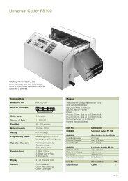
1.9 Teile des Etikettendruckers 1.9 Printer <strong>Co</strong>mponent Location<br />
11<br />
12<br />
1<br />
2<br />
10<br />
9<br />
8<br />
13<br />
14<br />
3<br />
15<br />
4 5 6 7<br />
Bild 1<br />
Gesamtansicht<br />
1 - Vorwarnetikett Transferfolienende<br />
2 - Bedienfeld<br />
3 - Spendemodul (optional bei A-Serie P-Version)<br />
4 - Druckmechanik<br />
5 - Interner Aufwickler (nicht in A-Serie Basisversion)<br />
6 - Transferfolienaufwickler<br />
7 - Transferfolienabwickler<br />
8 - Rollenhalter<br />
9 - Führung<br />
10 - Vorwarnetikett Papierende<br />
11 - Deckel<br />
Abweichungen beim <strong>A8</strong>:<br />
12 - Metallhaube<br />
13 - 2 Wickeladapter<br />
14 - Etikettenabwickler<br />
15 - Stütze<br />
Fig. 1<br />
General View<br />
1 - Warning label ''End of Ribbon''<br />
2 - <strong>Co</strong>ntrol Panel<br />
3 - Peel-off module (Option for A-Series P-version)<br />
4 - Print mechanism<br />
5 - Internal Rewinder (not at A-Series Basic version)<br />
6 - Ribbon take up hub<br />
7 - Ribbon supply hub<br />
8 - Media hub<br />
9 - Media Retainer<br />
10 - Warning label ''End of Paper''<br />
11 - <strong>Co</strong>ver<br />
Deviations at <strong>A8</strong>:<br />
12 - Metal <strong>Co</strong>ver<br />
13 - 2 Adapters<br />
14 - Media Unwinder<br />
15 - Plate<br />
Serviceanleitung / Service Manual / / /<br />
11
1<br />
2<br />
16<br />
3<br />
15<br />
4<br />
5<br />
14<br />
6<br />
13<br />
7<br />
12<br />
8<br />
11<br />
9<br />
10<br />
Bild 2<br />
Druckmechanik<br />
1 - Schraube zur Druckkopfbefestigung<br />
2 - Transferfolienumlenkblech<br />
3 - Etikettenlichtschranke<br />
4 - Druckwalze<br />
5 - Spendekante (nur bei A-Serie P-Version)<br />
6 - Umlenkwalze (nur bei A-Serie P-Version)<br />
7 - Andrucksystem (nur bei A-Serie P-Version)<br />
8 - Druckkopfabstützung<br />
9 - Feststellschraube zur Einstellung des Andrucksystems<br />
(nur bei A-Serie P-Version)<br />
10 - Feststellschraube zur Einstellung der Druckkopfabstützung<br />
11 - Sechskantschlüssel<br />
12 - Führungsring<br />
13 - Umlenkachse (<strong>A3</strong>)<br />
Schwinge (<strong>A4</strong>, <strong>A6</strong> und <strong>A8</strong>)<br />
14 - Thermodruckkopf<br />
15 - Schraube zur Justage des Transferfolienumlenkblechs<br />
16 - Hebel zur Druckkopfverriegelung<br />
Fig. 2<br />
Print Mechanism<br />
1 - Printhead locking screw<br />
2 - Ribbon shield<br />
3 - Label edge sensor<br />
4 - Media feed roller<br />
5 - Dispense plate (for A-Series P-version only)<br />
6 - Rewind assist roller (for A-Series P-version only)<br />
7 - Locking system (for A-Series P-version only)<br />
8 - Printhead support<br />
9 - Screw for adjusting locking system (for A-Series P-<br />
version only)<br />
10 - Screw for adjusting printhead support<br />
11 - Allen key<br />
12 - Media guide<br />
13 - Guide axle (<strong>A3</strong>)<br />
Swing (<strong>A4</strong>, <strong>A6</strong> and <strong>A8</strong>)<br />
14 - Thermal printhead<br />
15 - Screw to adjust the ribbon shield<br />
16 - Printhead lever<br />
12 Serviceanleitung / Service Manual / / /
1<br />
2<br />
Bild 3<br />
Abreiß- und Umlenkblech<br />
1 - Abreißblech (nur A-Serie Basisversion)<br />
2 - Umlenkblech (nur A-Serie R-Version)<br />
Fig. 3<br />
Tear-off Plate and Rewind Guide Plate<br />
1 - Tear-off plate (A-Series Basic version only)<br />
2 - Rewind Guide Plate (A-Series R-version only)<br />
1<br />
2<br />
3<br />
4<br />
5<br />
6<br />
Bild 4<br />
Rückansicht<br />
1 - Einschub für zusätzliche Schnittstellen-Karte<br />
(RS-422/485, Ethernet oder USB Slave)<br />
2 - bidirektionale Parallelschnittstelle<br />
3 - USB-Master-Schnittstelle für Tastatur oder Scanner<br />
4 - RS-232-Schnittstelle<br />
5 - Netzschalter<br />
6 - Netzanschlussbuchse<br />
Fig. 4<br />
Back View<br />
1 - Slot for additional interface card<br />
(RS-422/485, Ethernet or USB Slave)<br />
2 - Bi-directional parallel interface<br />
3 - USB master interface for keyboard or scanner<br />
4 - RS-232 interface<br />
5 - Power switch<br />
6 - Power supply connector<br />
Serviceanleitung / Service Manual / / /<br />
13
1.10 Technical Specifications<br />
1.10 Technische Daten<br />
Flächengewicht: 60 bis 250 g/m 2 Weight: 60 to 250 g/m 2<br />
Druckkopf<br />
Printhead<br />
Druckprinzip: Thermo-/Thermotransferdruck<br />
Type:<br />
Thermal-/Thermal transfer printer<br />
Druckkopf: <strong>A3</strong>, <strong>A6</strong>, <strong>A8</strong>: Dickschicht-Transferkopf Printhead: <strong>A3</strong>, <strong>A6</strong>, <strong>A8</strong>: Thick film transfer head<br />
<strong>A4</strong>: Dünnschicht-Transferkopf<br />
<strong>A4</strong>: Thin film transfer head<br />
Druckkopf- <strong>A3</strong>/200: 203 dpi=8 Punkte/mm Printhead <strong>A3</strong>/200: 203 dpi=8 dots/mm<br />
auflösung: <strong>A3</strong>/300: 300 dpi=11,8 Punkte/mm resolution: <strong>A3</strong>/300: 300 dpi=11.8 dots/mm<br />
<strong>A4</strong>/300: 300 dpi=11,8 Punkte/mm<br />
<strong>A4</strong>/300: 300 dpi=11,8 dots/mm<br />
<strong>A4</strong>/600: 600 dpi=23,6 Punkte/mm<br />
<strong>A4</strong>/600: 600 dpi=23,6 dots/mm<br />
<strong>A6</strong>/300: 300 dpi=11,8 Punkte/mm<br />
<strong>A6</strong>/300: 300 dpi=11,8 dots/mm<br />
<strong>A8</strong>/300: 300 dpi=11,8 Punkte/mm<br />
<strong>A8</strong>/300: 300 dpi=11,8 dots/mm<br />
Anzahl der <strong>A3</strong>/200: 832<br />
Dots/Line: <strong>A3</strong>/200: 832<br />
Punkte/Zeile: <strong>A3</strong>/300 : 1280<br />
<strong>A3</strong>/300: 1280<br />
<strong>A4</strong>/300: 1248<br />
<strong>A4</strong>/300: 1248<br />
<strong>A4</strong>/600: 2496<br />
<strong>A4</strong>/600: 2496<br />
<strong>A6</strong>/300: 1920<br />
<strong>A6</strong>/300: 1920<br />
<strong>A8</strong>/300: 2560<br />
<strong>A8</strong>/300: 2560<br />
Druckbreite: <strong>A3</strong>/200: bis 104,0 mm<br />
Printing width: <strong>A3</strong>/200: to 4.09" (104 mm)<br />
<strong>A3</strong>/300: bis 108,4 mm<br />
<strong>A3</strong>/300: to 4.26" (108.4 mm)<br />
<strong>A4</strong>/300: bis 105,6 mm<br />
<strong>A4</strong>/300: to 4.15" (105.6 mm)<br />
<strong>A4</strong>/600: bis 105,6 mm<br />
<strong>A4</strong>/600: to 4.15" (105.6 mm)<br />
<strong>A6</strong>/300: bis 162,6 mm<br />
<strong>A6</strong>/300: to 4.40" (162.6 mm)<br />
<strong>A8</strong>/300: bis 216,0 mm<br />
<strong>A8</strong>/300: to 8.50" (216.0 mm)<br />
Druckgeschwindig- <strong>A3</strong>/200: 50, 75, 100, 125, 150, Printing speed: <strong>A3</strong>/200: 2, 3, 4, 5, 6, 7, 8 ips<br />
keit:<br />
175, 200 mm/s<br />
(50, 75, 100, 125, 150,<br />
<strong>A3</strong>/300: 50, 75, 100,125,<br />
175, 200 mm/s)<br />
150 mm/s<br />
<strong>A3</strong>/300: 2, 3, 4, 5, 6 ips<br />
<strong>A4</strong>/300: 50, 75, 100,125, 150,<br />
175, 200, 225, 250 mm/s<br />
(50, 75, 100, 125,<br />
150 mm/s)<br />
<strong>A4</strong>/600: 50, 75,<br />
100 mm/s<br />
<strong>A4</strong>/300: 2, 3, 4, 5, 6, 7, 8, 9, 10 ips<br />
(50, 75, 100,125, 150,<br />
<strong>A6</strong>/300: 50, 75, 100,125, 150,<br />
175, 200, 225, 250 mm/s)<br />
175, 200 mm/s<br />
<strong>A4</strong>/600: 2, 3, 4 ips<br />
<strong>A8</strong>/300: 50, 75, 100,125,<br />
(50, 75, 100 mm/s)<br />
150 mm/s<br />
<strong>A6</strong>/300: 2, 3, 4, 5, 6, 7, 8 ips<br />
(50, 75, 100,125, 150,<br />
Im Spendemodus: für <strong>A3</strong>/200 und <strong>A3</strong>/300 im Spendemodus<br />
standardmäßig auf max. 100<br />
175, 200 mm/s)<br />
<strong>A8</strong>/300: 2, 3, 4, 5, 6 ips<br />
mm/s beschränkt<br />
(50, 75, 100,125,<br />
150 mm/s)<br />
In peel-off mode: for <strong>A3</strong>/200 and <strong>A3</strong>/300 limited to<br />
maximum 4 ips (100mm/s) as standard<br />
Etiketten<br />
Material:<br />
Thermopapier, Standardpapier,<br />
Labels<br />
Karton, Textil (je nach Material),<br />
Kunststoff-Folien: PE, PP, PVC, PA<br />
Material:<br />
direct thermal paper, standard paper<br />
labels, board, textile (material quality),<br />
Konfektionierung: vorgestanzte Etiketten, Leperellomaterial<br />
synthetic foils: PE, PP, PVC, PA<br />
und Endlosmaterial<br />
Media type:<br />
die cut labels, fanfold and endless<br />
Etikettenwicklung: innen oder außen<br />
Media winding: face-in or face-out on the roll<br />
Rollendurchmesser: bis 210 mm<br />
Roll diameter: to 8.2" (210 mm)<br />
Kerndurchmesser: 38,1 bis 76 mm<br />
<strong>Co</strong>re diameter: 1.5" to 3" (38,1 to 76 mm)<br />
Materialdicke: 0,07 -0,25 mm<br />
Material thickness: 0.003 - 0.011" (0.07 - 0.25 mm)<br />
14 Serviceanleitung / Service Manual / / /
Material- <strong>A3</strong>, <strong>A4</strong>: 120 mm<br />
durchlassbreite: <strong>A6</strong>: 180 mm<br />
<strong>A8</strong>: 235 mm<br />
Etikettenbreite: <strong>A3</strong>, <strong>A4</strong>: 12 bis 116 mm<br />
<strong>A6</strong>: 50 bis 176 mm<br />
<strong>A8</strong>: 50 bis 220 mm<br />
im Spendemodus: <strong>A3</strong>, <strong>A4</strong>: 25 bis 116 mm<br />
Etikettenhöhe:<br />
<strong>A3</strong>, <strong>A4</strong>/300: 5 bis 1000 mm<br />
<strong>A4</strong>/600: 5 bis 250 mm<br />
<strong>A6</strong>: 6 bis 1000 mm<br />
<strong>A8</strong>: 10 bis 650 mm<br />
im Spendemodus: <strong>A3</strong>, <strong>A4</strong>: 12 bis 200 mm<br />
<strong>A6</strong>: 25 bis 200 mm<br />
Interner Aufwickler: zum Aufwickeln bedruckter Etiketten<br />
(außen gewickelt) bzw. des Trägermaterials<br />
beim Spenden (not for <strong>A8</strong>)<br />
Kerndurchmesser: 38,1 mm<br />
Wickeldurchmesser: bis 145 mm<br />
Transferfolie<br />
Farbseite:<br />
Rollendurchmesser:<br />
Kerndurchmesser:<br />
Länge:<br />
innen oder außen<br />
bis 80 mm<br />
25 mm<br />
bis 500 m<br />
Breite: <strong>A3</strong>, <strong>A4</strong>: bis 114 mm<br />
<strong>A6</strong>: bis 165 mm<br />
<strong>A8</strong>: bis 220 mm<br />
Material width: <strong>A3</strong>, <strong>A4</strong>: 4.72" (120 mm)<br />
<strong>A6</strong>: 7.08" (180 mm)<br />
<strong>A8</strong>: 9.25" (235 mm)<br />
Label width: <strong>A3</strong>, <strong>A4</strong>: .5" to 4.6" (12 to 116 mm)<br />
<strong>A6</strong>: 2" to 6.9" (50 to 176 mm)<br />
<strong>A8</strong>: 2" to 8.6" (50 to 220 mm)<br />
for peel-off mode: <strong>A3</strong>, <strong>A4</strong>: 1" to 4.56" (25 to 116 mm)<br />
Label height: <strong>A3</strong>, <strong>A4</strong>/300: .2" to 39.3"<br />
(5 to 1000 mm)<br />
<strong>A4</strong>/600: .2" to 39.3"<br />
(5 to 1000 mm)<br />
<strong>A6</strong>: .24" to 39.3"<br />
(6 to 1000 mm)<br />
<strong>A8</strong>: .4 bis 25.5 mm<br />
(10 to 650 mm)<br />
for peel-off mode: <strong>A3</strong>, <strong>A4</strong>: .5" to 7.9" (12 to 200 mm)<br />
<strong>A6</strong>: 1" to 7.9" (25 to 200 mm)<br />
Internal rewinder:<br />
<strong>Co</strong>re diameter:<br />
Rewind diameter:<br />
Transfer ribbon<br />
Inked side:<br />
Supply roll diameter:<br />
<strong>Co</strong>re diameter:<br />
for rewinding printed labels (outside) or<br />
the liner in peel-off mode (not for <strong>A8</strong>)<br />
1.5" (38.1 mm)<br />
up to 5.7" (145 mm)<br />
face-in or face-out on the roll<br />
up to 3.14" (80 mm)<br />
0.98" (25 mm)<br />
Length: up to 1650' (500 m)<br />
Width: <strong>A3</strong>, <strong>A4</strong>: up to 4.48" (114 mm)<br />
<strong>A6</strong>: up to 6.5" (165 mm)<br />
<strong>A8</strong>: up to 8.6" (220 mm)<br />
Etikettensensor<br />
Abstand zur<br />
Anlegekante:<br />
Sensorprinzip:<br />
4 bis 57,5 mm<br />
Durchlichtsensor, Reflexsensor unten<br />
Label sensor<br />
Distance to<br />
paper edge:<br />
Material recognition:<br />
4 to 57.5 mm<br />
Gap sensor (see-through),<br />
Bottom-reflective sensor<br />
Elektronik<br />
Prozessor:<br />
32 Bit Motorola <strong>Co</strong>ldfire mit 32 Bit<br />
Datenbus<br />
Taktrate <strong>A3</strong>: 64 MHz<br />
Taktrate <strong>A4</strong>, <strong>A6</strong>, <strong>A8</strong>: 144 MHz<br />
Arbeitsspeicher <strong>A3</strong>: 8 MB<br />
(RAM): <strong>A4</strong>, <strong>A6</strong>, <strong>A8</strong>: 16 MB<br />
Programmspeicher <strong>A3</strong>: 2 MB Flash<br />
(ROM): <strong>A4</strong>, <strong>A6</strong>, <strong>A8</strong>: 4 MB Flash<br />
Steckplatz für<br />
Speicherkarte:<br />
<strong>Co</strong>mpactFlash Type 1 bis 512 MB<br />
Electronics<br />
Processor:<br />
32 bit Motorola <strong>Co</strong>ldfire / 64 MHz<br />
with 32 bit data bus<br />
Memory <strong>A3</strong>: 8 MB<br />
(RAM): <strong>A4</strong>, <strong>A6</strong>, <strong>A8</strong>: 16 MB<br />
Program memory <strong>A3</strong>: 2 MB flash<br />
(ROM): <strong>A4</strong>, <strong>A6</strong>, <strong>A8</strong>: 4 MB flash<br />
Slot for<br />
memory module:<br />
Real time clock:<br />
<strong>Co</strong>mpactFlash Type 1 up to 512 MB<br />
Printout of time and date<br />
Echtzeituhr:<br />
Ausdruck von Uhrzeit und Datum<br />
Serviceanleitung / Service Manual / / /<br />
15
Bedienfeld:<br />
Navigatorpfad mit funktionsbezogener<br />
Anpassung der Tastenkennzeichnung<br />
Beleuchtete grafische LCD-Anzeige<br />
Statusmeldungen in anwählbaren<br />
Sprachen mit Unterstützung durch<br />
Grafiksymbole<br />
<strong>Co</strong>ntrol panel:<br />
Navigator Pad with function-related<br />
key marking adaptation<br />
Lighted graphic LCD display<br />
LCD can be set to display in different<br />
languages supported by icons<br />
Schnittstellen<br />
Seriell: RS-232 C 1.200-230.400 Baud/8Bit<br />
Parallel: Centronics bidirektional (IEEE 1284)<br />
Interfaces<br />
Serial: RS-232 C 1.200-230.400 Baud/8Bit<br />
Parallel: Centronics bi-directional (IEEE 1284)<br />
USB Master:<br />
für Tastatur / Scanner<br />
USB Master:<br />
for keyboard / scanner<br />
Peripherieanschluss: für Schneidemesser / Spendemodul<br />
Peripheral connection: for cutter/ peel-off module<br />
Seriell:<br />
(Option) RS-422/485; 8 Bit;<br />
Serial:<br />
(optional) RS-422/485; 8 Bit;<br />
1.200-230.400 Baud<br />
1.200-230.400 Baud<br />
USB Slave:<br />
(Option) für PC-Anschluss<br />
USB slave:<br />
(optional) for PC connection<br />
Ethernet:<br />
(Option) 10/100 Base T<br />
Ethernet:<br />
(optional) 10/100 Base T<br />
Twin-/<strong>Co</strong>ax <strong>Co</strong>nverter: (Option) für IBM-Anschluss<br />
Twin-/<strong>Co</strong>ax <strong>Co</strong>nverter: (optional) for IBM connection<br />
Druckbildinhalte<br />
Textfelder: max. 250<br />
Grafikelemente: max. 200<br />
<strong>Co</strong>ntents of the Print Image<br />
Text fields: max. 250<br />
Graphic elements: max. 200<br />
Bitmap-Grafiken:<br />
max. 128 (max. 100 verschiedene)<br />
Bitmap graphics:<br />
max. 128 (max. 100 different)<br />
Barcodefelder: max. 100<br />
Barcode fields: max. 100<br />
Schriften<br />
Fonts<br />
Schriftarten:<br />
5 Bitmap-Fonts incl. OCR-A und<br />
OCR-B<br />
3 Vektor-Fonts intern<br />
ladbare Speedo TM - und<br />
True-Type TM -Fonts<br />
Available fonts:<br />
5 bitmap fonts incl. OCR-A and<br />
OCR-B<br />
3 vector fonts internally<br />
loadable Speedo TM and<br />
True-Type TM fonts<br />
Zeichensätze: Windows 1250 bis 1257,<br />
DOS 437, 737, 775, 850, 852, 857,<br />
862, 864, 866, 869, EBCDIC 500,<br />
ISO 8859-1 bis -10, -13 bis -16,<br />
Macintosh Roman, DEC MCS,<br />
KOI8-R, Win OEM 720, UTF-8<br />
Character Sets: Windows 1250 up to 1257,<br />
DOS 437, 737, 775, 850, 852, 857,<br />
862, 864, 866, 869, EBCDIC 500,<br />
ISO 8859-1 up to -10, -13 up to -16,<br />
Macintosh Roman, DEC MCS,<br />
KOI8-R, Win OEM 720, UTF-8<br />
Schriftgröße<br />
Bitmap-Fonts:<br />
Vektor-Fonts:<br />
Breite und Höhe 1 bis 3 mm stufenweise<br />
bis Faktor 10 skalierbar<br />
Breite und Höhe 0,9 bis 128 mm<br />
stufenlos skalierbar<br />
Font size<br />
Bitmap fonts:<br />
Vector fonts:<br />
width and height 1 to 3 mm<br />
scaleable step-by-step up to factor 10<br />
width and height 0.9 to 128 mm,<br />
continuously scaleable<br />
Schriftschnitte/<br />
Effekte:<br />
fett, kursiv, unterstrichen, outlined,<br />
invers, grau, vertikal<br />
Schriftorientierung<br />
Bitmap-Fonts: 0°, 90°, 180°, 270°<br />
Vektor-Fonts: beliebig, Texte in Kreisform<br />
Font styles:<br />
bold, italic, underlined, outlined,<br />
inverse, gray, vertical<br />
Text orientation<br />
Bitmap fonts: 0°, 90°, 180°, 270°<br />
Vector fonts: any, text along arcs<br />
16 Serviceanleitung / Service Manual / / /
Grafik<br />
Graphics<br />
Grafikelemente:<br />
Linie, Box, Pfeil, Kreis, Ellipse,<br />
Füllsegmente<br />
Graphic elements:<br />
line, box, arrow, circle, ellipse,<br />
filled segments<br />
Bitmap-<br />
Grafikformate:<br />
.PCX, .IMG, .BMP, .TIF, .GIF, .MAC<br />
Bitmap<br />
graphic formats:<br />
.PCX, .IMG, .BMP, .TIF, .GIF, .MAC<br />
Barcodes<br />
Eindimensionale <strong>Co</strong>de 39, <strong>Co</strong>de 93, <strong>Co</strong>de 128 A,<br />
<strong>Co</strong>des:<br />
<strong>Co</strong>de 128 B, <strong>Co</strong>de 128 C, <strong>Co</strong>dabar,<br />
EAN 8, EAN 13, EAN 128,<br />
EAN/UCC 128, EAN/UPC Anhang 2,<br />
EAN/UPC Anhang 5, FIM, HIBC,<br />
Interleaved 2/5, Ident-/Leitcode der<br />
Deutschen Post AG, JAN 8, JAN 13,<br />
MSI, Plessey, Postnet, RSS 14,<br />
UPC A, UPC E<br />
Zweidimensionale Aztec, <strong>Co</strong>dablock F, Data Matrix,<br />
<strong>Co</strong>des:<br />
PDF417, Micro PDF, UPS-Maxicode,<br />
QR-<strong>Co</strong>de<br />
Barcodes<br />
Linear codes: <strong>Co</strong>de 39, <strong>Co</strong>de 93, <strong>Co</strong>de 128 A,<br />
<strong>Co</strong>de 128 B, <strong>Co</strong>de 128 C, <strong>Co</strong>dabar,<br />
EAN 8, EAN 13, EAN 128,<br />
EAN/UCC 128, EAN/UPC append 2,<br />
EAN/UPC append 5, FIM, HIBC,<br />
Interleaved 2/5, ident and lead code of<br />
Deutsche Post AG, JAN 8, JAN 13,<br />
MSI, Plessey, Postnet, RSS 14,<br />
UPC A, UPC E<br />
Two-dimensional Aztec, <strong>Co</strong>dablock F, Data Matrix,<br />
codes:<br />
PDF417, Micro PDF, UPS-Maxicode,<br />
QR-<strong>Co</strong>de<br />
Überwachung/Test<br />
Drucken bei:<br />
Transferfolie vorhanden (Thermotransferdruck)<br />
Etiketten/Endlosmaterial vorhanden<br />
Druckkopf geschlossen<br />
<strong>Co</strong>ntrol/Test<br />
Printing when:<br />
Ribbon is available (thermal transfer<br />
printing)<br />
labels or fanfold paper available<br />
Printhead closed<br />
Testeinrichtungen:<br />
Systemdiagnose beim Einschalten<br />
incl. Druckkopfprüfung; Kurzstatusanzeige,<br />
Statusausdruck, Schriftenliste,<br />
Geräteliste, Druckkopfprofil, Etikettenprofil,<br />
Testgitter, Monitormodus<br />
Testing facilities:<br />
System test during power up including<br />
a printhead test; short status display,<br />
status printout, font list, device list,<br />
printhead profile, label profile, test grid,<br />
ASCII dump mode<br />
Statusmeldungen:<br />
Drucklängenzähler,<br />
Betriebsstundenzähler<br />
Status messages:<br />
Printed length counter,<br />
operating hours counter<br />
Sonstiges<br />
Maße (HxBxT): <strong>A3</strong>: 274 mm x 242 mm x 446 mm<br />
<strong>A4</strong>: 274 mm x 242 mm x 446 mm<br />
<strong>A6</strong>: 274 mm x 302 mm x 446 mm<br />
<strong>A8</strong>: 274 mm x 355 mm x 446 mm<br />
Gewicht: <strong>A3</strong>, <strong>A4</strong>: 10 kg<br />
<strong>A6</strong>: 14 kg<br />
<strong>A8</strong>: 16 kg<br />
Betriebsspannung: 100 bis 240 V~/50 bis 60 Hz<br />
Leistungsaufnahme: <strong>A3</strong>: max. 250 W<br />
<strong>A4</strong>, <strong>A6</strong>, <strong>A8</strong>: max. 500 W<br />
Umgebungsbedingungen<br />
Betrieb: 10 bis 35 °C bei 30 % bis 85 %<br />
rel. Luftfeuchtigkeit<br />
Transport: -25 bis +70 °C bei max. 95 %<br />
rel. Luftfeuchtigkeit<br />
Lagerung: 5 bis 40 °C bei 5 bis 85 %<br />
rel. Luftfeuchtigkeit<br />
Miscellaneous<br />
Dimensions (HxWxD): <strong>A3</strong>: 10.8" x 9.5" x 17.6"<br />
(274 mm x 242 mm x 446 mm)<br />
<strong>A4</strong>: 10.8" x 9.5" x 17.6"<br />
(274 mm x 242 mm x 446 mm)<br />
<strong>A6</strong>: 10.8" x 11.9" x 17.6"<br />
(274 mm x 302 mm x 446 mm)<br />
<strong>A8</strong>: 10.8" x 13.9" x 17.6"<br />
(274 mm x 355 mm x 446 mm)<br />
Weight: <strong>A3</strong>, <strong>A4</strong>: 10 kg<br />
<strong>A6</strong>: 14 kg<br />
<strong>A8</strong>: 16 kg<br />
Operating voltage: 100 to 240 V~/50 to 60 Hz<br />
Power consumption: <strong>A3</strong>: max. 250 W<br />
<strong>A4</strong>, <strong>A6</strong>, <strong>A8</strong>: max. 500 W<br />
Environmental conditions<br />
Operating: 10 to 35 °C with 30 % to 85 %<br />
rel. humidity<br />
Transport: -25 to +70 °C with max. 95 %<br />
rel. humidity<br />
Storage:<br />
5 to 40 °C with 5 to 85 % rel. humidity<br />
Serviceanleitung / Service Manual / / /<br />
17
Diese Seite bleibt absichtlich frei!<br />
This side is intentionally left free.<br />
18 Serviceanleitung / Service Manual / / /
2 Erweiterte Gerätefunktionen<br />
für den Service<br />
2.1 Der Serviceschlüssel<br />
Für den Zugriff auf besondere Servicefunktionen, die dem<br />
Bediener nicht zugänglich sind, existiert ein Serviceschlüssel<br />
(Art.-Nr. 5540301).<br />
Dieser Schlüssel ermöglicht u.a. :<br />
- den Abgleich der Etikettenlichtschranke<br />
- ein Rücksetzen des Servicezählers<br />
- einen erweiterten Statusausdruck<br />
- den Ausdruck einer Ereignisliste<br />
- das Abspeichern der Konfigurationsdaten auf einer<br />
Speicherkarte (NVRAM sichern)<br />
- das Laden der Konfigurationsdaten von einer Speicherkarte<br />
(NVRAM laden).<br />
Außerdem werden mit gestecktem Schlüssel die im Drucker<br />
gespeicherten Konfigurationsparameter für optionale<br />
Baugruppen (Messer, Spendemodul, Etikettierer,<br />
Schnittstellenkarten) zugänglich, auch wenn diese momentan<br />
nicht installiert sind.<br />
Zusätzlich erweitern sich die in den Testausdrucken enthaltenen<br />
Informationen.<br />
Die Drucker der A-Serie bieten die Möglichkeit, bestimmte<br />
Funktionen wie die gesamte Druckerkonfiguration und<br />
sicherheitsrelevante Speicherkartenfunktionen über eine<br />
<strong>Co</strong>denummer (PIN) vor unberechtigtem Zugriff zu schützen.<br />
Bei gestecktem Serviceschlüssel erfolgt beim Zugriff auf die<br />
genannten Funktionen keine PIN-Abfrage, d.h. die Schutzfunktion<br />
wird umgangen.<br />
Hinweis!<br />
Über den Erhalt des Serviceschlüssels<br />
informieren Sie sich bitte bei Ihrem<br />
cab-Händler.<br />
Der Schlüssel (2) ist an die USB-Master-Schnittstelle (1) an<br />
der Rückseite des Druckers zu stecken. Dies kann bei<br />
eingeschaltetem Gerät erfolgen.<br />
2 Expanded Functions for<br />
Servicing<br />
2.1 The Service Key<br />
There is a service key (Part.-No. 5540301) for accessing<br />
special service functions which are not accessible to the<br />
operator.<br />
Among other functions, this key enables:<br />
- Clearing the service counter<br />
- Adjustment of the label edge sensor<br />
- Printing an expanded status print<br />
- Printing an event log<br />
- Saving the configuration data on a memory module<br />
(NVRAM backup)<br />
- Loading the configuration data from a memory module<br />
(NVRAM load).<br />
Moreover, the configuration parameters stored in the printer<br />
for optional components (cutter, peel-off module, applicator,<br />
interfaces) are also accessible with the key inserted, even if<br />
they are not currently installed.<br />
The information contained in the test printout is also<br />
expanded.<br />
The A-Series printers offer the option of protecting certain<br />
functions – such as the complete printer configuration and<br />
security-relevant memory module functions – from<br />
unauthorised access by means of a code number (PIN).<br />
There is no PIN prompt when accessing the stated functions<br />
with the key inserted, i. e. the protective function is<br />
circumvented.<br />
Notice!<br />
Please ask your cab dealer about obtaining<br />
the service key.<br />
The key (2) is inserted into the USB Master interface (1) on<br />
the rear side of the printer. This can be done while the<br />
device is switched on.<br />
1<br />
2<br />
Bild 5 Einsetzen des Serviceschlüssels Fig. 5 Inserting the Service Key<br />
Serviceanleitung / Service Manual / / /<br />
19
2.2 Erweiterte Funktionen im Menü<br />
"Einstellungen"<br />
Im Rahmen der Druckerkonfiguration können Sie eine<br />
Vielfalt von Parametern einstellen, um Ihren Drucker für den<br />
konkreten Fall zu konfigurieren. Grundsätzlich gibt es dazu<br />
drei Möglichkeiten:<br />
- Konfiguration über das Bedienfeld am Drucker (siehe<br />
Bedienungsanleitung des Druckers)<br />
- Konfiguration über die optionale Ethernet-Schnittstelle<br />
unter Nutzung der druckerinternen Website und eines<br />
Java-fähigen Browsers (siehe Bedienungsanleitung der<br />
optionalen Ethernet-Schnittstelle)<br />
- Konfiguration über direkte Steuerbefehle, beschrieben<br />
in der Programmieranleitung für Drucker der A-Serie:<br />
"Programming Manual", Kapitel "Immediate<br />
<strong>Co</strong>mmands".<br />
2.2 Expanded Functions in the "Setup"<br />
Menu<br />
There are a variety of parameters that can be set to<br />
configure the printer to specific requirements.<br />
There are three different methods to set the parameters of<br />
the Printer <strong>Co</strong>nfiguration:<br />
- <strong>Co</strong>nfiguration via the printer navigator pad (see<br />
Operator's Manual of the printer)<br />
- <strong>Co</strong>nfiguration via the optional Ethernet interface<br />
accessing the internal webserver of the printer using a<br />
Java enabled browser (see Operator's Manual of the<br />
optional Ethernet interface)<br />
- <strong>Co</strong>nfiguration via immediate commands (described in<br />
the A-Series "Programming Manual", chapter<br />
"Immediate <strong>Co</strong>mmands").<br />
2.2.1 Geräteeinstellungen<br />
Im Untermenü "Geräteeinstellungen" können eine Reihe<br />
von Hardware-Parametern eingestellt werden.<br />
Dies umfasst unter anderem auch die Parameter der<br />
optionalen Baugruppen:<br />
- Etikettierer,<br />
- Schneidemesser,<br />
- Spendemodule,<br />
- Schnittstellenkarten (Ethernet, RS-422/485) und<br />
- Tastatur.<br />
Allerdings sind diese Parameter dem Bediener nur dann<br />
zugänglich, wenn die optionalen Baugruppen tatsächlich am<br />
Drucker installiert sind.<br />
Hinweis!<br />
Unter Nutzung des Serviceschlüssels kann<br />
auch ohne Vorhandensein der Baugruppen<br />
auf die Parameter der Optionen "Etikettierer",<br />
"Schneidemesser", "Spendelichtschranke"<br />
und Schnittstellen zugegriffen werden.<br />
Zur Vorgehensweise bei der Konfiguration sowie Bedeutung<br />
der einzustellenden Parameter lesen Sie bitte im Abschnitt<br />
Druckerkonfiguration in der Bedienungsanleitung des<br />
Druckers bzw. der optionalen Baugruppe nach.<br />
2.2.1 Machine Parameters<br />
A series of hardware parameters can be set in the "Machine<br />
parameters" sub menu.<br />
This also includes the parameters for the optional<br />
components:<br />
- Applicator,<br />
- Cutter,<br />
- Peel-off modules,<br />
- Interface cards (Ethernet, RS-422/485) and<br />
- Keyboard.<br />
However, these parameters are only accessible to the<br />
operator if the optional components are actually installed on<br />
the printer.<br />
Notice!<br />
The parameters for the "Applicator", "Cutter",<br />
"Present sensor" and interface options can be<br />
accessed with the service key, even if these<br />
components are not present.<br />
Please refer to the printer configuration section of the printer<br />
or optional component operating manual about the meaning<br />
of the parameters and for instructions on how to perform the<br />
configuration.<br />
20 Serviceanleitung / Service Manual / / /
2.2.2 Druckparameter<br />
Bei gestecktem Serviceschlüssel wird im Untermenü<br />
"Druckparameter" zusätzlich der Parameter "Protokollfehler"<br />
zugänglich.<br />
Protokollfehler<br />
Der Parameter "Protokollfehler" steht in der Standardeinstellung<br />
auf "EIN". Dies führt dazu, dass der Drucker beim<br />
Empfang unbekannter oder fehlerhafter Daten in den<br />
Fehlerzustand geht.<br />
Beim Arbeiten mit älteren <strong>Co</strong>mputer-Betriebssystemen kann<br />
es passieren, dass der Druckspooler des Betriebssystems<br />
normale Statusmeldungen des Druckers (z.B. Papierende)<br />
als ASCII-Text zum Drucker zurückschickt.<br />
Diese Daten kann der Drucker nicht interpretieren und<br />
bringt eine lange Reihe von Protokollfehlern.<br />
In einem solchen Fall ist es möglich, die Protokollfehleranzeige<br />
auszuschalten.<br />
Datenverlust!<br />
Protokollfehler, die auf fehlhafte Programmierung<br />
zurückzuführen sind, werden in der<br />
Einstellung "Aus" ebenfalls ignoriert. Es<br />
besteht die Gefahr von Datenverlust!<br />
Das Untermenü "Protokollfehler" erreichen Sie wie folgt:<br />
1. Stecken Sie den Serviceschlüssel in die<br />
Master-USB-Buchse.<br />
2. Schalten Sie mit der Taste vom Zustand "Bereit"<br />
in das Offline-Menü.<br />
3. Drücken Sie die Tasten oder so oft, bis das Menü<br />
"Einstellungen" erreicht ist und drücken Sie dann die<br />
Taste .<br />
4. Wählen Sie nun das Untermenü "Druckparam." und<br />
schließlich den Parameter "Protokollfehler" an, drücken<br />
Sie dann die Taste .<br />
5. Stellen Sie den Parameter nach Bedarf ein.<br />
2.2.2 Print Parameters<br />
With the service key inserted, the parameter "Protocol error"<br />
is accessible in the "Print parameters" sub menu.<br />
Protocol Error<br />
The protocol error parameter is "ON" in the standard setting.<br />
As a result, the printer switches to the error state after<br />
receiving unknown or faulty data.<br />
When working with older computer operating systems, it<br />
may happen that the operating system’s print spooler sends<br />
normal printer status messages (e.g. end of paper) back to<br />
the printer as ASCII text.<br />
The printer cannot interpret this data and produces a long<br />
series of protocol errors.<br />
The protocol error display can be switched off in such a<br />
case.<br />
Data loss!<br />
Protocol errors arising from faulty<br />
programming are also ignored in the "OFF"<br />
setting. There is a risk of losing data.<br />
You reach the "Protocol error" sub menu as follows:<br />
1. Insert the service key into the Master USB socket.<br />
2. Switch from "Online" mode to the Offline menu by<br />
pressing the key.<br />
3. Keep pressing the or key until you reach the<br />
"Setup" menu, and then press the key.<br />
4. Now select the "Print parameters" sub menu and then<br />
the "Protocol error" parameter, then press the key.<br />
5. Set the parameter according to your requirements.<br />
Serviceanleitung / Service Manual / / /<br />
21
2.2.3 Schnittstellen<br />
Im Untermenü "Schnittstellen" können folgende Parameter<br />
eingestellt werden:<br />
- Zeichensatz<br />
- IEEE1284 und<br />
- RS-232.<br />
Sind die optionalen Schnittstellen<br />
- RS-422/485,<br />
- Ethernet und<br />
- Tastatur<br />
installiert, so werden auch diese zur Einstellung angezeigt.<br />
Hinweis!<br />
Unter Nutzung des Serviceschlüssels kann<br />
auch ohne Vorhandensein der Baugruppen<br />
auf die Parameter der Optionen "RS422/485-<br />
Schnittstelle", "Ethernet-Schnittstelle" und<br />
"Tastatur" zugegriffen werden.<br />
Zur Vorgehensweise bei der Konfiguration sowie Bedeutung<br />
der einzustellenden Parameter lesen Sie bitte im Abschnitt<br />
"Druckerkonfiguration" in der Bedienungsanleitung des<br />
Druckers bzw. der optionalen Baugruppe nach.<br />
2.2.3 Interfaces<br />
The following parameters can be called or configured in the<br />
"Interfaces" submenu:<br />
- Character set<br />
- IEEE1284 and<br />
- RS-232.<br />
If the optional interfaces<br />
- RS-422/485,<br />
- Ethernet and<br />
- Keyboard<br />
are installed then these are also shown for setting.<br />
Notice!<br />
The parameters of the options "RS 485<br />
interface", "Ethernet interface" and<br />
"Keyboard" can be accessed with the service<br />
key, even if these components are not<br />
present.<br />
Please refer to the "Printer <strong>Co</strong>nfiguration" section of the<br />
printer or optional component operating manuals for<br />
instructions on how to perform the configuration and set the<br />
parameters.<br />
22 Serviceanleitung / Service Manual / / /
2.3 Erweiterte Funktionen im Menü<br />
"Test"<br />
Im Menü "Test" lassen sich folgende Testfunktionen<br />
aufrufen:<br />
- Kurzstatus*<br />
- Statusausdruck<br />
- Schriftenliste*<br />
- Geräteliste<br />
- Druckkopfprofil (nur bei <strong>A3</strong>)*<br />
- Monitormodus*<br />
- Testgitter*<br />
- Etikettenprofil*<br />
- Ereignisliste<br />
- IFFS Inhalt drucken<br />
Hinweis!<br />
Über die mit * gekennzeichneten Funktionen<br />
lesen Sie bitte in der Bedienungsanleitung<br />
Ihres Druckers nach. Hier erhalten Sie alle<br />
notwendigen Informationen. Für alle anderen<br />
Testfunktionen erhalten Sie in diesem Abschnitt<br />
die Informationen für den Service.<br />
Die Testfunktionen gestatten dem Bediener oder dem<br />
Service sich einen Überblick über die wichtigsten Druckereinstellungen<br />
und Hardwarekonfigurationen zu verschaffen.<br />
Im Folgenden werden einige zusätzliche Informationen zu<br />
den Tests gegeben, die über die Angaben in der Bedienungsanleitung<br />
hinausgehen.<br />
Um in das Untermenü "Test" zu gelangen, schalten Sie mit<br />
der Taste vom Zustand "Bereit" in das Offline-Menü.<br />
Drücken Sie die Tasten oder so oft, bis das Menü<br />
"Test" erreicht ist und drücken Sie dann die Taste .<br />
Wählen Sie nun die gewünschte Testfunktion.<br />
2.3 Expanded Functions in the "Test"<br />
Menu<br />
The following functions can be called in the "Test" menu.<br />
- Short status*<br />
- Status print<br />
- Font list*<br />
- Device list<br />
- Printhead profile (only <strong>A3</strong>)*<br />
- ASCII dump mode*<br />
- Test grid*<br />
- Label profile*<br />
- Event log<br />
- IFFS Print directory<br />
Notice!<br />
Please refer to the Operating Manual for your<br />
pinter regarding the functions marked with an<br />
*. You will find all the information you need<br />
there. You will find the information about all<br />
the other test functions for the service in this<br />
section.<br />
The test functions allow the operator or the service<br />
personnel to obtain an overview of the most important<br />
printer settings and hardware configurations.<br />
Some additional information about the tests is provided<br />
below, this supplements the information in the operating<br />
manual.<br />
In order to reach the "Test" submenu, switch from "Online"<br />
mode to the offline menu with the key.<br />
Keep pressing the or key until you reach the "Test"<br />
menu, and then press the key.<br />
Now select the desired test function.<br />
Serviceanleitung / Service Manual / / /<br />
23
2.3.1 Statusausdruck<br />
Der Statusausdruck zeigt Informationen über die Druckerkonfiguration<br />
und den Druckerstatus.<br />
Der Statusausdruck erfolgt mit der im Menü "Einstellungen"<br />
festgelegten Heizenergie und Druckgeschwindigkeit.<br />
Hinweis!<br />
Der Statusausdruck enthält bei gestecktem<br />
Serviceschlüssel auch die eingestellten<br />
Parameter optionaler Baugruppen, selbst<br />
wenn diese nicht installiert sind, sowie die<br />
Werte des Servicezählers (siehe markierte<br />
Bereiche im Bild 6).<br />
Den erweiterten Statusausdruck erhalten Sie wie folgt:<br />
1. Stecken Sie den Serviceschlüssel in die Master USB-<br />
Buchse.<br />
2. Schalten Sie mit der Taste vom Zustand "Bereit"<br />
in das Offline-Menü.<br />
3. Drücken Sie die Tasten oder so oft, bis das Menü<br />
"Test" erreicht ist und drücken Sie dann die<br />
Taste .<br />
4. Wählen Sie mit den Tasten oder die Funktion<br />
"Statusausdruck" und starten Sie den Ausdruck mit der<br />
Taste . Der Ausdruck kann mit abgebrochen<br />
werden.<br />
Der Statusausdruck enthält folgende Informationen:<br />
A Gerätetyp, Version und Datum der Firmware<br />
B Werte ausgewählter Konfigurationsparameter<br />
C Einschaltzeit, Anzahl der Drucke und Drucklänge<br />
D Druckkopftemperatur, Heizspannung<br />
E Angaben zu den Arbeitspunkten der Etikettenlichtschranke<br />
F Linienmuster zur Bewertung der Druckbildqualität<br />
Im Folgenden wird ein typischer Statusausdruck gezeigt.<br />
2.3.1 Status Print<br />
The status print contains information about the printer<br />
configuration and the status.<br />
The "Status print" will be printed with the heat level and the<br />
print speed set in the "Setup" menu.<br />
Notice!<br />
With the service key inserted, the status print<br />
also contains parameter settings of optional<br />
components, even if these have not been<br />
installed and the values of the service<br />
counters (see marked areas in figure 6).<br />
You obtain the expanded status printout as follows:<br />
1. Insert the service key into the Master USB socket.<br />
2. Switch from "Online" mode to the Offline menu by<br />
pressing the key.<br />
3. Keep pressing the key or until you reach the<br />
"Test" menu, and then press the key.<br />
4. Select the "Status printout" function with the or<br />
key and start the printout with the key. The printout<br />
can be aborted with the key.<br />
The status print contains the following information:<br />
A Device type, version and date of the firmware<br />
B Values of selected configuration parameters<br />
C Switch on time, number of prints and the print length<br />
D Printhead temperature, heating voltage<br />
E Details about the working points of the label edge<br />
sensor<br />
F Line pattern for evaluating the quality of the printed<br />
image<br />
A typical status printout is shown on the following page.<br />
24 Serviceanleitung / Service Manual / / /
A<br />
B<br />
C<br />
D<br />
E<br />
Statusausdruck<br />
<strong>A3</strong>/203<br />
Firmware V2.91 (Apr 15 2004)<br />
Bootloader V1.3 (Jan 24 2002)<br />
ABC licensed under Artistic license from Yabasic 2.715 (www.yabasic.de)<br />
CMU-SNMP (c)1988-89 Carnegie Mellon University, (c)1995 Glenn Waters<br />
Regionaleinst.<br />
Land<br />
Deutschland<br />
Zeitzone<br />
UTC+1<br />
Sommerzeit<br />
EU<br />
Datum 26.05.2004<br />
Zeit 10:21:24<br />
Geräteeinst.<br />
Druckkopfoffset X 0.0 mm<br />
Druckkopfoffset Y 0.0 mm<br />
Abreißposition<br />
0.0 mm<br />
Spendekante<br />
Spendeoffset<br />
0.0 mm<br />
Geschw.begr.<br />
Ein<br />
Rückzugsverz.<br />
250 ms<br />
Messer<br />
Schneideoffset 0.0 mm<br />
Etikettierer<br />
Betriebsart<br />
Stempeln<br />
Modus<br />
Drucken-Appliz.<br />
Warteposition<br />
oben<br />
Blaszeit<br />
0 ms<br />
Anrollzeit<br />
0 ms<br />
Verz.Stützl. Ein 0 ms<br />
Verz.Stützl. Aus 0 ms<br />
Verzögerungszt. 0 ms<br />
Sperrzeit<br />
0 ms<br />
Spendeoffset<br />
0.0 mm<br />
Vakuumüberw. Ein OPTION<br />
Helligkeit LCD 8<br />
Kontrast LCD 8<br />
Zeit Energiesp.<br />
5 min<br />
Debugmodus<br />
Aus<br />
Druckparam.<br />
Heizenergie 0<br />
Druckgeschw.<br />
100 mm/s<br />
Transferdruck<br />
Ein<br />
Folienvorwarnung Aus<br />
Etikettensensor<br />
Durchlicht<br />
Abreißmodus<br />
Ein<br />
Rücktransport<br />
optimiert<br />
Fehler-Neudr.<br />
Aus<br />
Protokollfehler<br />
Ein<br />
Barcodefehler<br />
Ein<br />
Pause-Neudr.<br />
Aus<br />
Breite Monitorm.<br />
Automatisch<br />
Schnittstellen<br />
Zeichensatz Windows 1252<br />
IEEE 1284<br />
Bidirektional<br />
Ein<br />
RS-232<br />
Baudrate 9600<br />
Protokoll<br />
RTS/CTS<br />
Tastatur<br />
Belegung<br />
Automatisch<br />
NumLock<br />
Ein<br />
RS-422<br />
Baudrate 9600<br />
Protokoll<br />
XON/XOFF<br />
Ethernet<br />
IP DHCP; 192.160.9.2<br />
Gateway<br />
Aus<br />
SMTP-Server<br />
Aus<br />
Raw-IP-Port 9100<br />
LPD<br />
Aus<br />
SNMP<br />
Aus<br />
Timeserver<br />
Aus<br />
Ethernet-Fehler Aus OPTION<br />
Sicherheit<br />
PIN<br />
Status<br />
Betriebsdauer<br />
Ein<br />
288h 37min<br />
(Service: 288h 37min)<br />
Etikettenanzahl 2320<br />
(Service: 2320)<br />
Transferdruck 86.603m<br />
(Service: 86.603m)<br />
Thermodruck 28.089m<br />
(Service: 28.089m)<br />
Temperatur 22°C<br />
Heizspannung 23.9V<br />
Helligkeit 6-14<br />
Service-Daten<br />
(nur mit<br />
Schlüssel)<br />
Service-Data<br />
(only with key)<br />
Status print<br />
<strong>A3</strong>/203<br />
Firmware V2.91 (Apr 15 2004)<br />
Bootloader V1.3 (Jan 24 2002)<br />
ABC licensed under Artistic license from Yabasic 2.715 (www.yabasic.de)<br />
CMU-SNMP (c)1988-89 Carnegie Mellon University, (c)1995 Glenn Waters<br />
Local settings<br />
<strong>Co</strong>untry<br />
United Kingdom<br />
Timezone<br />
UTC+1<br />
Daylight saving<br />
EU<br />
Date 26.05.2004<br />
Time 10:21:24<br />
Machine param.<br />
Printhead pos. X<br />
0.0 mm<br />
Printhead pos. Y<br />
0.0 mm<br />
Tear-off pos.<br />
0.0 mm<br />
Demand sensor<br />
Peel position<br />
0.0 mm<br />
Limit peel-off spd. On<br />
Backfeed delay 250 ms<br />
Cutter<br />
Cut position<br />
0.0 mm<br />
Applicator<br />
Mode of oper.<br />
Stamp on<br />
Mode of appl.<br />
Print-Apply<br />
Waiting position up<br />
Blow time<br />
0 ms<br />
Roll-on time<br />
0 ms<br />
Support delay on 0 ms<br />
Support del. off 0 ms<br />
Delay time<br />
0 ms<br />
Lock time<br />
0 ms<br />
Peel position<br />
0.0 mm<br />
Vacuum control On OPTION<br />
Brightn. LCD 8<br />
<strong>Co</strong>ntrast LCD 8<br />
Time Powersave<br />
5 min<br />
Debug mode<br />
Off<br />
Printparam.<br />
Heat level 0<br />
Print speed<br />
100 mm/s<br />
Transfer print<br />
On<br />
Warn level ribbon Off<br />
Label sensor<br />
Gap Sensor<br />
Tear-off mode<br />
On<br />
Backfeed<br />
smart<br />
Error-Reprint<br />
Off<br />
Protocol error<br />
On<br />
Barcode error<br />
On<br />
Pause reprint<br />
Off<br />
Width ASCII dump Automatic<br />
Interfaces<br />
Character set Windows 1252<br />
IEEE 1284<br />
Bidirectional<br />
On<br />
RS-232<br />
Baud rate 9600<br />
Handshake<br />
RTS/CTS<br />
Keyboard<br />
Layout<br />
Automatic<br />
NumLock<br />
On<br />
RS-422<br />
Baud rate 9600<br />
Handshake<br />
XON/XOFF<br />
Ethernet<br />
IP DHCP; 192.160.9.2<br />
Gateway<br />
Off<br />
SMTP-Server<br />
Off<br />
Raw-IP-Port 9100<br />
LPD<br />
Off<br />
SNMP<br />
Off<br />
Timeserver<br />
Off<br />
Ethernet error<br />
Off OPTION<br />
Security<br />
PIN<br />
Printer info<br />
Operative time<br />
On<br />
288h 37min<br />
(Service: 288h 37min)<br />
Number of labels 2320<br />
(Service: 2320)<br />
Thermal transfer 86.603m<br />
(Service: 86.603m)<br />
Thermal direct 28.089m<br />
(Service: 28.089m)<br />
Temperature 22°C<br />
Heat voltage 23.9V<br />
Brightness 6-14<br />
F<br />
Bild 6<br />
Statusausdruck Deutschland mit gestecktem<br />
Serviceschlüssel<br />
Fig. 6<br />
United Kingdom Status Printout with Service<br />
Key inserted<br />
Serviceanleitung / Service Manual / / /<br />
25
2.3.2 Geräteliste<br />
Im Untermenü "Geräteliste" werden die wichtigsten im<br />
Drucker installierten Hardwarekomponenten sowie angeschlossenen<br />
optionalen Geräte aufgelistet.<br />
Für den Ausdruck der Geräteliste und weitere Informationen<br />
lesen Sie bitte auch in der Bedienungsanleitung Ihres<br />
Druckers im Abschnitt Testfunktionen nach.<br />
Für den Ausdruck der Geräteliste verfahren Sie wie folgt:<br />
1. Stecken Sie den Serviceschlüssel in die Master USB-<br />
Buchse.<br />
2. Schalten Sie mit der Taste vom Zustand "Bereit"<br />
in das Offline-Menü.<br />
3. Drücken Sie die Tasten oder so oft, bis das Menü<br />
"Test" erreicht ist und drücken Sie dann die<br />
Taste .<br />
4. Wählen Sie mit den Tasten oder die Funktion<br />
"Geräteliste" und starten Sie den Ausdruck mit der<br />
Taste . Der Ausdruck kann mit abgebrochen<br />
werden.<br />
Der Ausdruck enthält die folgenden Angaben:<br />
CPU Typ und Seriennummer der CPU-Leiterplatte<br />
Revisionsstände von CPU-Leiterplatte und<br />
FPGA<br />
TPH Auflösung und Heizpunktanzahl des<br />
installierten Thermodruckkopfes<br />
CARD* Speicherkapazität, Hersteller, Seriennummer<br />
und Versionsnummer der installierten<br />
FlashCard<br />
SLOT* Typ, Seriennummer und Revisionsstand<br />
der installierten Schnittstellen-<br />
Erweiterungskarte<br />
USB [a]* Typ und Revisionsstand der installierten<br />
[b/c] USB-Geräte<br />
a: Nummer des USB-Gerätes<br />
b: Nummer desjenigen USB-Gerätes,<br />
an dem das Gerät a angeschlossen<br />
ist<br />
c: Nummer des Ports von Gerät b,<br />
an dem Gerät a angeschlossen ist<br />
(* Diese Angaben werden nur dann ausgedruckt, wenn<br />
die entsprechenden Geräte installiert sind.)<br />
Mfr.<br />
Class<br />
Protokoll<br />
Phase<br />
Hinweis!<br />
Nur mit dem eingesteckten Serviceschlüssel<br />
werden die Zeilen ausgedruckt, die mit Mfr.<br />
beginnen.<br />
Manufacturer ID kennzeichnet den Hersteller<br />
des USB-Gerätes<br />
Kennziffer für die USB-Geräteklasse<br />
Kennziffer für die Art der Kommunikation mit<br />
dem USB-Gerät<br />
Interner Wert für Debug-Zwecke<br />
2.3.2 Device List<br />
The most important hardware components installed in the<br />
printer and the connected optional devices are listed in the<br />
"Device list" submenu.<br />
Please also refer to the Test Functions section of the<br />
Printer Operating Manual for the printout of the device list<br />
and further information.<br />
Proceed as follows to print the device list out:<br />
1. Insert the service key into the Master USB socket.<br />
2. Switch from "Online" mode to the Offline menu by<br />
pressing the key.<br />
3. Keep pressing the or key until you reach the<br />
"Test" menu, and then press the key.<br />
4. Select the "Device list" function with the or key<br />
and start the printout with the key. The printout can<br />
be aborted with the key.<br />
The printout contains the following information:<br />
CPU Type and serial number of the CPU,<br />
revision number of the CPU PCB and<br />
FPGA<br />
TPH Resolution and number of hot points of the<br />
thermal printhead installed<br />
CARD* Capacity, manufacturer, serial number<br />
and version number of the installed<br />
FlashCard<br />
SLOT* Type, serial number and revision<br />
number of the installed interfaces expansion<br />
card<br />
USB [a]* Type and revision number of the installed<br />
[b/c] USB devices<br />
a: Number of the USB device<br />
b: Number of the USB device<br />
to which device a is connected<br />
c: Port number of device b,<br />
to which device a is connected<br />
Mfr.<br />
(* This information is only printed out if the<br />
corresponding devices are installed.)<br />
Class<br />
Protocol<br />
Phase<br />
Notice!<br />
The lines beginning with Mfr. are only printed<br />
out if the service key has been inserted.<br />
Manufacturer ID indicates the manufacturer<br />
of the USB device<br />
<strong>Co</strong>de number for the USB device class<br />
<strong>Co</strong>de number for the type of communication<br />
with the USB device<br />
Internal value for debugging purposes<br />
26 Serviceanleitung / Service Manual / / /
Geräteliste<br />
Name Beschreibung<br />
CPU <strong>A3</strong>, #044025151110<br />
PCB-Rev. 9, FPGA-Rev. 10<br />
TPH 203 dpi, 832 dots<br />
SLOT Ethernet 10/100 MBit/s<br />
#111034425201, Rev. 1.00<br />
MAC: 00:02:E9:00:32:82<br />
USB [1] Cypress Semiconductor/USB 1.1 4-port Hub<br />
[0] Full Rev. 0.01<br />
Mfr: 04B4, Class: 09/00, Protocol: 00, Phase: 20/0<br />
USB [2] cab/Service-Key<br />
[1/4] Low #7-5037793, Rev. 1.05<br />
Mfr: 0985, Class: FF/00, Protocol: FF, Phase: 20/4<br />
USB [3] cab/Frontpanel<br />
[1/1] Full Rev. 1.02<br />
Mfr: 0985, Class: FF/01, Protocol: 00, Phase: 20/1<br />
USB [3] cab/<strong>Co</strong>mpactFlash<br />
[1/1] Full Rev. 1.02<br />
Mfr: 0985, Class: FF/02, Protocol: 00, Phase: 20/8<br />
Device list<br />
Name Description<br />
CPU <strong>A3</strong>, #044025151110<br />
PCB-Rev. 9, FPGA-Rev. 10<br />
TPH 203 dpi, 832 dots<br />
SLOT Ethernet 10/100 MBit/s<br />
#111034425201, Rev. 1.00<br />
MAC: 00:02:E9:00:32:82<br />
USB [1] Cypress Semiconductor/USB 1.1 4-port Hub<br />
[0] Full Rev. 0.01<br />
Mfr: 04B4, Class: 09/00, Protocol: 00, Phase: 20/0<br />
USB [2] cab/Service-Key<br />
[1/4] Low #7-5037793, Rev. 1.05<br />
Mfr: 0985, Class: FF/00, Protocol: FF, Phase: 20/4<br />
USB [3] cab/Frontpanel<br />
[1/1] Full Rev. 1.02<br />
Mfr: 0985, Class: FF/01, Protocol: 00, Phase: 20/1<br />
USB [3] cab/<strong>Co</strong>mpactFlash<br />
[1/1] Full Rev. 1.02<br />
Mfr: 0985, Class: FF/02, Protocol: 00, Phase: 20/8<br />
Bild 7<br />
Geräteliste Deutschland mit gestecktem<br />
Serviceschlüssel<br />
Fig. 7<br />
United Kingdom Device List Printout with<br />
Service Key inserted<br />
Serviceanleitung / Service Manual / / /<br />
27
2.3.3 Ereignisliste<br />
Der Etikettendrucker speichert in der Ereignisliste folgende<br />
Ereignisse:<br />
- Hardwarefehler<br />
- Druckkopftausch mit Änderung der Auflösung<br />
- Abgleich des Etikettensensors<br />
- Firmware-Updates<br />
- Rücksetzen der Servicezähler<br />
Der Aufruf der Ereignisliste kann nur mit dem gesteckten<br />
Serviceschlüssel erfolgen!<br />
Drucken Sie die Ereignisliste wie folgt:<br />
1. Stecken Sie den Serviceschlüssel in die Master USB-<br />
Buchse.<br />
2. Wählen Sie im Offline-Menü das Menü "Test" an und<br />
bestätigen mit der Taste .<br />
3. Drücken Sie die Tasten oder so oft, bis die<br />
Funktion "Ereignisliste" erreicht ist.<br />
4. Starten Sie den Ausdruck mit der Taste .<br />
Der Ausdruck kann mit abgebrochen werden.<br />
Bild 8 zeigt den Ausdruck einer Ereignisliste.<br />
2.3.3 Event Log<br />
The label printer stores the following events in the event log:<br />
- Hardware fault<br />
- Printhead replacement with change of resolution<br />
- Adjustment of the label sensor<br />
- Firmware updates<br />
- Service counter reset<br />
The event log can only be called with the service key<br />
inserted.<br />
Print out the event log as follows:<br />
1. Insert the service key into the Master USB socket.<br />
2. Select the "Test" menu in the offline menu and confirm<br />
with the key.<br />
3. Keep pressing the or key until you reach the<br />
"Event log" function.<br />
4. Start the printout by pressing the key.<br />
The printout can be aborted with the key.<br />
Figure 8 shows the event log printout.<br />
Ereignisliste<br />
Firmware Version 2.93 (Jun 14 2004)<br />
Bootloader V1.3 (Jan 24 2002)<br />
Datum/Uhrzeit Beschreibung<br />
01.01.2000/00:00:59 TPH-> 12dot/mm, 1280 dots<br />
01.01.2000/00:01:49 Adjust gap sensor -> 5-11<br />
01.01.2000/00:00:59 TPH-> 8dot/mm, 832 dots<br />
15.09.2003/15:22:58 Firmware-Upd. (V2.83/Jun 4 2003)<br />
20.09.2003/15:06:38 Spannungsfehler<br />
04.11.2003/07:53:24 Neue Firmware (V2.88/Nov 3 2003)<br />
25.05.2004/13:13:18 Firmware upd. (V2.91/Apr 15 2004)<br />
01.06.2004/10:08:46 Clear service counters<br />
Event log<br />
Firmware Version 2.93 (Jun 14 2004)<br />
Bootloader V1.3 (Jan 24 2002)<br />
Date/Time<br />
Description<br />
01/01/2000/00:00:59 TPH-> 12dot/mm, 1280 dots<br />
01/01/2000/00:01:49 Adjust gap sensor -> 5-11<br />
01/01/2000/00:00:59 TPH-> 8dot/mm, 832 dots<br />
15/09/2003/15:22:58 Firmware-Upd. (V2.83/Jun 4 2003)<br />
20/09/2003/15:06:38 Spannungsfehler<br />
04/11/2003/07:53:24 Neue Firmware (V2.88/Nov 3 2003)<br />
25/05/2004/13:13:18 Firmware upd. (V2.91/Apr 15 2004)<br />
01/06/2004/10:08:46 Clear service counters<br />
Bild 8<br />
Ereignisliste Deutschland mit gestecktem<br />
Serviceschlüssel<br />
Fig. 8<br />
United Kingdom Event Log Printout with<br />
Service Key inserted<br />
28 Serviceanleitung / Service Manual / / /
2.3.4 IFFS Inhalt drucken<br />
Das IFFS (Internal Flash File System) befindet sich auf<br />
einem Flash-EPROM im Drucker. Der Speicher ist für das<br />
permanente Speichern von Programmen gedacht und für<br />
"Read-only"-Zugriffe konzipiert.<br />
Solange Sie keine Dateien im IFFS gespeichert haben, wird<br />
die Funktion "Inhalt drucken" nicht angezeigt.<br />
Der Aufruf der Funktion "Inhalt drucken" kann nur mit dem<br />
gesteckten Serviceschlüssel erfolgen!<br />
Um eine Inhaltsübersicht des IFFS zu drucken, gehen Sie<br />
wie folgt vor:<br />
1. Stecken Sie den Serviceschlüssel in die Master USB-<br />
Buchse.<br />
2. Wählen Sie im Offline-Menü das Menü "Test" an und<br />
bestätigen Sie mit .<br />
3. Drücken Sie die Tasten oder so oft, bis die<br />
Funktion "Inhalt drucken" erreicht ist.<br />
4. Starten Sie den Ausdruck mit der Taste .<br />
Der Ausdruck kann mit abgebrochen werden.<br />
Dem Ausdruck können Sie folgende Informationen entnehmen:<br />
- Erste Zeile: Überschrift<br />
- Für jede Datei im IFFS wird eine Zeile ausgegeben mit<br />
Informationen über: Dateiname, Dateiendung, Dateigröße<br />
in Byte, Zeitstempel der letzten Dateiänderung<br />
- Letzte Zeile: freier Speicherplatz im IFFS<br />
2.3.4 Print Directory of IFFS<br />
The IFFS (Internal Flash File System) is located on a Flash<br />
EPROM in the printer. This programmable memory is for<br />
read only access.<br />
As long as there was no write access on the IFFS the<br />
function "Print directory" is not shown.4<br />
The function "Print directory" can only be called with the<br />
service key inserted.<br />
Start the print out of the directory as follows:<br />
1. Insert the service key into the Master USB socket.<br />
2. Select the "Test" menu in the offline menu and confirm<br />
with the key.<br />
3. Keep pressing the or key until you reach the<br />
"Print directory" function.<br />
4. Start the printout by pressing the key.<br />
The printout can be aborted with the key.<br />
From the print out you can get the following information:<br />
- First line: headline<br />
- For each file in the IFFS one line is printed out with<br />
information about: file name, file type, size of file in<br />
Byte, date and time for last change of file<br />
- Last line: free memory in IFFS<br />
Directory of internal Flash:<br />
DEFAULT LBL 786 16.06.04 17:10<br />
64718 bytes free<br />
Bild 9 IFFS - Inhalt Fig. 9 Printout Directory of IFFS<br />
Serviceanleitung / Service Manual / / /<br />
29
2.4 Erweiterte Funktionen im Menü<br />
"Service"<br />
Im Menü "Service" sind dem Bediener nur die Funktionen<br />
"Neue Firmware" und "Firmware von Karte" zugänglich.<br />
Nach dem Stecken des Serviceschlüssels stehen folgende<br />
Funktionen zur Verfügung :<br />
Neue Firmware<br />
2.4 Expanded Functions in the<br />
"Service" Menu<br />
In the "Service" menu, the operator only has access to the<br />
"Firmware update" and "Firmware from card" function.<br />
The following functions are available after the service key<br />
has been inserted:<br />
Firmware update<br />
Firmware von Karte*<br />
Firmware from card*<br />
Servicezähler löschen<br />
Clear service counters<br />
Lichtschranke einstellen<br />
(Etikettenlichtschranke abgleichen)<br />
Save NVRAM*<br />
(NVRAM sichern)<br />
Load NVRAM*<br />
(NVRAM laden)<br />
Die mit * gekennzeichneten Funktionen sind nur bei installierter<br />
CF-Speicherkarte verfügbar.<br />
Adjust gap sensor<br />
Save NVRAM*<br />
Load NVRAM*<br />
Functions marked with * are only available if the CF memory<br />
card is installed.<br />
2.4.1 Servicezähler löschen<br />
Der Drucker verfügt über zwei Zählersätze, einen Total- und<br />
einen Servicezähler. In beiden Zählersätzen werden<br />
folgende Daten erfasst:<br />
- Betriebsdauer: Einschaltzeit des Druckers<br />
- Etikettenanzahl: Anzahl der gedruckten Etiketten<br />
- Transferdruck: Länge des im Transferdruck<br />
bedruckten Materials<br />
- Thermodruck: Länge des im direkten Thermodruck<br />
bedruckten Materials<br />
Der Totalzähler enthält die Werte für die gesamte bisherige<br />
Lebensdauer des Druckers. Die Werte des Totalzählers<br />
werden sowohl im Kurzstatus als auch im Statusausdruck<br />
angezeigt.<br />
Der Servicezähler kann nach größeren Wartungs- oder<br />
Reparaturarbeiten unter Nutzung des Serviceschlüssels<br />
zurückgesetzt werden.<br />
Demzufolge informiert der Servicezähler über die Druckleistung<br />
seit dem letzten Rücksetzen.<br />
Die Werte des Servicezählers werden nur bei gestecktem<br />
Serviceschlüssel im Statusausdruck angezeigt.<br />
2.4.1 Clearing the Service <strong>Co</strong>unters<br />
The printer has two counter sets, a total and a service<br />
counter. The following data is recorded in both counter sets:<br />
- Operative time: length of time the printer has<br />
been switched on<br />
- Number of labels: number of labels printed<br />
- Transfer print: length of material printed in<br />
transfer print<br />
- Thermal direct: length of material printed in<br />
direct thermal print<br />
The total counter contains the values for the total elapsed<br />
service life of the printer. The values of the total counter are<br />
shown in both the short status and in the status printout.<br />
The service counter can be reset with the use of the service<br />
key after major maintenance or repair work.<br />
The service counter consequently provides information<br />
about the print output since the last reset.<br />
The values of the service counter are only shown in the<br />
status printout if the service key is inserted.<br />
30 Serviceanleitung / Service Manual / / /
Gehen Sie zum Rücksetzen des Servicezählers wie folgt<br />
vor:<br />
1. Schalten Sie mit der Taste vom Zustand "Bereit"<br />
in das Offline-Menü.<br />
2. Drücken Sie die Tasten oder so oft, bis das Menü<br />
"Service" erreicht ist und drücken Sie dann die<br />
Taste .<br />
3. Wählen Sie nun die Funktion "Servicezähler löschen"<br />
und drücken Sie dann die Taste .<br />
4. Im Display erscheint "Nein". Ändern sie die Auswahl<br />
mit oder in "Ja" und drücken Sie .<br />
Damit wird der Servicezählerzurück gesetzt.<br />
Eine Prüfung, ob die Werte zurückgesetzt wurden können<br />
Sie am Statusausdruck vornehmen.<br />
The service counter is reset as follows:<br />
1. Switch from "Online" mode to the Offline menu by<br />
pressing the key.<br />
2. Keep pressing the or key until you reach the<br />
"Service" menu, and then press the key.<br />
3. Now select the "Clear service counters" function, and<br />
then press the key.<br />
4. "No" appears in the display. Change the selection to<br />
"Yes" with or and press .<br />
This resets the service counter.<br />
You can check the status printout to see whether the values<br />
have been reset.<br />
Servicezähler vor dem Rücksetzen<br />
Service counters before reset<br />
Servicezähler nach dem Rücksetzen<br />
Service counters after reset<br />
Bild 10<br />
Auszug aus dem Statusausdruck<br />
Daten des Servicezählers<br />
Fig. 10<br />
Extract from the Status Printout<br />
Data of the Service <strong>Co</strong>unters<br />
Serviceanleitung / Service Manual / / /<br />
31
2.4.2 Etikettenlichtschranke abgleichen<br />
Die Funktion "Lichtschranke einstellen" ermöglicht es, die<br />
Etikettenlichtschranke abzugleichen. Dies wird nötig, wenn<br />
die Lichtschranke selbst oder die Leiterplatte CPU gewechselt<br />
wurde.<br />
Hinweis!<br />
Führen Sie den Lichtschrankenabgleich bei<br />
geschlossenem Deckel und montiertem<br />
Gehäuse durch, um Fremdlichteinflüsse<br />
auszuschließen!<br />
Führen Sie den Abgleich wie folgt durch:<br />
1. Stecken Sie den Serviceschlüssel in die Master USB-<br />
Buchse.<br />
2. Wählen Sie im Offline-Menü das Menü "Service" an<br />
und bestätigen mit der Taste .<br />
3. Wählen Sie im Menü "Service" die Funktion "Lichtschranke<br />
einstellen" aus und bestätigen Sie mit der<br />
Taste .<br />
4. Öffnen Sie den Druckkopf.<br />
5. Im Display erscheint die Aufforderung, das Etikettenmaterial<br />
aus der Lichtschranke zu entnehmen ("Etiketten<br />
entf."). Folgen Sie der Aufforderung, schließen Sie<br />
den Druckkopf und bestätigen Sie mit der Taste .<br />
6. Die Anzeige fordert Sie nun auf Trägermaterial in die<br />
Etikettenlichtschranke einzulegen ("Trägerpap. einl.").<br />
Legen Sie Trägermaterial (ohne Etiketten) in die<br />
Lichtschranke ein.<br />
Hinweis!<br />
Stellen Sie sicher, dass sich im Bereich der<br />
Lichtschranke keine Etiketten auf dem Trägerstreifen<br />
befinden. Dies würde zu einem<br />
fehlerhaften Abgleich und einer Gerätefehlfunktion<br />
führen.<br />
Bestätigen Sie nach Einlegen des Trägermaterials<br />
mit der Taste .<br />
7. Nach erfolgreichem Abgleich erscheint im Display<br />
"OK". Drücken Sie erneut . Damit ist der Abgleich<br />
abgeschlossen.<br />
Falls während des Abgleichs ein Fehler auftritt, erscheint im<br />
Display die Anzeige "Error". Tritt ein Fehler auch bei<br />
Wiederholung des Abgleichs auf, liegt u.U. ein Defekt an<br />
folgenden Baugruppen vor:<br />
- Etikettenlichtschranke,<br />
- Anschlusskabel der Etikettenlichtschranke oder<br />
- Leiterplatte CPU.<br />
2.4.2 Adjusting the Label Edge Sensor<br />
The function "Adjust gap sensor" enables the label edge<br />
sensor to be adjusted. This is necessary when the label<br />
edge sensor itself or the CPU PCB are replaced.<br />
Notice!<br />
In order to avoid the influence of light from the<br />
outside, check the adjustment of the sensor<br />
with the lid closed and housing mounted!<br />
Perform the adjustment as follows:<br />
1. Insert the service key into the Master USB socket.<br />
2. Select the "Service" menu in the offline menu and<br />
confirm with the key.<br />
3. Select the "Adjust gap sensor" (Adjust label edge<br />
sensor) function in the "Service" menu and confirm with<br />
the key.<br />
4. Open the printhead.<br />
5. The request "Please remove label stock" from label<br />
edge sensor appears in the display. Obey the request,<br />
close the printhead and confirm with the key.<br />
6. The display now requests "Please insert liner" into the<br />
label edge sensor.<br />
Insert the liner material (without labels) into the label<br />
edge sensor.<br />
Notice!<br />
Ensure that there are not any labels on the<br />
liner in the vicinity of the label edge sensor.<br />
This would lead to a faulty alignment and a<br />
device malfunction.<br />
After inserting the liner material, confirm with the<br />
key.<br />
7. "OK" appears in the display when the adjustment has<br />
been successful. Press the key again. The<br />
adjustment has now been completed.<br />
The message "Error" appears in the display if a fault occurs<br />
during the adjustment. If a fault recurs when the adjustment<br />
is repeated, then there could be a defect in the following<br />
components:<br />
- Label edge sensor<br />
- Label edge sensor connection cable or<br />
- PCB CPU.<br />
32 Serviceanleitung / Service Manual / / /
2.4.3 NVRAM sichern<br />
Die Funktion "Save NVRAM" dient der Sicherung einer<br />
Drucker-Konfiguration auf einer <strong>Co</strong>mpactFlash-Speicherkarte.<br />
Diese Funktion ist nur dem Service bei eingestecktem<br />
Serviceschlüssel und eingeschobener CF-Karte zugänglich!<br />
2.4.3 Save NVRAM<br />
The "Save NVRAM" function is used to save a printer<br />
configuration on a <strong>Co</strong>mpactFlash memory module.<br />
This function is only accessible with the service key<br />
inserted and the CF card in the slot.<br />
Bild 11<br />
Einschieben der CF-Karte<br />
Fig. 11<br />
Inserting the CF Card<br />
Sichern Sie den NVRAM wie folgt:<br />
Der Drucker ist eingeschaltet.<br />
1. Schieben Sie eine CF-Karte in den CF-Schacht.<br />
2. Stecken Sie den Serviceschlüssel in die<br />
Master-USB-Buchse.<br />
3. Wählen Sie im Menü "Service" die Funktion "Save<br />
NVRAM" und drücken Sie die Taste .<br />
Im Display erscheint ein "Nein".<br />
4. Ändern sie die Auswahl mit oder in "Ja" und<br />
drücken Sie die Taste . Die Sicherung beginnt.<br />
Die Sicherung wird durch die grüne LED neben dem<br />
CF-Schacht signalisiert!<br />
Datenverlust!<br />
Drücken Sie nicht die Auswurftaste für die CF-<br />
Karte während die grüne LED leuchtet!<br />
Erscheint im Display eine Fehlermeldung, könnte das auf<br />
eine nicht lesbare CF-Karte hinweisen (z.B. unbekannter<br />
Kartentyp, unformatierte Karte).<br />
Hinweis!<br />
Zur Formatierung der <strong>Co</strong>mpactFlash-<br />
Speicherkarte informieren Sie sich bitte in der<br />
Bedienungsanleitung im Abschnitt Speicherkarten.<br />
Save on the NVRAM as follows:<br />
The printer is switched on.<br />
1. Insert a CF card into the CF slot.<br />
2. Insert the service key into the Master USB socket.<br />
3. Select the "Save NVRAM" function in the "Service"<br />
menu and press the key.<br />
"No" appears in the display.<br />
4. Change the selection to "Yes" with or and press<br />
the key. The saving begins.<br />
The saving is indicated by the green LED next to the<br />
CF slot.<br />
Data loss!<br />
Do not press the ejection key for the CF card<br />
while the green LED is lit.<br />
If an error message appears in the display, this may indicate<br />
an unreadable CF card (e.g. unknown card type,<br />
unformatted card).<br />
Notice!<br />
To format the <strong>Co</strong>mpactFlash memory module,<br />
please refer to the Memory Modules section of<br />
the operating manual.<br />
Serviceanleitung / Service Manual / / /<br />
33
2.4.4 NVRAM laden<br />
Die Funktion "Load NVRAM" dient dem Zurückladen einer<br />
zuvor gesicherten Drucker-Konfiguration von einer<br />
<strong>Co</strong>mpactFlash-Speicherkarte.<br />
Diese Funktion ist nur dem Service bei eingestecktem<br />
Serviceschlüssel zugänglich!<br />
Laden Sie den NVRAM wie folgt:<br />
Der Drucker ist eingeschaltet.<br />
1. Schieben Sie die CF-Karte mit der gespeicherten<br />
Druckerkonfiguration in den CF-Schacht.<br />
2. Stecken Sie den Serviceschlüssel in die<br />
Master-USB-Buchse.<br />
3. Wählen Sie im Menü "Service" die Funktion "Load<br />
NVRAM" und drücken Sie die Taste . Im Display<br />
erscheint ein "Nein".<br />
4. Ändern Sie die Auswahl mit den Tasten oder in<br />
"Ja" und drücken Sie die Taste . Der Ladevorgang<br />
beginnt und wird durch die grüne LED neben dem CF-<br />
Schacht signalisiert.<br />
Datenverlust!<br />
Drücken Sie nicht die Auswurftaste für die CF-<br />
Karte während die grüne LED leuchtet!<br />
5. Nach Beendigung des Ladevorgangs erscheint "OK"<br />
im Display. Drücken Sie die Taste erneut.<br />
Wenn während des Ladevorgangs ein Fehler aufgetreten<br />
ist, erscheint im Display eine Fehlermeldung.<br />
Versuchen Sie in diesem Fall den Ladevorgang zu wiederholen.<br />
Bei erneutem Fehler müssen die Konfigurationsparameter<br />
des Druckers einzeln neu eingestellt werden.<br />
2.4.4 Load NVRAM<br />
The "Load NVRAM" function is used to reload a previously<br />
saved printer configuration from a <strong>Co</strong>mpactFlash memory<br />
module.<br />
This function is only accessible with the service key<br />
inserted.<br />
Load the NVRAM as follows:<br />
The printer is switched on.<br />
1. Insert a CF card containing the stored printer<br />
configuration into the CF slot.<br />
2. Insert the service key into the<br />
Master USB socket.<br />
3. Select the "Load NVRAM" function in the "Service"<br />
menu and press the key. "No" appears in the<br />
display.<br />
4. Change the selection to "Yes" with the or key,<br />
and press the key. The loading process begins and<br />
is indicated by the green LED next to the CF slot<br />
Data loss!<br />
Do not press the ejection key for the CF card<br />
while the green LED is lit.<br />
5. "OK" appears in the display when the loading process<br />
has finished. Press the key again.<br />
An error message appears in the display if a fault occurred<br />
during the loading process.<br />
In this case, try to repeat the loading process.<br />
If an error occurs again, then the configuration parameters<br />
of the printer will have to be individually reset.<br />
34 Serviceanleitung / Service Manual / / /
3 Wartung<br />
Trennen Sie den Drucker bei den Wartungsarbeiten<br />
vom Netz!<br />
Der Drucker erfordert nur sehr wenig Wartungsaufwand.<br />
Wichtig ist die regelmäßige Säuberung des Thermodruckkopfes.<br />
Diese garantiert ein gleichbleibend gutes Druckbild<br />
und trägt maßgeblich dazu bei, einen vorzeitigen Verschleiß<br />
des Druckkopfes zu verhindern.<br />
Ansonsten beschränken sich die Wartungshandlungen auf<br />
die gelegentliche Reinigung des Gerätes.<br />
3.1 Allgemeine Reinigung<br />
Während des Betriebs sammeln sich besonders im Bereich<br />
der Druckmechanik Staubpartikel an.<br />
Entfernen Sie diese Partikel mit einem weichen Pinsel oder<br />
einem Staubsauger.<br />
Die Außenoberflächen des Druckers können Sie mit einem<br />
Allzweckreiniger säubern.<br />
Verwenden Sie keine Scheuer- oder Lösungsmittel!<br />
3.2 Reinigung des Druckkopfes<br />
Während des Drucks können sich am Druckkopf Verunreinigungen<br />
wie Farbpartikel von der Transferfolie oder Papierstaub<br />
ansammeln.<br />
Diese bewirken eine deutliche Verschlechterung der Druckbildqualität<br />
wie z. B.:<br />
Ÿ Kontrastunterschiede im Etikett und<br />
Ÿ Auftreten von hellen senkrechten Streifen.<br />
In diesen Fällen müssen Sie den Druckkopf reinigen.<br />
Wir empfehlen folgende Reinigungsabstände:<br />
Direkter Thermodruck: nach jedem Wechsel der<br />
Etikettenrolle<br />
Thermotransferdruck: nach jedem Rollenwechsel der<br />
Transferfolie<br />
Druckkopfbeschädigung!<br />
Benutzen Sie keine scharfen, kratzenden,<br />
scheuernden oder harten Gegenstände zur<br />
Reinigung des Druckkopfs!<br />
Berühren Sie die Glasschutzschicht des<br />
Druckkopfs möglichst nicht mit bloßen Händen!<br />
Reinigen Sie den Druckkopf wie folgt:<br />
Reinigen Sie den Druckkopf wie folgt:<br />
1. Trennen Sie den Drucker vom Netzanschluss!<br />
2. Schwenken Sie den Druckkopf ab.<br />
3. Entnehmen Sie Etiketten und Transferfolie aus dem<br />
Drucker.<br />
4. Reinigen Sie die Druckkopfoberfläche mit einem<br />
Spezialreinigungsstift oder einem in reinem Alkohol<br />
getränkten Wattestäbchen.<br />
5. Lassen Sie den Druckkopf vor Wiederinbetriebnahme<br />
des Druckers ca. 2 bis 3 Minuten trocknen.<br />
Serviceanleitung / Service Manual / / /<br />
3 Maintenance<br />
Unplug the power cord from the power source<br />
before starting any maintenance work!<br />
The printer requires little maintenance.<br />
It is important to clean the thermal printhead regularly. This<br />
guarantees a consistently good printed image and plays a<br />
major part in preventing premature wear of the printhead.<br />
Otherwise, the maintenance work is limited to occasion<br />
cleaning of the device.<br />
3.1 General Cleaning<br />
Dust particles collect during operation, particularly around<br />
the printer’s mechanical parts.<br />
Remove this dust with a soft brush or vacuum cleaner.<br />
The outer surface of the printer may be cleaned with an allpurpose<br />
cleanser.<br />
Do not use abrasive cleaners or solvents!<br />
3.2 Cleaning the Printhead<br />
During printing, the thermal printhead will accumulate dirt<br />
such as paper dust or particles of colour from the ribbon.<br />
These substantially impair the quality of the printed image in<br />
the following ways:<br />
Ÿ contrast differences in the label and<br />
Ÿ appearance of light, vertical stripes.<br />
You must clean the printhead in such cases.<br />
We recommend the following cleaning intervals:<br />
Direct Thermal Printing : after every media roll<br />
change<br />
Thermal transfer printing: after every transfer ribbon roll<br />
change<br />
Printhead damage!<br />
Do not use any sharp, hard or abrasive object,<br />
or one which could cause scratches, for<br />
cleaning the printhead!<br />
Do not touch the protective layer of the<br />
printhead with your hands!<br />
Clean the printhead as follows:<br />
1. Disconnect the printer from the mains connection.<br />
2. Open the printhead as far as possible.<br />
3. Remove the media and ribbon from the printer.<br />
4. Clean the surface of the printhead with a cleaning<br />
pen, or use a cotton bud dipped in pure alcohol.<br />
5. Let the printhead dry approximately 2 to 3 minutes<br />
before powering-on and restarting the printer.<br />
35
3.3 Reinigung der Druckwalze<br />
Verschmutzungen an der Druckwalze können zur Beeinträchtigung<br />
des Druckbildes und des Materialtransports<br />
führen.<br />
Reinigen Sie die Druckwalze wie folgt:<br />
1. Trennen Sie den Drucker vom Netzanschluss!<br />
2. Schwenken Sie den Druckkopf ab.<br />
3. Entnehmen Sie Etiketten und Transferfolie aus dem<br />
Drucker.<br />
4. Entfernen Sie alle Ablagerungen mit Spiritus und<br />
einem weichen Tuch von den nun zugänglichen<br />
Oberflächen.<br />
3.3 Cleaning the Print Roller<br />
Accumulations of dirt on the print roller may impair the<br />
printed image and the media transport.<br />
Clean the print roller as follows:<br />
1. Disconnect the printer from the mains connection.<br />
2. Open the printhead as far as possible.<br />
3. Remove the media and ribbon from the printer.<br />
4. Use spirit of wine and a soft cloth to remove all<br />
deposits from the surfaces which are now accessible.<br />
3.4 Reinigung der Etikettenlichtschranke<br />
Im Druckbetrieb ist die Etikettenlichtschranke einer Verschmutzung<br />
vor allem durch Papierstaub ausgesetzt.<br />
Das kann im ungünstigsten Fall zu Problemen bei der<br />
Etikettenanfangserkennung führen.<br />
In diesem Fall ist die Etikettenlichtschranke zu reinigen.<br />
Gefahr von Sachschäden!<br />
Benutzen Sie keine scharfen, kratzenden,<br />
scheuernden oder harten Gegenstände sowie<br />
keine Lösungsmittel zur Reinigung der<br />
Etikettenlichtschranke!<br />
3.4.1 Etikettenlichtschranke bei <strong>A3</strong> und <strong>A4</strong><br />
1. Trennen Sie den Drucker vom Netzanschluss!<br />
2. Entnehmen Sie das Material aus dem Drucker.<br />
3. Drücken Sie die Lasche (1) in Richtung des Pfeils und<br />
ziehen Sie die Etikettenlichtschranke (2) am Griff (4)<br />
bis zum Anschlag nach außen.<br />
4. Reinigen Sie die Etikettenlichtschranke und insbesondere<br />
die Sensoren (3) mit einem Pinsel bzw. einem in<br />
Alkohol getränkten Lappen.<br />
5. Schieben Sie die Lichtschranke in ihre Ausgangsposition<br />
zurück.<br />
3.4 Cleaning the Label Edge Sensor<br />
Paper dust can accumulate on the label edge sensor while<br />
the printer is in operation.<br />
In the worst case, this may lead to problems in sensing the<br />
front edge of the label.<br />
In this case the label edge sensor must be cleaned.<br />
Material damage!<br />
Do not use any sharp, hard or abrasive object,<br />
or one which could cause scratches, or any<br />
solvent for cleaning the label edge sensor.<br />
3.4.1 Label Edge Sensor of <strong>A3</strong> and <strong>A4</strong><br />
1. Disconnect the printer from the mains connection.<br />
2. Remove the media from the printer.<br />
3. Press the latch (1) in the direction of the arrow in.<br />
<strong>Co</strong>ntinue pressing the latch and pull the label edge<br />
sensor (2) with the handle (4) to its outermost<br />
position.<br />
4. Clean the label edge sensor and in particular the<br />
sensors (3) with a soft brush or a cloth dipped in<br />
alcohol.<br />
5. Slide the label edge sensor back into its original<br />
position.<br />
1<br />
2<br />
3<br />
4<br />
Bild 12 Etikettenlichtschranke reinigen bei <strong>A3</strong> und <strong>A4</strong> Fig. 12 Cleaning the Label Edge Sensor of <strong>A3</strong> and <strong>A4</strong><br />
36 Serviceanleitung / Service Manual / / /
3.4.2 Etikettenlichtschranke bei <strong>A6</strong> und <strong>A8</strong><br />
1. Demontieren Sie die Etikettenlichtschranke (siehe<br />
Abschnitt "Wechsel der Etikettenlichtschranke").<br />
2. Reinigen Sie die Etikettenlichtschranke (1) und<br />
insbesondere die Sensoren (2) mit einem Pinsel bzw.<br />
einem in Alkohol getränkten Lappen.<br />
3. Montieren Sie die Etikettenlichtschranke gemäß<br />
Abschnitt "Wechsel der Etikettenlichtschranke".<br />
3.4.2 Label Edge Sensor of <strong>A6</strong> and <strong>A8</strong><br />
1. Dismount the label edge sensor (see section<br />
"Replacing the Label Edge Sensor").<br />
2. Clean the label edge sensor (1) and in particular the<br />
sensors (2) with a soft brush or a cloth dipped in<br />
alcohol.<br />
3. Remount the Label Edge Sensor as described in<br />
section "Replacing the Label Edge Sensor".<br />
1<br />
2<br />
Bild 13 Etikettenlichtschranke reinigen bei <strong>A6</strong> und <strong>A8</strong> Fig. 13 Cleaning the Label Edge Sensor of <strong>A6</strong> and <strong>A8</strong><br />
Serviceanleitung / Service Manual / / /<br />
37
Diese Seite bleibt absichtlich frei!<br />
This side is intentionally left free.<br />
38 Serviceanleitung / Service Manual / / /
4 Wechsel von Baugruppen<br />
Lebensgefahr!<br />
Trennen Sie den Drucker bei allen Arbeiten<br />
zum Baugruppenwechsel vom Netzanschluss,<br />
sonst besteht u. U. Lebensgefahr durch<br />
spannungsführende Leiter im Innern des<br />
geöffneten Druckers!<br />
4.1 Liste der benötigten Werkzeuge<br />
Für Servicearbeiten an den Druckern der A-Serie empfehlen<br />
wir folgenden Satz an Werkzeugen:<br />
1. Sonderwerkzeuge (cab-Eigenfertigung):<br />
Ÿ Prüfkörper (Art.-Nr. 5534199) Transferbandwickler<br />
Ÿ Prüfkörper (Art.-Nr. 5539223) Etikettenabwickler <strong>A8</strong><br />
2. Handelsübliche Werkzeuge:<br />
Ÿ Maulschlüssel 8,0 mm<br />
Ÿ Sechskant-Winkelschraubendreher 2,5 mm<br />
Ÿ Sechskant-Winkelschraubendreher 2,0 mm<br />
Ÿ Sechskant-Winkelschraubendreher 1,5 mm<br />
Ÿ Seegerringzange ZGG 0<br />
Ÿ Seegerringzange ZGG 1<br />
Ÿ Federwaage 10 N<br />
Ÿ Federwaage 25 N<br />
4.2 Demontage des Kunststoffdeckels<br />
Sachbeschädigung!<br />
Deckel nicht mit Gewalt aus der Halterung<br />
hebeln, es besteht die Gefahr des ausbrechenden<br />
Materials.<br />
Demontieren Sie den Deckel wie folgt:<br />
1. Deckel um 90° nach oben schwenken, dabei mit Hand<br />
halten und gleichzeitig nach hinten bis Anschlag<br />
schieben.<br />
2. In dieser Position kann der Deckel zunächst aus der<br />
vorderen und dann aus der hinteren Aufhängung<br />
gezogen werden. Deckel nicht verkanten, da durch die<br />
Hebelwirkung die Gefahr des Materialbruchs an der<br />
Scharnieraufhängung besteht!<br />
3. Deckel an einem sicheren Ort ablegen.<br />
Beim Herunterfallen kann der Deckel brechen!<br />
4 Replacing Assembly Units<br />
Danger to life and limb!<br />
Disconnect the printer from the mains<br />
connection before starting any work to<br />
change assembly units, otherwise there is a<br />
risk to life and limb from the live wires inside<br />
the open printer.<br />
4.1 List of Recommended Tools<br />
For servicing the A-Series printers, the following set of tools<br />
is recommended:<br />
1. cab special tools:<br />
Ÿ Test collar (Art. No. 5534199) Ribbon Hubs<br />
Ÿ Test collar (Art. No. 5539223) Media Unwinder <strong>A8</strong><br />
2. Standard tools:<br />
Ÿ Open-end Wrench 3.2 in / 8.0 mm<br />
Ÿ Hex Wrench 0.1 in / 2.5 mm<br />
Ÿ Hex wrench 0.08 in / 2.0 mm<br />
Ÿ Hex wrench 0.06 in / 1.5 mm<br />
Ÿ Snap ring pliers ZGG 0<br />
Ÿ Snap ring pliers ZGG 1<br />
Ÿ Spring scale 10 N<br />
Ÿ Spring scale 25 N<br />
4.2 Removing the Plastic <strong>Co</strong>ver<br />
Material damage!<br />
Do not use force to lever the cover out of its<br />
holder, there is a risk of breaking the material.<br />
Remove the cover as follows:<br />
1. Swing the cover 90° upwards, hold it in this position<br />
and at the same time slide it backwards as far as it will<br />
go.<br />
2. In this position, the cover may be pulled first out of the<br />
front and then the rear suspension. Do not twist the<br />
cover as the leverage may cause the material to break<br />
at the hinge suspension.<br />
3. Put the cover down in a safe place. The cover may<br />
break if dropped.<br />
Bild 14 Deckel demontieren Fig. 14 Removing the <strong>Co</strong>ver<br />
Serviceanleitung / Service Manual / / /<br />
39
4.3 Wechsel des Druckkopfes<br />
4.3.1 Wechsel des Druckkopfes <strong>A3</strong>, <strong>A4</strong>, <strong>A8</strong><br />
Hinweis!<br />
Der Drucker ist so konzipiert, dass ein Druckkopfwechsel<br />
ohne jegliche Nachjustage am<br />
Gerät durchgeführt werden kann.<br />
Druckkopf-Justageverlust!<br />
Der Druckkopf ist auf einer Zwischenplatte<br />
vormontiert und damit exakt ausgerichtet.<br />
Lösen Sie daher auf keinen Fall die Schrauben<br />
(3) mit denen der Druckkopf (1) an der<br />
Zwischenplatte (2) befestigt ist. Die Grundjustage<br />
des Druckkopfes geht sonst verloren !<br />
Hinweis!<br />
Druckköpfe für <strong>A3</strong> und <strong>A4</strong> sind zur einfachen<br />
Unterscheidung mit einem Etikett (4) versehen,<br />
das Angaben zum Druckertyp und zur<br />
Druckkopfauflösung enthält.<br />
4.3 Replacing the Printhead<br />
4.3.1 Replacing the Printhead <strong>A3</strong>, <strong>A4</strong>, <strong>A8</strong><br />
Notice!<br />
The printer is designed so that the printhead<br />
can be replaced without making any readjustments<br />
to the device.<br />
Loss of printhead adjustment!<br />
The printhead is pre-assembled to a head<br />
plate, and thus exactly aligned. On no account<br />
loosen the screws (3) that attach the<br />
printhead (1) to the head plate (2) as the basic<br />
adjustment of the printhead will be lost.<br />
Notice!<br />
For easy distinction of printheads for <strong>A3</strong> and<br />
<strong>A4</strong> a label (4) with information about the<br />
printer type and the printhead resolution is<br />
located on the head plate.<br />
<strong>A3</strong>/M4 300dpi<br />
<strong>A3</strong>/M4 203dpi<br />
1 2 3 4<br />
Bild 15 Druckköpfe <strong>A3</strong> Fig. 15 Printheads <strong>A3</strong><br />
Gefahr von Sachschäden durch elektrostatische<br />
Entladung!<br />
- Stellen Sie den Drucker auf einer geerdeten<br />
leitfähigen Unterlage auf!<br />
- Erden Sie Ihren Körper für den Druckkopftausch<br />
in geeigneter Weise (z. B. durch<br />
Anlegen eines geerdeten Handgelenkgurts)<br />
!<br />
- Berühren Sie die Kontakte an den Steckverbindern<br />
des Druckkopfes nicht mit<br />
bloßen Händen!<br />
Stellen Sie sicher, dass die Glasoberfläche<br />
des Druckkopfes nicht zerkratzt wird!<br />
Risk of damage by electrostatic dischargement!<br />
- Put the printer on to a grounded<br />
conductive surface!<br />
- Ground yourself during printhead<br />
replacement for example using a grounded<br />
wrist-strap!<br />
- Do not touch the connector pins of the<br />
printhead by naked hands!<br />
Make sure the glass surface on the printhead<br />
is not touched by sharp objects or your hand!<br />
40 Serviceanleitung / Service Manual / / /
Wechseln Sie den Druckkopf wie folgt:<br />
1. Entnehmen Sie das Material aus dem Drucker.<br />
2. Schwenken Sie den Hebel (6) in die im Bild 15<br />
gezeigte Stellung. In dieser Stellung ist die Druckkopfbaugruppe<br />
entriegelt, liegt aber noch auf der<br />
Druckwalze auf.<br />
3. Lösen Sie mit dem Sechskantschlüssel (7) die<br />
Feststellschraube (5) für den Druckkopf.<br />
4. Schwenken Sie den Hebel (6) im Uhrzeigersinn bis<br />
zum Anschlag und heben Sie dadurch die Druckkopfbaugruppe<br />
an.<br />
Replace the printhead as follows:<br />
1. Remove the media from the printer.<br />
2. Swing the lever (6) to the position shown in figure 15.<br />
In this position, the printhead assembly is unlocked<br />
but still lying on the print roller.<br />
3. Loosen the printhead locking screw (5) using the<br />
Allen key (7).<br />
4. To lift the printhead assembly, swing the lever (6)<br />
clockwise until it stops.<br />
5<br />
6<br />
1<br />
7<br />
Bild 16 Wechsel des Druckkopfes I Fig. 16 Changing Printhead I<br />
5. Ziehen Sie den Druckkopf (1) von den Stiften (11) in<br />
der Druckkopfhalterung ab.<br />
6. Lösen Sie den Druckkopf (1) von den Steckverbindern<br />
der beiden Druckkopfkabel (9, 10).<br />
7. Stecken Sie die Kabel am neuen Druckkopf an.<br />
8. Setzen Sie den Druckkopf mit den Bohrungen (8) auf<br />
die Stifte (11) auf.<br />
9. Ziehen Sie die Feststellschraube (5) leicht an.<br />
Überprüfen Sie, dass der Druckkopf vollflächig an der<br />
Druckkopfhalterung anliegt.<br />
10. Schwenken Sie den Hebel (6) erneut in die im Bild 15<br />
gezeigte Stellung.<br />
11. Ziehen Sie die Feststellschraube (5) vollständig an,<br />
ohne die Schraube zu überdrehen.<br />
5. Remove the printhead (1) from the pins (11) on the<br />
printhead carriage.<br />
6. Carefully unplug the printhead (1) from the<br />
connectors of the printhead cables (9, 10).<br />
7. <strong>Co</strong>nnect the new printhead to the cables.<br />
8. Place the printhead into the assembly and insert the<br />
holes (8) onto the pins (11).<br />
9. Tighten the locking screw (5) by hand. Check that the<br />
printhead is completely secured in the printhead<br />
carriage.<br />
10. Swing the lever (6) again into the position shown in<br />
figure 15.<br />
11. Tighten the locking screw (5) completely. Do not<br />
over-tighten the locking screw (5).<br />
8 1 9 10 8 11<br />
Bild 17 Wechsel des Druckkopfes II Fig. 17 Changing Printhead II<br />
Serviceanleitung / Service Manual / / /<br />
41
4.3.2 Wechsel des Druckkopfes <strong>A6</strong> 4.3.2 Replacing the Printhead <strong>A6</strong><br />
Gefahr von Sachschäden durch elektrostatische<br />
Entladung!<br />
- Stellen Sie den Drucker auf einer geerdeten<br />
leitfähigen Unterlage auf!<br />
- Erden Sie Ihren Körper für den Druckkopftausch<br />
in geeigneter Weise (z. B. durch<br />
Anlegen eines geerdeten Handgelenkgurts)<br />
!<br />
- Berühren Sie die Kontakte an den Steckverbindern<br />
des Druckkopfes nicht mit<br />
bloßen Händen!<br />
Stellen Sie sicher, dass die Glasoberfläche<br />
des Druckkopfes nicht zerkratzt wird!<br />
Risk of damage by electrostatic dischargement!<br />
- Put the printer on to a grounded<br />
conductive surface!<br />
- Ground yourself during printhead<br />
replacement for example using a grounded<br />
wrist-strap!<br />
- Do not touch the connector pins of the<br />
printhead by naked hands!<br />
Make sure the glass surface on the printhead<br />
is not touched by sharp objects or your hand!<br />
Lebensgefahr!<br />
Trennen Sie den Drucker bei allen Arbeiten<br />
zum Baugruppenwechsel vom Netzanschluss,<br />
sonst besteht u. U. Lebensgefahr durch<br />
spannungsführende Leiter im Innern des<br />
geöffneten Druckers!<br />
Danger to life and limb!<br />
Disconnect the printer from the mains<br />
connection before starting any work to<br />
change assembly units, otherwise there is a<br />
risk to life and limb from the live wires inside<br />
the open printer.<br />
1<br />
2<br />
3<br />
4<br />
Bild 18 Wechsel des Druckkopfes I Fig. 18 Changing Printhead I<br />
Wechseln Sie den Druckkopf wie folgt:<br />
1. Entnehmen Sie das Material aus dem Drucker.<br />
2. Schwenken Sie den Hebel (2) in die im Bild 17<br />
gezeigte Stellung. In dieser Stellung ist die Druckkopfbaugruppe<br />
entriegelt, liegt aber noch auf der<br />
Druckwalze auf.<br />
3. Lösen Sie mit dem Sechskantschlüssel (4) die<br />
Feststellschrauben (1) für den Druckkopf.<br />
4. Schwenken Sie den Hebel (2) im Uhrzeigersinn bis<br />
zum Anschlag und heben Sie dadurch die Druckkopfbaugruppe<br />
an.<br />
Replace the printhead as follows:<br />
1. Remove the media from the printer.<br />
2. Swing the lever (2) to the position shown in figure 17.<br />
In this position, the printhead assembly is unlocked<br />
but still lying on the print roller.<br />
3. Loosen the printhead locking screws (1) using the<br />
Allen key (4).<br />
4. To lift the printhead assembly, swing the lever (2)<br />
clockwise until it stops.<br />
42 Serviceanleitung / Service Manual / / /
3 5 6 5 7 8<br />
2<br />
Bild 19 Wechsel des Druckkopfes II Fig. 19 Changing Printhead II<br />
5. Ziehen Sie den Druckkopf (3) von den Stiften (8) in<br />
der Druckkopfhalterung ab.<br />
6. Lösen Sie den Druckkopf (3) von den Steckverbindern<br />
der beiden Druckkopfkabel (6, 7).<br />
7. Stecken Sie die Kabel am neuen Druckkopf an.<br />
8. Setzen Sie den Druckkopf mit den Bohrungen (5) auf<br />
die Stifte (8) auf.<br />
9. Ziehen Sie die Feststellschrauben (1) leicht an.<br />
Überprüfen Sie, dass der Druckkopf vollflächig an der<br />
Druckkopfhalterung anliegt.<br />
10. Schwenken Sie den Hebel (2) erneut in die im Bild 17<br />
gezeigte Stellung.<br />
11. Ziehen Sie Feststellschrauben (1) vollständig an,<br />
ohne die Schrauben zu überdrehen.<br />
5. Remove the printhead (3) from the pins (8) on the<br />
printhead carriage.<br />
6. Carefully unplug the printhead (3) from the<br />
connectors of the printhead cables (6, 7).<br />
7. <strong>Co</strong>nnect the new printhead to the cables.<br />
8. Place the printhead into the assembly and insert the<br />
holes (5) onto the pins (8).<br />
9. Tighten the locking screws (1) by hand. Check that<br />
the printhead is completely secured in the printhead<br />
carriage.<br />
10. Swing the lever (2) again into the position shown in<br />
figure 17.<br />
11. Tighten the locking screws (1) completely. Do not<br />
over-tighten the locking screws (1).<br />
Serviceanleitung / Service Manual / / /<br />
43
4.4 Wechsel von Druckwalze und<br />
Umlenkwalze<br />
Hinweis!<br />
In diesem Abschnitt wird der Austausch der<br />
Druckwalze und der Umlenkwalze für die<br />
Druckertypen <strong>A3</strong>/200P und <strong>A3</strong>/300P detailliert<br />
beschrieben. Der Austausch der Druckwalze<br />
und Umlenkwalze bei den anderen Gerätetypen<br />
erfolgt in analoger Weise!<br />
4.4 Replacing the Print Roller and the<br />
Rewind Assist Roller<br />
Notice!<br />
There is described the replacement of the<br />
print roller and the rewind assist roller for the<br />
P-version printer types in this chapter.<br />
The replacement of the print roller and the<br />
rewind assist roller of the other printer types<br />
can be made in the same way!<br />
1<br />
2<br />
3<br />
4<br />
3<br />
5<br />
6<br />
7c<br />
7a<br />
8<br />
7b<br />
9<br />
Bild 20 Austausch von Druckwalze und Umlenkwalze I Fig. 20 Changing Print Roller and Rewind Assist<br />
Roller I<br />
1. Schwenken Sie den Druckkopf nach oben und das<br />
Andrucksystem (5) von der Umlenkrolle (4) ab.<br />
Entnehmen Sie das Material aus dem Drucker.<br />
1. Lift the printhead up and swing the locking system (5)<br />
away from the rewind assist roller (4). Remove the<br />
media from the printer.<br />
2. Entnehmen Sie den Sechskantschlüssel (8), lösen<br />
Sie die Schrauben (3) und hängen Sie die Spendekante<br />
(2) aus.<br />
3. Entfernen Sie die Schrauben (7a, 7b, 7c).<br />
Beim <strong>A8</strong> entfernen Sie analog statt der Schraube (7b)<br />
den Fangstift (7b) mit einem 8mm-Maulschlüssel.<br />
4. Nehmen Sie die Lagerplatine (9) incl. Druckkopfabstützung<br />
(6) von den Achsen der Druckwalze (1) und<br />
der Umlenkwalze (4) ab.<br />
2. Take the Allen key (8), loosen the screws (3) and<br />
remove the dispense plate (2).<br />
3. Remove the screws (7a, 7b, 7c).<br />
For <strong>A8</strong> you have to remove instead of the screw (7b)<br />
the pin (7b) with an 8mm open-end wrench.<br />
4. Remove the plate (9) and the printhead support (6)<br />
from the axle of the print roller (1) and the rewind<br />
assist roller (4).<br />
44 Serviceanleitung / Service Manual / / /
10 11 1<br />
12<br />
13<br />
4<br />
Bild 21 Austausch von Druckwalze und Umlenkwalze II<br />
Fig. 21 Changing Print Roller and Rewind Assist Roller II<br />
5. Ziehen Sie die Druckwalze (1) bzw. die Umlenkwalze<br />
(4) von der entsprechenden Welle (11, 12) ab.<br />
5. Remove the print roller (1) or the rewind assist roller<br />
from the respective shafts (11, 12).<br />
Sachschäden!<br />
Prüfen Sie vor der Montage der neuen Walzen<br />
den korrekten Sitz der Passfedern (10, 13) in<br />
den Wellen (11, 12) !<br />
Material damage!<br />
Before assembling the new roller check if the<br />
keys (10, 13) are placed correctly in the shafts<br />
(11, 12) !<br />
6. Schieben Sie die neue Druckwalze bzw. Umlenkwalze<br />
auf die entsprechende Welle auf. Richten Sie<br />
dabei die Nut in der Achse der Walze (1,4) zur<br />
Passfeder (10, 13) in der Welle (11, 12) aus.<br />
6. Slide the new print roller or rewind assist roller onto<br />
the appropriate shaft. Make sure the groove in the<br />
axle of the roller (1, 4) is aligned to the key (10, 13) on<br />
the shaft (11, 12).<br />
7. Montieren Sie die Lagerplatine (9) incl. Druckkopfabstützung<br />
(6).<br />
8. Ziehen Sie die Schrauben (7) in der Reihenfolge a - b<br />
- c an .<br />
9. Montieren Sie die Spendekante (2).<br />
7. Reinstall the plate (9) and printhead support (6).<br />
8. Tighten the screws (7) a screw first, then the b screw<br />
and then the c screw.<br />
9. Reassemble the dispense plate (2).<br />
Serviceanleitung / Service Manual / / /<br />
45
4.5 Wechsel der Rutschkupplungen<br />
4.5 Replacing the Slipping Clutches<br />
Lebensgefahr!<br />
Trennen Sie den Drucker vom Netzanschluss<br />
sonst besteht u. U. Lebensgefahr durch<br />
spannungsführende Leiter im Innern des<br />
geöffneten Druckers!<br />
Der Aufwickler für die Transferfolie und der interne Aufwickler<br />
sind mit Rutschkupplungen (2 und 3) in den Hauptantrieb<br />
eingekoppelt. Die Bremse für den Abwickler<br />
Transferfolie ist ebenfalls mit einer Rutschkupplung (1)<br />
ausgestattet.<br />
Der Wechsel einer der 3 Rutschkupplungen ist notwendig,<br />
wenn sich die betreffende Kupplung nicht mehr einstellen<br />
lässt. Beachten Sie die Montagehinweise für die Kupplungen<br />
ebenfalls, wenn ein Austausch eines Wicklers erforderlich<br />
ist.<br />
Nach einem Kupplungswechsel bzw. einer zwischenzeitlichen<br />
Demontage ist in jedem Fall eine Justage des Wickelmoments<br />
der betreffenden Kupplung vorzunehmen (siehe<br />
Abschnitt 5.1)!<br />
Danger to life and limb!<br />
Disconnect the printer from the mains<br />
connection, otherwise there is a risk to life<br />
and limb from the live wires inside the open<br />
printer.<br />
The rewinder for the transfer ribbon and the Internal<br />
Rewinder (for label material) are coupled with slip clutches<br />
(2 and 3) in the main drive. The brake for the Internal<br />
Rewinder is also equipped with a slip clutch (1).<br />
One of the three slip clutches has to be replaced when the<br />
clutch concerned can no longer be adjusted. The assembly<br />
instructions for the clutches also have to be observed when<br />
a winder has to be replaced.<br />
The winding torque of the clutch concerned always has to<br />
be readjusted after replacing a clutch or if it has been<br />
disassembled at any intermediate time (see section 5.1).<br />
1<br />
2<br />
3<br />
Bild 22 Rutschkupplungen Fig. 22 Slipping Clutches<br />
Im folgenden werden zunächst die Arbeiten zur Demontage<br />
jeder der Kupplungen beschrieben.<br />
Entfernen der Rändelmutter an einer der Kupplungen:<br />
1. Trennen Sie den Drucker vom Netzanschluss!<br />
2. Entnehmen Sie das Material aus dem Drucker.<br />
3. Demontieren Sie die Rückwand.<br />
4. Drehen Sie entgegen dem Uhrzeigersinn die Rändelmutter<br />
(4) der betreffenden Kupplung ab. Achten Sie<br />
dabei auf sechs kleine Federn (5) innerhalb der<br />
Rändelmutter. Diese können leicht herausfallen!<br />
In the following, the work to disassemble each of the<br />
clutches is described first.<br />
Removing the knurled nut from one of the clutches:<br />
1. Disconnect the printer from the mains connection.<br />
2. Remove the media from the printer.<br />
3. Remove the rear cover of the printer.<br />
4. Turn the knurled nut (4) of the clutch concerned in a<br />
clockwise direction. Be careful with the six small<br />
springs (5) inside the knurled nut, as they can<br />
easily fall out.<br />
46 Serviceanleitung / Service Manual / / /
4<br />
6<br />
7<br />
5<br />
8<br />
Bild 23 Rutschkupplung am Abwickler Transferfolie Fig. 23 Slipping Clutch on the Ribbon Supply Hub<br />
Wechsel der Kupplung für den Abwickler Transferfolie:<br />
5. Lösen Sie mit einem Innensechkantschlüssel 2 mm<br />
die beiden Gewindestifte (7) der Nabe (6)!<br />
6. Ziehen Sie die Nabe (6) ab und stecken Sie die neue<br />
Nabe auf die Achse. Achten Sie beim Aufschieben<br />
darauf, dass der Mitnehmer (8) zwischen die<br />
Federenden (13, 14) geschoben wird.<br />
Auf der Achse befinden sich von der Montagewand<br />
(Gussoberfläche / 9) ausgehend folgende Bauteile:<br />
- Passscheiben (10)<br />
- 1 Feder (11)<br />
- Passscheiben (10) und<br />
- Nabe mit Kupplungsscheiben und Mitnehmer.<br />
Der Stift (12) befindet sich mittig zwischen den beiden<br />
Federenden (13, 14).<br />
Replacing the clutch for the ribbon supply hub:<br />
5. Loosen the two threaded pins (7) on the hub (6) with<br />
the 2 mm Allen key.<br />
6. Remove the hub (6) and slide the new hub onto the<br />
axle. When sliding the hub on, ensure that the<br />
driver (8) is slid between the ends of the springs<br />
(13, 14).<br />
The following components are located on the axle,<br />
starting from the Chassis.<br />
- Distance washers (10)<br />
- 1 Spring (11)<br />
- Distance washers (10) and<br />
- Hub with clutch plates and driver.<br />
The pin (12) is located centrally between the two<br />
spring ends (13, 14).<br />
9<br />
10<br />
11<br />
12<br />
13<br />
14 8<br />
Bild 24 Nabenmontage am Abwickler Transferfolie Fig. 24 Clutch Hub Assembly on the Ribbon Supply<br />
Hub<br />
7. Ziehen Sie die Gewindestifte (7) an.<br />
8. Geben Sie mit Hand Druck auf die Kupplungsscheiben<br />
und stellen Sie den Abstand zwischen Mitnehmer<br />
(8) und der Gussoberfläche (9) fest. Dieser soll etwa<br />
0,5 mm betragen, anderenfalls muss die Nabe gelöst<br />
und neu positioniert werden.<br />
9. Bei richtigem Abstand: Drehen Sie die Rändelmutter<br />
(4) mit den 6 Federn (5) auf die Nabe (6) bis zum<br />
Anschlag auf (mäßige Handkraft anwenden).<br />
7. Tighten the threaded pin (7).<br />
8. Apply hand pressure to the clutch plates and set the<br />
distance between the driver (8) and the cast surface<br />
(9). This must be about 0.5 mm, otherwise the hub<br />
must be released and repositioned.<br />
9. With the correct distance, turn the knurled nut (4) with<br />
the 6 springs (5) on the hub (6), apply moderate<br />
pressure with the hand.<br />
Serviceanleitung / Service Manual / / /<br />
47
In diesem Zustand (vorgespannte Kupplung) müssen<br />
drei Bedingungen erfüllt sein:<br />
Ÿ Der Mitnehmer (8) soll einen Abstand von<br />
ca. 0,5 mm von der Gussoberfläche (9) haben.<br />
Ÿ Die Feder (11) soll für den Mitnehmer (8) in<br />
beiden Drehrichtungen eine Rückstellwirkung<br />
haben.<br />
Ÿ Der Abstand zwischen Gussoberfläche (9) und<br />
Mitnehmer (8) soll klein genug sein, um ein Durchgleiten<br />
des Federendes (12, 13) zu verhindern.<br />
Zur Erklärung des erforderlichen Abstandes zwischen<br />
Gussoberfläche (9) und Mitnehmer (8):<br />
Hinweis!<br />
Bei zu kleinem Abstand besteht die Gefahr,<br />
dass der Mitnehmer an der Gussoberfläche<br />
schleift und damit die Rückstellwirkung der<br />
Feder mindert.<br />
Bei zu großem Abstand könnte das Federende<br />
durchrutschen und damit ebenfalls die<br />
Rückstellwirkung der Feder mindern.<br />
10. Stellen Sie die Kupplung gemäß Abschnitt 5.1 ein<br />
und montieren Sie die Rückwand.<br />
Three conditions have to be fulfilled in this state<br />
(pre-tensioned clutch):<br />
Ÿ The driver (8) must be at a distance of<br />
about. 0.5 mm from the Chassis surface (9).<br />
Ÿ The spring (11) must have a reset effect for the<br />
driver (8) in both directions of rotation.<br />
Ÿ The distance between the Chassis surface (9) and<br />
the driver (8) must be small enough to prevent the<br />
ends of the springs (12, 13) slipping through.<br />
Explanation of the distance required between the Chassis<br />
surface (9) and driver (8):<br />
Notice!<br />
If the distance is too small, there is a risk of<br />
the driver rubbing against the Chassis and<br />
thus reducing the reset effect of the spring.<br />
If the distance is too large, the spring end<br />
could slip through and in this way also reduce<br />
the reset effect of the spring.<br />
10. Set the clutch according to section 5.1, and refit the<br />
rear side of the printer.<br />
Wechsel der Kupplung für den Aufwickler Transferfolie<br />
und den internen Aufwickler:<br />
5. Lösen Sie mit einem Innensechskantschlüssel 2 mm<br />
die beiden Gewindestifte (18) in der Nabe (17) der<br />
jeweiligen Kupplung.<br />
6. Ziehen Sie die Nabe ab.<br />
7. Stecken Sie die neue Nabe (17) auf die Achse.<br />
Schieben Sie die Nabe leicht gegen den auf der<br />
Achse befindlichen Distanzring (15).<br />
Replacing the clutch for the transfer ribbon rewinder<br />
and the internal rewinder:<br />
5. Loosen the two threaded pins (18) on the hub (17) of<br />
the clutch concerned with the 2 mm Allen key.<br />
6. Remove the hub (17).<br />
7. Slide the new hub (17) onto the axle. Shift the hub<br />
slightly against the distance ring (15).<br />
17 4<br />
15<br />
16<br />
Bild 25 Nabenmontage an den Aufwicklern I Fig. 25 Clutch Hub Assembly on the Rewind Hubs I<br />
48 Serviceanleitung / Service Manual / / /
Hinweis!<br />
Die Nasen (19) der innersten Kupplungsscheibe<br />
müssen dabei in die Nuten (20) des jeweiligen<br />
Riemenrades (21) greifen.<br />
Zwischen Nasen (19) und Riemenrad muss ein<br />
Abstand von etwa einem Drittel der Nuttiefe A<br />
verbleiben!<br />
7. Ziehen Sie die Gewindestifte (18) an.<br />
8. Schrauben Sie die Rändelmutter (4) mit den 6 Federn<br />
(5) soweit auf, dass die Kupplung unter Druck steht.<br />
Abstand zwischen Nase (19) und Riemenrad (20)<br />
nochmals überprüfen. Prüfen Sie, ob alle 6 Federn<br />
vorhanden sind, da das Fehlen einer Feder die<br />
Kupplungswirkung mindert!<br />
9. Stellen Sie die Kupplung gemäß Abschnitt 5.1 ein und<br />
montieren Sie die Rückwand.<br />
Notice!<br />
Make sure that lugs (19) of the innermost<br />
clutch plate are engaged in the slots (20) of<br />
the belt pulley (21) concerned.<br />
A distance of about one third of the slot depth<br />
(A) must remain between the lugs (19) and the<br />
belt pulley.<br />
7. Tighten the threaded pins (18).<br />
8. Screw up the knurled nut (4) with the six springs (5)<br />
until the clutch is under pressure. Recheck the<br />
distance between the lug (19) and belt pulley (20).<br />
Check that all six springs are present because the<br />
efficiency of the clutch is reduced if a spring is<br />
missing.<br />
9. Set the clutch according to section 5.1, and refit the<br />
rear cover of the printer.<br />
18<br />
19<br />
4<br />
5<br />
20<br />
21<br />
Bild 26 Nabenmontage an den Aufwicklern II Fig. 26 Clutch Hub Assembly on the Rewind Hubs II<br />
4.6 Wechsel der Etikettenlichtschranke<br />
4.6 Replacing the Label Edge Sensor<br />
Hinweis!<br />
Prüfen Sie vor dem Austausch, ob eine<br />
Verschmutzung vorliegt.<br />
Lebensgefahr!<br />
Trennen Sie den Drucker vom Netzanschluss<br />
sonst besteht Lebensgefahr durch<br />
spannungsführende Leiter im Innern des<br />
geöffneten Druckers!<br />
Wechseln Sie die Etikettenlichtschranke wie folgt:<br />
1. Trennen Sie den Drucker vom Netzanschluss!<br />
2. Entnehmen Sie das Material aus dem Drucker.<br />
3. Demontieren Sie die Rückwand.<br />
Notice!<br />
Check for dirt before making the<br />
exchange.<br />
Danger to life and limb!<br />
Disconnect the printer from the mains<br />
connection, otherwise there is a risk to life<br />
and limb from the live wires inside the open<br />
printer.<br />
Replace the label edge sensor as follows:<br />
1. Disconnect the printer from the mains connection.<br />
2. Remove the media from the printer.<br />
3. Remove the rear cover of the printer.<br />
Serviceanleitung / Service Manual / / /<br />
49
4. Schieben Sie die Etikettenlichtschranke (2) bis<br />
Anschlag in Richtung Rückwand.<br />
5. Ziehen Sie den Flexbandanschluss (1) aus dem<br />
Anschlussstecker an der Etikettenlichtschranke (2).<br />
4. Slide the label edge sensor (2) as far as it will go in<br />
the direction of the rear of the printer.<br />
5. Pull the flexband connector (1) out of the connecting<br />
plug on the label edge sensor (2).<br />
Bild 27 Wechsel der Etikettenlichtschranke I Fig. 27 Label Edge Sensor Replacement I<br />
1<br />
2<br />
2 3 4a 4b 4c 5 6 2 6<br />
Bild 28 Wechsel der Etikettenlichtschranke II Fig. 28 Label Edge Sensor Replacement II<br />
6. Entfernen Sie mit dem Sechskantschlüssel (5) die<br />
Schrauben (4a, 4b, 4c). Beim <strong>A8</strong> ist in analoger<br />
Weise statt der Schraube (4c) der Fangstift (4c) mit<br />
einem 8mm-Maulschlüssel zu entfernen.<br />
7. Nehmen Sie die Lagerplatine (3) ab.<br />
8. Ziehen Sie die Etikettenlichtschranke (2) in Richtung<br />
Deckelseite heraus. Bei <strong>A6</strong> und <strong>A8</strong> muss zuvor die<br />
Distanzplatte (6) herausgezogen werden.<br />
9. Erneuern Sie die Etikettenlichtschranke und achten<br />
Sie beim Einschieben von der Deckelseite aus auf die<br />
richtige Führung! Bei <strong>A6</strong> und <strong>A8</strong> schieben Sie die<br />
Distanzplatte (6) wieder ein.<br />
10. Montieren Sie die Lagerplatine (3). Ziehen Sie dabei<br />
die Schrauben (4) in der Reihenfolge b - c - a an.<br />
11. Schieben Sie den Flexbandanschluss (1) vorsichtig<br />
soweit in den Anschlussstecker, dass die Leiterbahn<br />
fast vollständig im Anschluss verschwindet. Die<br />
Leiterzüge des Flexbandes sind dann richtig<br />
positioniert, wenn sie am Anschluss nach hinten/<br />
unten gerichtet sind!<br />
12. Führen Sie den Abgleich der neuen Etikettenlichtschranke<br />
nach Abschnitt 2.4.2 durch.<br />
13. Montieren Sie die Rückwand.<br />
6. Loosen the screws (4a, 4b, 4c) with the Allen key (5).<br />
For <strong>A8</strong> you have to remove instead of the screw (4c)<br />
the pin (4c) with an 8mm open-end wrench.<br />
7. Remove the plate (3).<br />
8. Pull the label edge sensor (2) out in the direction of<br />
the cover side of the printer. For <strong>A6</strong> and <strong>A8</strong> pull out<br />
the distance plate first.<br />
9. Insert the new label edge sensor, and ensure that it is<br />
inserted correctly when sliding it in from the cover<br />
side. For <strong>A6</strong> and <strong>A8</strong> reinsert the distance plate.<br />
10. Refit the plate (3). Tighten the screws (4), b screw<br />
first, then the c screw and then the a screw.<br />
11. Carefully insert the flexband connector (1) into the<br />
connector plug until the conductor track almost<br />
completely disappears into the connector. The<br />
conductor tracks of the flexband are positioned<br />
correctly when they are aligned down respectively<br />
to the rear.<br />
12. Adjust the new label edge sensor as described in<br />
section 2.4.2.<br />
13. Refit the rear cover of the printer.<br />
50 Serviceanleitung / Service Manual / / /
4.7 Wechsel der Leiterplatte CPU<br />
4.7 Replacing the PCB CPU<br />
Lebensgefahr!<br />
Trennen Sie den Drucker vom Netzanschluss,<br />
sonst besteht Lebensgefahr durch<br />
spannungsführende Leiter im Innern des<br />
geöffneten Druckers!<br />
Danger to life and limb!<br />
Disconnect the printer from the mains<br />
connection, otherwise there is a risk to life<br />
and limb from the live wires inside the open<br />
printer.<br />
1. Sichern Sie nach Möglichkeit die Druckerkonfiguration<br />
auf einer <strong>Co</strong>mpactFlash-Karte gemäß<br />
Abschnitt "NVRAM sichern".<br />
2. Trennen Sie den Drucker vom Netzanschluss!<br />
3. Ziehen Sie alle Schnittstellenkabel an der Drucker-<br />
Rückseite ab.<br />
4. Entfernen Sie die eventuell installierte Schnittstellenkarte<br />
(Ethernet, USB Slave, Twinax-/<strong>Co</strong>ax <strong>Co</strong>nverter,<br />
RS-422/485).<br />
5. Demontieren Sie die Rückwand.<br />
6. Ziehen Sie alle seitlichen Steckverbinder aus der<br />
Leiterplatte CPU (die unteren lassen sich besser nach<br />
dem Abschwenken der Leiterplatte abziehen).<br />
7. Beim <strong>A3</strong> entfernen Sie die vier Schrauben (1) der<br />
Leiterplattenbefestigung.<br />
Bei <strong>A4</strong>, <strong>A6</strong>, <strong>A8</strong> entfernen Sie die fünf Schrauben (2)<br />
der Leiterplattenbefestigung.<br />
1. If possible backup the settings of the printer<br />
configuration on a <strong>Co</strong>mpactFlash card as described in<br />
chapter "Save NVRAM".<br />
2. Disconnect the printer from the mains connection.<br />
3. Pull out all interface connectors at the rear of the<br />
printer.<br />
4. Remove a possibly installed interface card (Ethernet,<br />
USB Slave, Twinax-/<strong>Co</strong>ax <strong>Co</strong>nverter, RS-422/485).<br />
5. Remove the rear cover of the printer.<br />
6. Pull out all plugs on the side of the PCB CPU (those<br />
plugged into the underside can be removed more<br />
easily when the PCB has been swivelled out).<br />
7. For <strong>A3</strong> remove the four screws (1) holding the PCB.<br />
For <strong>A4</strong>, <strong>A6</strong>, <strong>A8</strong> remove the five screws (2) holding the<br />
PCB.<br />
1 1<br />
Bild 29 Demontage der Leiterplatte CPU beim <strong>A3</strong> Fig. 29 Dismounting the PCB CPU of the <strong>A3</strong><br />
2 2<br />
Bild 30 Demontage der Leiterplatte CPU bei <strong>A4</strong>, <strong>A6</strong>, <strong>A8</strong> Fig. 30 Dismounting the PCB CPU of the <strong>A4</strong>, <strong>A6</strong> and <strong>A8</strong><br />
8. Schwenken Sie die Leiterplatte CPU um 90° nach<br />
unten und lösen Sie die unteren Steckverbinder ab.<br />
Damit ist die Leiterplatte CPU demontiert.<br />
8. Swivel the PCB CPU down through 90° and remove<br />
the plugs from the underside. The PCB CPU is now<br />
dismounted.<br />
Serviceanleitung / Service Manual / / /<br />
51
Für die einwandfreie Funktion des Druckers ist es notwendig,<br />
einen guten thermischen Kontakt zwischen den auf der<br />
Leiterplatte-CPU (3) befindlichen Schrittmotor-Treibern (4)<br />
und der Kühlrippe (6) des Gehäuses herzustellen.<br />
Zu diesem Zweck sind zwischen Kühlrippe und Schrittmotortreiber<br />
beim <strong>A3</strong> zwei Stück und bei <strong>A4</strong>, <strong>A6</strong> und <strong>A8</strong> ein<br />
Stück Wärmeleitfolie (5) eingeklebt.<br />
Bei einem Austausch der Leiterplatte CPU ist es möglich,<br />
dass Wärmeleitfolie an der defekten Leiterplatte haften<br />
bleibt.<br />
Aus diesem Grund befinden sich beim <strong>A3</strong> zwei Stück und<br />
bei <strong>A4</strong>, <strong>A6</strong> und <strong>A8</strong> ein Stück Wärmeleitfolie als Ersatz (Art.-<br />
Nr. 5943182) im Lieferumfang der Ersatzteil-Leiterplatte.<br />
9. Prüfen Sie, ob die Wärmeleitfolie (5) nach der<br />
Demontage der defekten Leiterplatte noch auf der<br />
Kühlrippe (6) haftet.<br />
10. Entfernen Sie bei Bedarf eventuelle Reste der alten<br />
Folie von der Kühlrippe und erneuern Sie die<br />
Wärmeleitfolie. Ziehen Sie dazu die Abdeckfolie von<br />
der weißen Fläche ab und kleben Sie die<br />
Wärmeleitfolie wie im Bild dargestellt an die Kühlrippe.<br />
11. Ziehen Sie jetzt auch die Abdeckfolie von der rosafarbenen<br />
Seite der Wärmeleitfolie.<br />
To provide reliable functioning of the printer, a good thermal<br />
contact between the the stepper motor drivers (4) on the<br />
PCB CPU (3) and the cooling rib (6) of the chassis is<br />
necessary.<br />
Therefore pads of heat conductor foil (5) are located<br />
between cooling rib and stepper motor driver. For <strong>A3</strong> two<br />
pads and for <strong>A4</strong>, <strong>A6</strong> and <strong>A8</strong> one pad of heat conductor foil<br />
are needed.<br />
When replacing the PCB CPU, the pads may remain on the<br />
defective board.<br />
To replace a pad, for <strong>A3</strong> two and for <strong>A4</strong>, <strong>A6</strong> and <strong>A8</strong> one<br />
spare pads (Part No. 5943182) are delivered with the<br />
replacement board.<br />
9. Check if the pads (5) still are on the cooling rib (6)<br />
after removing the defective board.<br />
10. Before attaching the new pad, remove any pieces of<br />
old foil from the cooling rib. Peel the cover foil from<br />
the white pad surface first and stick it to the cooling<br />
rib as shown below.<br />
11. Now peel the cover foil from the pink surface of the<br />
pad and mount the new PCB CPU.<br />
1 1 3 4 5<br />
6<br />
2 2 3 4 5<br />
6<br />
Bild 31<br />
Wechsel der Leiterplatte CPU bei<br />
<strong>A3</strong> (links) bzw. <strong>A4</strong>, <strong>A6</strong> und <strong>A8</strong> (rechts)<br />
Fig. 31<br />
Replacement of the PCB CPU for<br />
<strong>A3</strong> (left) respectively <strong>A4</strong>, <strong>A6</strong> and <strong>A8</strong> (right)<br />
1 - Schrauben - Befestigung Leiterplatte CPU <strong>A3</strong><br />
2 - Schrauben - Befestigung Leiterplatte CPU <strong>A4</strong>, <strong>A6</strong><br />
und <strong>A8</strong><br />
3 - Leiterplatte CPU<br />
4 - Schrittmotortreiber<br />
5 - Wärmeleitfolie<br />
6 - Kühlrippe<br />
1 - Screws for fixing the PCB CPU <strong>A3</strong><br />
2 - Screws for fixing the PCB CPU <strong>A4</strong>, <strong>A6</strong> and <strong>A8</strong><br />
3 - PCB CPU<br />
4 - Stepper motor driver<br />
5 - Heat conductor foil<br />
6 - <strong>Co</strong>oling rib<br />
52 Serviceanleitung / Service Manual / / /
Montage der Leiterplatte CPU:<br />
12. Kontaktieren Sie die Steckverbinder (7 bis 10) an der<br />
Unterseite der Leiterplatte CPU.<br />
Nur beim <strong>A3</strong> befindet sich der Druckkopf-<br />
Leistungsanschluss (9) an der Leiterplatte CPU, bei<br />
<strong>A4</strong>, <strong>A6</strong> und <strong>A8</strong> befindet sich dieser am Netzteil.<br />
13. Schwenken Sie die Leiterplatte nach oben und<br />
befestigen Sie sie<br />
- beim <strong>A3</strong> mit vier Schrauben M4x10 (1) und<br />
- bei <strong>A4</strong>, <strong>A6</strong> und <strong>A8</strong> mit fünf Schrauben M4x10 (2).<br />
14. Kontaktieren Sie die seitlichen Steckverbinder (11 bis<br />
15).<br />
15. Montieren Sie die Rückwand.<br />
16. Stellen Sie den Stromanschluss und die Schnittstellen-Anschlüsse<br />
an der Druckerrückseite wieder her.<br />
17. Nehmen Sie bei Bedarf ein Firmware-Update vor.<br />
18. Gleichen Sie die Etikettenlichtschranke gemäß<br />
Abschnitt 2.4.2 ab.<br />
19. Nehmen Sie die notwendigen Einstellungen in der<br />
Druckerkonfiguration vor.<br />
Mounting the PCB CPU:<br />
12. Insert the plugs (7 to 10) into the underside of the<br />
CPU PCB.<br />
Only for <strong>A3</strong> the printhead power connector (9) is<br />
located at the PCB CPU, for <strong>A4</strong>, <strong>A6</strong> and <strong>A8</strong> it is<br />
located at the power supply.<br />
13. Swivel the PCB upwards and secure it<br />
- for <strong>A3</strong> with four screws M4x10 (1) and<br />
- for <strong>A4</strong>, <strong>A6</strong> and <strong>A8</strong> with five screws M4x10 (2).<br />
14. Insert the plugs (11 to 15) at the side of the PCB.<br />
15. Refit the rear cover of the printer.<br />
16. Reinstall the power supply connector and the<br />
connectors for the peripheral interface, your optional<br />
interface card inclusive, on the rear of the printer.<br />
17. If necessary carry out a firmware update.<br />
18. Adjust the label edge sensor as described in<br />
section 2.4.2.<br />
19. Perform the needful adjustments in the Printer<br />
<strong>Co</strong>nfiguration.<br />
15<br />
15<br />
14<br />
13<br />
12<br />
14<br />
13<br />
12<br />
11<br />
11<br />
7 8 9 10<br />
7 8 10<br />
Bild 32<br />
Anschlüsse an der Leiterplatte CPU<br />
<strong>A3</strong> (links) bzw. <strong>A4</strong>, <strong>A6</strong> und <strong>A8</strong> (rechts)<br />
Fig. 32<br />
<strong>Co</strong>nnectors at the PCB CPU<br />
<strong>A3</strong> (left) respectively <strong>A4</strong>, <strong>A6</strong> and <strong>A8</strong> (right)<br />
7 - Etikettenlichtschranke<br />
8 - Kleinspannungseingang vom Netzteil<br />
9 - Druckkopf-Leistungsanschluss (Nur bei <strong>A3</strong>)<br />
Bei <strong>A4</strong>, <strong>A6</strong> und <strong>A8</strong> befindet sich der Druckkopf-<br />
Leistungsanschluss am Netzteil.<br />
10 - Druckkopf-Logikanschluss<br />
11 - Motor<br />
12 - Kopfverriegelung<br />
13 - USB-Peripherieanschluss<br />
14 - USB-Peripherieanschluss<br />
15 - Bedienfeld<br />
7 - Label edge sensor<br />
8 - Low-voltage input from power pack<br />
9 - Printhead power connector (Only <strong>A3</strong>)<br />
For <strong>A4</strong>, <strong>A6</strong> and <strong>A8</strong> the printhead power connector<br />
is located at the power supply.<br />
10 - Printhead logic connector<br />
11 - Motor<br />
12 - Head lock<br />
13 - USB peripheral interface<br />
14 - USB peripheral interface<br />
15 - <strong>Co</strong>ntrol panel<br />
Serviceanleitung / Service Manual / / /<br />
53
4.8 Wechsel des Netzteils <strong>A3</strong><br />
Hinweis für Drucker bis Serien-Nr. 14999<br />
Bei Defekt des Original-Netzteils <strong>A3</strong>, Art.-Nr. 5943106,<br />
erhalten Sie das Netzteilset 1 (Art.-Nr. 5946554). Mit dem<br />
Netzteilset 1 wird ihr Drucker auf die Original-Netzteil-<br />
Umgebung <strong>A3</strong> ab Drucker-Serien-Nr. 15000 umgerüstet.<br />
Für das Wechseln des Netzteils bei Druckern ab Serien-Nr.<br />
15000 können Sie mit Abschnitt 4.8.2 fortfahren.<br />
4.8 Replacing the <strong>A3</strong> Power Supply<br />
Notice for printers up to serial no. 14999<br />
In case of a defective Power Supply, part no. 5943106, you<br />
have to replace the complete original power supply section<br />
by Power Supply Set 1 (part no. 5946554). With this set<br />
your printer is changed over onto power supply sections for<br />
<strong>A3</strong> printers with serial no. from 15000.<br />
For replacing the Power Supply of printers with serial<br />
number 15000 or higher you can skip to section 4.8.2 .<br />
4.8.1 Drucker <strong>A3</strong> bis Seriennummer 14999<br />
Ausbauen der Original-Netzteilumgebung<br />
4.8.1 <strong>A3</strong> Printers up to Serial Number 14999<br />
Removing the original Power Supply Section<br />
Lebensgefahr!<br />
Trennen Sie den Drucker vom Netzanschluss<br />
sonst besteht Lebensgefahr durch<br />
spannungsführende Leiter im Innern des<br />
geöffneten Druckers!<br />
Das Netzteil hält im eingeschalteten Zustand<br />
kondensatorbedingt eine Spannung von bis zu 380 V.<br />
Diese Spannung klingt innerhalb einer Minute nach dem<br />
Abschalten des Druckers bzw. Netzteils auf ungefährliche<br />
Werte (< 42 V) ab. Während der Entladezeit des<br />
Kondensators (Elko) von ca. einer Minute besteht<br />
jedoch die Gefahr auch nach dem Abschalten des<br />
Netzteils!<br />
Bitte beachten Sie diese Gefährdung!<br />
Danger to life and limb!<br />
Disconnect the printer from the mains<br />
connection, otherwise there is a risk to life<br />
and limb from the live wires inside the open<br />
printer!<br />
While switched-on, the power unit has a voltage of up to<br />
380 V as a function of the capacitor. However, when the<br />
printer or power unit is switched off, this voltage falls to<br />
non dangerous levels (< 42 V) within one minute.<br />
Nevertheless, there remains a danger for about one<br />
minute after the power pack has been switched off<br />
while the capacitor is discharging!<br />
Please be aware of these hazards!<br />
1 2 3 4 3<br />
Bild 33 Ausbauen der Original-Netzteilumgebung I Fig. 33 Removing the original Power Supply Section I<br />
1. Trennen Sie den Drucker vom Netzanschluss!<br />
Beachten Sie den Hinweis auf die Kondensatorladung<br />
im Netzteil!<br />
2. Demontieren Sie die Rückwand.<br />
3. Bauen Sie die Leiterplatte CPU gemäß Abschnitt 4.7<br />
aus.<br />
4. Lösen Sie die Flachbandleitung (2) der Etikettenlichtschranke<br />
aus den Kabelhaltern (4).<br />
5. Entfernen Sie die Schrauben (3) und nehmen Sie das<br />
Abdeckblech (1) ab.<br />
1. Disconnect the printer from the mains connection.<br />
Pay attention to the notice regarding the capacitor<br />
charge in the power unit.<br />
2. Remove the rear cover of the printer.<br />
3. Dismount the PCB CPU as described in section 4.7.<br />
4. Free the flat ribbon cable (2) for the label edge sensor<br />
from the cable holders (4).<br />
5. Remove the screws (3) to remove the cover plate (1).<br />
54 Serviceanleitung / Service Manual / / /
6. Ziehen Sie folgende Stecker von der Leiterplatte (12):<br />
- Netzeingang (6)<br />
- Leitung Netzteil (7).<br />
7. Entfernen Sie drei Schrauben (5) und zwei Schrauben<br />
(11) und entnehmen Sie das Netzteil (12) und die<br />
dahinter befindliche Isolierplatte.<br />
Die Isolierplatte wird nicht mehr verwendet.<br />
8. Lösen Sie die Schraube (10) für die Erdungsleitung<br />
und die zwei Schrauben (9).<br />
5 6 5 7<br />
6. Pull the following plugs out of the PCB (12):<br />
- connector (6) from the Power Input Module<br />
- Power <strong>Cab</strong>le (9).<br />
7. Remove three screws (5) and two screws (11) to<br />
remove the power supply (12) and the hind Insulator<br />
Plate.<br />
The Insulator Plate is not any longer needed.<br />
8. Loosen the screw (10) from the grounding cable and<br />
the two screws (9).<br />
5<br />
8 9 10 11 12 11<br />
Bild 34 Ausbauen der Original-Netzteilumgebung II Fig. 34 Removing the original Power Supply Section II<br />
Lieferumfang und Montage des Netzteilset 1<br />
- 5946550 Netzteil 1<br />
- 5946551 Steckerblech (14) 1<br />
- 5946553 Abdeckblech incl. Kabelhalter 1<br />
- 5946555 Abdeckblech oben (13) 1<br />
- 5903011 Zahnscheibe DIN6797-<strong>A4</strong>.3-galZn 1<br />
Delivery content and mounting Power Supply Set 1<br />
- 5946550 Power Supply 1<br />
- 5946551 Power Input Module (14) 1<br />
- 5946553 <strong>Co</strong>ver Plate with <strong>Cab</strong>le Clamps 1<br />
- 5946555 <strong>Co</strong>ver Plate (13) 1<br />
- 5903011 Toothed Washer DIN6797-<strong>A4</strong>.3-galZn 1<br />
9. Tauschen Sie das Steckerblech (8), Art.-Nr. 5943105,<br />
gegen das Steckerblech (14), Art.-Nr. 5946551, aus<br />
und befestigen Sie es mit zwei Schrauben M4x10 (9).<br />
Befestigen Sie die Erdungsleitung mit der Schraube<br />
M4x6 (10).<br />
10. Montieren Sie das "Abdeckblech oben" (13) mit zwei<br />
Schrauben M4x10 (5) am Gehäuse.<br />
5 13<br />
5<br />
9. Replace the Power Input Module (8), part no. 943105,<br />
by the Power Input Module (14), part no. 5946551,<br />
and fix it with two screws M4x10 (9).<br />
Fix the grounding cable with the screw M4x6 (10).<br />
10. Mount the upper <strong>Co</strong>ver Plate (13) with two screws<br />
M4x10 (5) on the chassis.<br />
14 9 10<br />
Bild 35 Montage des Netzteilset 1 I Fig. 35 Mounting the Power Supply Set 1 I<br />
Serviceanleitung / Service Manual / / /<br />
55
11. Befestigen Sie das neue Netzteil (17), Art.-Nr.<br />
5946550, ausschließlich mit den zwei Schrauben<br />
M4x6 (11) am Boden des Gehäuses.<br />
12. Stecken Sie den Stecker (15) des Netzeingangs und<br />
den Stecker (16) der Leitung Netzteil auf die Leiterplatte<br />
(17).<br />
11. Mount the new Power Supply (17), part no. 5946550,<br />
with two screws M4x6 (11) only at the bottom of the<br />
chassis.<br />
12. Put the connector (15) of the Power Input Module and<br />
the Power <strong>Cab</strong>le connector (16) onto the PCB (17).<br />
11 15 16 17 11<br />
Bild 36 Montage des Netzteilset 1 II Fig. 36 Mounting the Power Supply Set 1 II<br />
13. Schieben Sie das neue Abdeckblech (18), Art.-Nr.<br />
5946553, hinter die Schraube (9) und befestigen Sie<br />
es mit einer Schraube M4x10 (5) und der im Lieferumfang<br />
befindlichen Zahnscheibe, Art.-Nr. 5903011,<br />
am Netzteil (20).<br />
14. Führen Sie die Flachbandleitung der Etikettenlichtschranke<br />
in die Kabelhalter (19).<br />
15. Montieren Sie die Leiterplatte CPU gemäß<br />
Abschnitt 4.7 .<br />
13. Slide the new <strong>Co</strong>ver Plate (18), part no. 5946553,<br />
behind the screw (9). Attach the <strong>Co</strong>ver Plate (18) with<br />
one screw M4x10 (5) and the delivered Toothed<br />
Washer, part no. 5903011, to the Power Supply (20).<br />
14. Slide the flat ribbon cable of the label edge sensor<br />
into the cable holders (19).<br />
15. Remount the PCB CPU as described in section 4.7 .<br />
9<br />
3 18 19 19<br />
20<br />
Bild 37 Montage des Netzteilset 1 III Fig. 37 Mounting the Power Supply Set 1 III<br />
56 Serviceanleitung / Service Manual / / /
4.8.2 Drucker <strong>A3</strong> ab Seriennummer 15000<br />
Lebensgefahr!<br />
Trennen Sie den Drucker vom Netzanschluss<br />
sonst besteht Lebensgefahr durch<br />
spannungsführende Leiter im Innern des<br />
geöffneten Druckers!<br />
Das Netzteil hält im eingeschalteten Zustand<br />
kondensatorbedingt eine Spannung von bis zu 380 V.<br />
Diese Spannung klingt innerhalb einer Minute nach dem<br />
Abschalten des Druckers bzw. Netzteils auf ungefährliche<br />
Werte (< 42 V) ab. Während der Entladezeit des<br />
Kondensators (Elko) von ca. einer Minute besteht<br />
jedoch die Gefahr auch nach dem Abschalten des<br />
Netzteils!<br />
Bitte beachten Sie diese Gefährdung!<br />
4.8.2 <strong>A3</strong> Printers with<br />
Serial Number 15000 or higher<br />
Danger to life and limb!<br />
Disconnect the printer from the mains<br />
connection, otherwise there is a risk to life<br />
and limb from the live wires inside the open<br />
printer!<br />
While switched-on, the power unit has a voltage of up to<br />
380 V as a function of the capacitor. However, when the<br />
printer or power unit is switched off, this voltage falls to<br />
non dangerous levels (< 42 V) within one minute.<br />
Nevertheless, there remains a danger for about one<br />
minute after the power pack has been switched off<br />
while the capacitor is discharging!<br />
Please be aware of these hazards!<br />
1<br />
2 3 4 5<br />
6<br />
Bild 38 Wechseln des Netzteils I Fig. 38 Replacing the Power Supply I<br />
Wechseln Sie das Netzteil wie folgt:<br />
Replace the power supply as follows:<br />
1. Trennen Sie den Drucker vom Netzanschluss!<br />
Beachten Sie den Hinweis auf die Kondensatorladung<br />
im Netzteil!<br />
2. Demontieren Sie die Rückwand des Druckers.<br />
3. Bauen Sie die Leiterplatte CPU gemäß Abschnitt 4.7<br />
aus.<br />
4. Lösen Sie die Flachbandleitung (2) der Etikettenlichtschranke<br />
aus den Kabelhaltern (4, 5).<br />
5. Entfernen Sie die Schraube M4x10 (6) inklusive der<br />
Zahnscheibe.<br />
Das Abdeckblech (3) ist hinter die Schraube (1)<br />
geschoben, nehmen Sie deshalb das Abdeckblech<br />
seitlich heraus.<br />
1. Disconnect the printer from the mains connection.<br />
Pay attention to the notice regarding the capacitor<br />
charge in the power unit.<br />
2. Remove the rear cover of the printer.<br />
3. Dismount the PCB CPU as described in section 4.7.<br />
4. Free the flat ribbon cable (2) for the label edge sensor<br />
from the cable holders (4, 5).<br />
5. Remove the screw M4x10 (6) inclusive the toothed<br />
washer.<br />
The <strong>Co</strong>ver Plate (3) is slid behind the screw (1), so<br />
remove the <strong>Co</strong>ver Plate sidewards.<br />
Serviceanleitung / Service Manual / / /<br />
57
6. Ziehen Sie den Stecker (8) des Netzeingangs und<br />
den Stecker (9) der Leitung Netzteil von der Leiterplatte<br />
(10).<br />
7. Entfernen Sie zwei Schrauben M4x6 (7) aus dem<br />
Kühlblech und entnehmen Sie das Netzteil (10).<br />
8. Bauen Sie das neue Netzteil in umgekehrter Reihenfolge<br />
wieder ein.<br />
6. Pull the mains input plug (8) and the Power <strong>Cab</strong>le<br />
plug (9) out of the power supply PCB (10).<br />
7. Remove the two screws M4x6 (7) from the cooling<br />
plate and remove the power supply (10).<br />
8. To fit the new power supply follow the above steps in<br />
the reverse order.<br />
7 8 9 10 7<br />
Bild 39 Wechseln des Netzteils II Fig. 39 Replacing the Power Supply II<br />
58 Serviceanleitung / Service Manual / / /
4.9 Wechsel des Netzteils <strong>A4</strong>, <strong>A6</strong><br />
Hinweis für Drucker bis Serien-Nr. 14999<br />
Bei Defekt des Original-Netzteils <strong>A4</strong>/<strong>A6</strong>, Art.-Nr. 5943201,<br />
erhalten Sie das Netzteilset 2 (Art.-Nr. 5946564). Mit dem<br />
Netzteilset 2 wird ihr Drucker auf die Original-Netzteil-<br />
Umgebung <strong>A4</strong>/<strong>A6</strong> ab Drucker-Serien-Nr. 15000 umgerüstet.<br />
Vorab muss die Firmware des Druckers auf Version 2.93<br />
oder höher aktualisiert werden.<br />
Für das Wechseln des Netzteils bei Druckern ab Serien-Nr.<br />
15000 können Sie mit Abschnitt 4.9.2 fortfahren.<br />
4.9.1 Drucker <strong>A4</strong>/<strong>A6</strong> bis Seriennummer 14999<br />
Ausbauen der Original-Netzteilumgebung<br />
Lebensgefahr!<br />
Trennen Sie den Drucker vom Netzanschluss<br />
sonst besteht Lebensgefahr durch<br />
spannungsführende Leiter im Innern des<br />
geöffneten Druckers!<br />
Das Netzteil hält im eingeschalteten Zustand<br />
kondensatorbedingt eine Spannung von bis zu 380 V.<br />
Diese Spannung klingt innerhalb einer Minute nach dem<br />
Abschalten des Druckers bzw. Netzteils auf ungefährliche<br />
Werte (< 42 V) ab. Während der Entladezeit des<br />
Kondensators (Elko) von ca. einer Minute besteht<br />
jedoch die Gefahr auch nach dem Abschalten des<br />
Netzteils!<br />
Bitte beachten Sie diese Gefährdung!<br />
4.9 Replacing the <strong>A4</strong>/<strong>A6</strong> Power Supply<br />
Notice for printers up to serial no. 14999<br />
In case of a defective Power Supply, part no. 5943201, you<br />
have to replace the complete original power supply section<br />
by Power Supply Set 2 (part no. 5946564). With this set<br />
your printer is changed over onto power supply sections for<br />
<strong>A4</strong>/<strong>A6</strong> printers with serial no. from 15000.<br />
Before replacing the power supply you must update the<br />
printer firmware to version 2.93 or higher.<br />
For replacing the Power Supply of printers with serial<br />
number 15000 or higher you can skip to section 4.9.2 .<br />
4.9.1 <strong>A4</strong>/<strong>A6</strong> Printers up to Serial Number 14999<br />
Removing the original Power Supply Section<br />
Danger to life and limb!<br />
Disconnect the printer from the mains<br />
connection, otherwise there is a risk to life<br />
and limb from the live wires inside the open<br />
printer!<br />
While switched-on, the power unit has a voltage of up to<br />
380 V as a function of the capacitor. However, when the<br />
printer or power unit is switched off, this voltage falls to<br />
non dangerous levels (< 42 V) within one minute.<br />
Nevertheless, there remains a danger for about one<br />
minute after the power pack has been switched off<br />
while the capacitor is discharging!<br />
Please be aware of these hazards!<br />
1 2 3 4 1<br />
Bild 40 Ausbauen der Original-Netzteilumgebung I Fig. 40 Removing the original Power Supply Section I<br />
1. Aktualisieren Sie die Firmware des Druckers auf<br />
Version 2.93 oder höher.<br />
2. Trennen Sie den Drucker vom Netzanschluss!<br />
Beachten Sie den Hinweis auf die Kondensatorladung<br />
im Netzteil!<br />
3. Demontieren Sie die Rückwand.<br />
4. Bauen Sie die Leiterplatte CPU gemäß Abschnitt 4.7<br />
aus.<br />
5. Lösen Sie die Flachbandleitung (2) der Etikettenlichtschranke<br />
aus den Kabelhaltern (3).<br />
6. Entfernen Sie die zwei Schrauben (1) und nehmen<br />
Sie das Abdeckblech (4) ab.<br />
Serviceanleitung / Service Manual / / /<br />
1. Update the printer firmware to version 2.93 or higher<br />
2. Disconnect the printer from the mains connection.<br />
Pay attention to the notice regarding the capacitor<br />
charge in the power unit.<br />
3. Remove the rear cover of the printer.<br />
4. Dismount the PCB CPU as described in section 4.7.<br />
5. Free the flat ribbon cable (2) for the label edge sensor<br />
from the cable holders (3).<br />
6. Remove the two screws (1) and remove the cover<br />
plate (4).<br />
59
7. Ziehen Sie folgende Stecker von der Leiterplatte (11):<br />
- Stecker (6) Netzeingang<br />
- Druckkopf-Leistungsanschluss (12).<br />
8. Entfernen Sie die drei Schrauben (5) und die zwei<br />
Schrauben (10) und entnehmen Sie das Netzteil (11)<br />
sowie die dahinter befindliche Isolierplatte.<br />
Die Isolierplatte wird nicht mehr verwendet.<br />
9. Lösen Sie die Schraube (9) für die Erdungsleitung<br />
und die zwei Schrauben (8) am Steckerblech (7).<br />
7. Pull the following plugs out of the PCB (11):<br />
- connector (6) of the Power Input Module<br />
- printhead power connector (12).<br />
8. Remove the three screws (5) and the two screws (10)<br />
to remove the power supply (11) and the hind<br />
Insulator Plate.<br />
The Insulator Plate is not any longer needed.<br />
9. Loosen the screw (9) from the grounding cable and<br />
the two screws (8) for the Power Input Module (7).<br />
5 6 5 5<br />
7 8 9 10 11 10 12<br />
Bild 41 Ausbauen der Original-Netzteilumgebung II Fig. 41 Removing the original Power Supply Section II<br />
Lieferumfang und Montage des Netzteilset 2<br />
Delivery <strong>Co</strong>ntent and mounting of the Power Supply Set 2<br />
- 5948800 Netzteil (16) 1<br />
- 5946551 Steckerblech (14) 1<br />
- 5946553 Abdeckblech incl. Kabelhalter (19, 20) 1<br />
- 5946555 Abdeckblech oben (13) 1<br />
- 5948805 Leitung Netzteil 1<br />
- 5948800 Power Supply (16) 1<br />
- 5946551 Power Input Module (14) 1<br />
- 5946553 <strong>Co</strong>ver Plate with <strong>Cab</strong>le Clamps (19, 20) 1<br />
- 5946555 <strong>Co</strong>ver Plate (13) 1<br />
- 5948805 Power <strong>Cab</strong>le 1<br />
10. Tauschen Sie das Steckerblech (7), Art.-Nr. 5943105,<br />
gegen das Steckerblech (14), Art.-Nr. 5946551, aus<br />
und befestigen Sie es mit zwei Schrauben M4x10 (8).<br />
Befestigen Sie die Erdungsleitung mit der Schraube<br />
M4x6 (9).<br />
11. Montieren Sie das "Abdeckblech oben" (13) mit zwei<br />
Schrauben M4x10 (5) am Gehäuse.<br />
5 13<br />
5<br />
10. Replace the Power Input Module (7), part no.<br />
5943105, by the Power Input Module (14), part no.<br />
5946551, and fix it with two screws M4x10 (8).<br />
Fix the grounding cable with the screw M4x6 (9).<br />
11. Mount the upper <strong>Co</strong>ver Plate (13) with two screws<br />
M4x10 (5) on the chassis.<br />
14 8 9<br />
Bild 42 Montage des Netzteilset 2 I Fig. 42 Mounting the Power Supply Set 2 I<br />
60 Serviceanleitung / Service Manual / / /
12. Befestigen Sie das neue Netzteil (16), Art.-Nr.<br />
5948800, ausschließlich mit den zwei Schrauben<br />
M4x10 (10) am Boden des Gehäuses.<br />
11. Stecken Sie folgende Stecker auf die Leiterplatte (16)<br />
- Netzeingang (15)<br />
- Leitung Netzteil (17), Art.-Nr. 5948805,<br />
- Druckkopf-Leistungsanschluss (18).<br />
12. Mount the new Power Supply (16), part no. 5948800,<br />
with two screws M4x10 (10) only at the bottom of the<br />
chassis.<br />
11. Put the following connectors into the PCB (16):<br />
- connector (15) of the Power Input Module<br />
- Power <strong>Cab</strong>le (17), part no. 5948805,<br />
- printhead power connector (18).<br />
10 15 16 10 17 18<br />
Bild 43 Montage des Netzteilset 2 II Fig. 43 Mounting the Power Supply Set 2 II<br />
12. Schieben Sie das neue Abdeckblech (19), Art.-Nr.<br />
5946553, hinter die Schraube (8) und befestigen Sie<br />
es mit zwei Schrauben M4x10 (1) am Netzteil.<br />
13. Führen Sie die Flachbandleitung (2) der Etikettenlichtschranke<br />
in die Kabelhalter (20).<br />
14. Montieren Sie die Leiterplatte CPU gemäß<br />
Abschnitt 4.7 .<br />
12. Slide the new <strong>Co</strong>ver Plate (19), part no. 5946553,<br />
behind the screw (8). Attach the <strong>Co</strong>ver Plate (19) with<br />
two screws M4x10 (1) to the Power Supply.<br />
13. Slide the flat ribbon cable (2) of the label edge sensor<br />
into the cable holders (20).<br />
14. Remount the PCB CPU as described in section 4.7 .<br />
19<br />
8<br />
2 1 20 1<br />
Bild 44 Montage des Netzteilset 2 III Fig. 44 Mounting the Power Supply Set 2 III<br />
Serviceanleitung / Service Manual / / /<br />
61
4.9.2 Drucker <strong>A4</strong>/<strong>A6</strong> ab Seriennummer 15000<br />
Lebensgefahr!<br />
Trennen Sie den Drucker vom Netzanschluss<br />
sonst besteht Lebensgefahr durch<br />
spannungsführende Leiter im Innern des<br />
geöffneten Druckers!<br />
Das Netzteil hält im eingeschalteten Zustand<br />
kondensatorbedingt eine Spannung von bis zu 380 V.<br />
Diese Spannung klingt innerhalb einer Minute nach dem<br />
Abschalten des Druckers bzw. Netzteils auf ungefährliche<br />
Werte (< 42 V) ab. Während der Entladezeit des<br />
Kondensators (Elko) von ca. einer Minute besteht<br />
jedoch die Gefahr auch nach dem Abschalten des<br />
Netzteils!<br />
Bitte beachten Sie diese Gefährdung!<br />
4.9.2 <strong>A4</strong>/<strong>A6</strong> Printers with<br />
Serial Number 15000 or higher<br />
Danger to life and limb!<br />
Disconnect the printer from the mains<br />
connection, otherwise there is a risk to life<br />
and limb from the live wires inside the open<br />
printer!<br />
While switched-on, the power unit has a voltage of up to<br />
380 V as a function of the capacitor. However, when the<br />
printer or power unit is switched off, this voltage falls to<br />
non dangerous levels (< 42 V) within one minute.<br />
Nevertheless, there remains a danger for about one<br />
minute after the power pack has been switched off<br />
while the capacitor is discharging!<br />
Please be aware of these hazards!<br />
1<br />
2<br />
3 4 5 4<br />
Bild 45 Wechseln des Netzteils I Fig. 45 Replacing the Power Supply I<br />
Wechseln Sie das Netzteil wie folgt:<br />
Replace the power unit as follows:<br />
1. Trennen Sie den Drucker vom Netzanschluss!<br />
Beachten Sie den Hinweis auf die Kondensatorladung<br />
im Netzteil!<br />
2. Demontieren Sie die Rückwand.<br />
3. Bauen Sie die Leiterplatte CPU gemäß Abschnitt 4.7<br />
aus.<br />
4. Lösen Sie die Flachbandleitung (3) der Etikettenlichtschranke<br />
aus den Kabelhaltern (5).<br />
5. Entfernen Sie die zwei Schrauben M4x10 (4).<br />
Das Abdeckblech (1) ist hinter die Schraube (2)<br />
geschoben, nehmen Sie deshalb das Abdeckblech<br />
seitlich heraus.<br />
1. Disconnect the printer from the mains connection.<br />
Pay attention to the notice regarding the capacitor<br />
charge in the power unit.<br />
2. Remove the rear cover of the printer.<br />
3. Dismount the PCB CPU as described in section 4.7.<br />
4. Free the flat ribbon cable (3) for the label edge sensor<br />
from the cable holders (5).<br />
5. Remove the two screws M4x10 (4) holding the <strong>Co</strong>ver<br />
Plate.<br />
The <strong>Co</strong>ver Plate (1) is slid behind the screw (2), so<br />
remove the <strong>Co</strong>ver Plate sidewards.<br />
62 Serviceanleitung / Service Manual / / /
6. Ziehen Sie folgende Stecker von der Leiterplatte (8)<br />
- Netzeingang (7)<br />
- Leitung Netzteil (9)<br />
- Druckkopf-Leistungsanschluss (10).<br />
7. Entfernen Sie zwei Schrauben M4x10 (6) aus dem<br />
Kühlblech und entnehmen Sie das Netzteil (8).<br />
8. Bauen Sie das neue Netzteil in umgekehrter Reihenfolge<br />
wieder ein.<br />
6. Pull out the following connectors from the PCB (8)<br />
- connector (7) of the Power Input Module<br />
- Power <strong>Cab</strong>le (9)<br />
- printhead power connector (10).<br />
7. Remove the two screws M4x10 (6) from the cooling<br />
plate and remove the power supply (8).<br />
8. To fit the new power supply follow the above steps in<br />
the reverse order.<br />
6 7 8 6 9 10<br />
Bild 46 Wechseln des Netzteils II Fig. 46 Replacing the Power Supply II<br />
Serviceanleitung / Service Manual / / /<br />
63
4.10 Wechsel des Netzteils <strong>A8</strong><br />
Lebensgefahr!<br />
Trennen Sie den Drucker vom Netzanschluss<br />
sonst besteht Lebensgefahr durch<br />
spannungsführende Leiter im Innern des<br />
geöffneten Druckers!<br />
Das Netzteil hält im eingeschalteten Zustand<br />
kondensatorbedingt eine Spannung von bis zu 380 V.<br />
Diese Spannung klingt innerhalb einer Minute nach dem<br />
Abschalten des Druckers bzw. Netzteils auf ungefährliche<br />
Werte (< 42 V) ab. Während der Entladezeit des<br />
Kondensators (Elko) von ca. einer Minute besteht<br />
jedoch die Gefahr auch nach dem Abschalten des<br />
Netzteils!<br />
Bitte beachten Sie diese Gefährdung!<br />
4.10 Replacing the <strong>A8</strong> Power Supply<br />
Danger to life and limb!<br />
Disconnect the printer from the mains<br />
connection, otherwise there is a risk to life<br />
and limb from the live wires inside the open<br />
printer!<br />
While switched-on, the power supply has a voltage of<br />
up to 380 V as a function of the capacitor. However,<br />
when the printer or power unit is switched off, this<br />
voltage falls to non dangerous levels (< 42 V) within one<br />
minute. Nevertheless, there remains a danger for about<br />
one minute after the power pack has been switched off<br />
while the capacitor is discharging!<br />
Please be aware of these hazards!<br />
1 2 3 4 1<br />
Bild 47 Ausbauen des Netzteils I Fig. 47 Replacing the Power Supply I<br />
1. Trennen Sie den Drucker vom Netzanschluss!<br />
Beachten Sie den Hinweis auf die Kondensatorladung<br />
im Netzteil!<br />
2. Demontieren Sie die Rückwand.<br />
3. Bauen Sie die Leiterplatte CPU gemäß Abschnitt 4.7<br />
aus.<br />
4. Lösen Sie die Flachbandleitung (2) der Etikettenlichtschranke<br />
aus den Kabelhaltern (3).<br />
5. Entfernen Sie die zwei Schrauben M4x10 (1) und<br />
nehmen Sie das Abdeckblech (4) ab.<br />
1. Disconnect the printer from the mains connection.<br />
Pay attention to the notice regarding the capacitor<br />
charge in the power unit.<br />
2. Remove the rear cover of the printer.<br />
3. Dismount the PCB CPU as described in section 4.7.<br />
4. Free the flat ribbon cable (2) for the label edge sensor<br />
from the cable holders (3).<br />
5. Loosen the two screws M4x10 (1) and remove the<br />
cover plate (4).<br />
64 Serviceanleitung / Service Manual / / /
6. Ziehen Sie folgende Stecker von der Leiterplatte (8):<br />
- Stecker (6) Netzeingang<br />
- Druckkopf-Leistungsanschluss (9).<br />
7. Entfernen Sie die drei Schrauben (5) und die zwei<br />
Schrauben M4x6 (7). Entnehmen Sie das Netzteil (8).<br />
Achten Sie auf eine exakte Ausrichtung der dahinter<br />
befindlichen Isolierplatte.<br />
8. Folgen Sie den Anweisungen in umgekehrter Reihenfolge,<br />
um das Ersatz-Netzteil einzubauen.<br />
6. Pull the following plugs out of the PCB (8):<br />
- connector (6) of the Power Input Module<br />
- printhead power connector (9).<br />
7. Remove the three screws (5) and the two screws<br />
M4x6 (7) to remove the power unit (8).<br />
Attend on the correct adjustment of the hind insulator<br />
plate.<br />
8. Follow the above steps in the reverse order to fit the<br />
spare power supply.<br />
5 6 5 5<br />
7 8 7<br />
9<br />
Bild 48 Ausbauen des Netzteils II Fig. 48 Replacing the Power Supply II<br />
Serviceanleitung / Service Manual / / /<br />
65
5 Justagen, Einstellungen und<br />
Abgleiche<br />
5.1 Justage der Wickelmomente<br />
Lebensgefahr!<br />
Trennen Sie den Drucker vom Netzanschluss<br />
sonst besteht Lebensgefahr durch<br />
spannungsführende Leiter im Innern des<br />
geöffneten Druckers!<br />
Der Transferfolienaufwickler und der interne Aufwickler sind<br />
mit Rutschkupplungen in den Hauptantrieb eingekoppelt.<br />
Der Transferfolienabwickler sowie der Etikettenabwickler<br />
des <strong>A8</strong> werden im Druckbetrieb mit einer Rutschkupplung<br />
gebremst.<br />
Die korrekte Einstellung der Momente dieser Kupplungen ist<br />
notwendig für:<br />
a) eine exakte Mitnahme der Transferfolie beim<br />
Etikettentransport,<br />
b) die Vermeidung von Falten im Transferfolienlauf,<br />
c) einen ausreichend straffen Spendezug des Trägerbandes<br />
und damit für ein leichtes Ablösen der<br />
Etiketten im Spendemodus und<br />
d) ein ausreichend gestraffter Etikettenstreifen beim<br />
Abwickeln am <strong>A8</strong>.<br />
5 Adjustments, Settings and<br />
Alignments<br />
5.1 Adjusting the Hub Torques<br />
Danger to life and limb!<br />
Disconnect the printer from the mains<br />
connection, otherwise there is a risk to life<br />
and limb from the live wires inside the open<br />
printer!<br />
The transfer ribbon rewinder and the internal rewinder are<br />
coupled to the main drive by a slipping clutch.<br />
The ribbon supply hub and the <strong>A8</strong> media unwinder are<br />
braked during printing by another slipping clutch.<br />
The torques of these clutches must be set correctly in order<br />
to:<br />
a) ensure the exact transport of the transfer ribbon<br />
during label transport;<br />
b) prevent wrinkles forming in the transfer ribbon supply;<br />
c) ensure adequate tension in the silicon liner so that<br />
the labels peel off easily in dispensing mode.<br />
d) for <strong>A8</strong> ensure adequate tension in the label liner<br />
during unwinding.<br />
Messung am Transferfolienauf- und abwickler<br />
Die Messung der Momente erfolgt über die Bestimmung der<br />
Zugkräfte an einem auf den jeweiligen Wickler aufgesteckten<br />
Prüfkörper (Artikel-Nr. 5534199).<br />
Der physikalische Zusammenhang zwischen Moment und<br />
Zugkraft lautet:<br />
F = M / r F = Zugkraft<br />
M = Wickelmoment<br />
r = Radius des Prüfkörpers (30 mm)<br />
Measuring the Torques at the Rewind and Supply Hubs<br />
The torques are measured by determining the traction using<br />
a test collar (item no. 5534199) at the rewind hub or the<br />
supply hub.<br />
The physical relation between torque and traction is as<br />
follows:<br />
F = M / r F = traction<br />
M= rewind torque<br />
r = radius of test collar (1.2 in/30 mm)<br />
Sollwerte :<br />
Transferfolienaufwickler<br />
<strong>A3</strong>, <strong>A4</strong>: M Auf<br />
= 13,5 - 15,0 Ncm F Auf<br />
= 4,5 - 5,0 N<br />
<strong>A6</strong>, <strong>A8</strong>: M Auf<br />
= 21,0 - 22,5 Ncm F Auf<br />
= 7,0 - 7,5 N<br />
Transferfolienabwickler<br />
<strong>A3</strong>, <strong>A4</strong>: M Ab<br />
= 4,0 - 4,5 Ncm F Ab<br />
= 1,3 - 1,5 N<br />
<strong>A6</strong>, <strong>A8</strong>: M Ab<br />
= 6,0 - 7,0 Ncm F Ab<br />
= 2,0 - 2,3 N<br />
Set values:<br />
Transfer ribbon rewind hub<br />
<strong>A3</strong>, <strong>A4</strong>: M rewind<br />
= 13.5 - 15.0 Ncm F rewind<br />
= 4.5 - 5.0 N<br />
<strong>A6</strong>, <strong>A8</strong>: M rewind<br />
= 21,0 - 22.5 Ncm F rewind<br />
= 7.0 - 7.5 N<br />
Transfer ribbon supply hub<br />
<strong>A3</strong>, <strong>A4</strong>: M supply<br />
= 4.0 - 4.5 Ncm F supply<br />
= 1.3 - 1.5 N<br />
<strong>A6</strong>, <strong>A8</strong>: M supply<br />
= 6.0 - 7.0 Ncm F supply<br />
= 2.0 - 2.3 N<br />
Zur Messung gehen Sie wie folgt vor:<br />
1. Trennen Sie den Drucker vom Netzanschluss!<br />
2. Demontieren Sie die Rückwand.<br />
3. Entnehmen Sie die Transferfolie aus dem Drucker.<br />
Measure as follows:<br />
1. Disconnect the printer from the mains connection.<br />
2. Remove the rear cover of the printer.<br />
3. Remove the transfer ribbon from the printer.<br />
66 Serviceanleitung / Service Manual / / /
4. Stecken Sie den Prüfkörper (2) auf den jeweiligen<br />
Wickler (3 oder 4).<br />
5. Klemmen Sie den Prüfkörper mit dem Spreizmechanismus<br />
fest (Rändelmutter entgegen dem<br />
Uhrzeigersinn drehen).<br />
6. Wickeln Sie die am Prüfkörper (2) angebrachte<br />
Schnur mehrfach um den Prüfkörper.<br />
4. Attach the test collar (2) to the appropriate hub<br />
(3 or 4).<br />
5. Clamp the test collar with the spreading mechanism<br />
(turn the knurled nut in an anti-clockwise direction).<br />
6. Wind the string attached to the test collar (2) several<br />
times around it.<br />
1 2 3 4 2 1<br />
Bild 49 Messung der Momente an den Folienwicklern Fig. 49 Measuring the Torques at the Ribbon Hubs<br />
7. Hängen Sie die Federwaage (1), 10 N, an das<br />
Schnurende und bewegen Sie diese senkrecht nach<br />
oben, bis sich der Wickler zu drehen beginnt.<br />
Um korrekte Werte zu erhalten soll die Schnur<br />
mindestens eine volle Umdrehung vom Prüfkörper<br />
abgewickelt werden!<br />
Hinweis!<br />
Der Zahnriemen zum Antrieb des Transferfolienaufwicklers<br />
darf sich während der<br />
Messung an diesem Wickler nicht mitbewegen.<br />
Hierdurch würde der Messwert<br />
verfälscht. Halten Sie den Zahnriemen während<br />
der Messung fest.<br />
8. Lesen Sie den Messwert F während des Abwickelns<br />
ab.<br />
7. Attach the spring balance (1), 10 N, to the end of the<br />
string and move it vertically upwards until the hub<br />
starts to rotate.<br />
In order to obtain correct values, the string should be<br />
unwound at least one full turn from the test collar.<br />
Notice!<br />
The toothed belt for driving the transfer ribbon<br />
rewinder must not move during the<br />
measurement at this rewinder. This would<br />
falsify the measured value. Hold the toothed<br />
belt securely during the measurement.<br />
8. During unwinding read the measured value F.<br />
Messung am internen Aufwickler<br />
Die Messung der Momente erfolgt über die Bestimmung der<br />
Zugkräfte mit einer auf den Aufwickler aufgewickelten<br />
Schnur. Die Messung erfolgt ohne Prüfkörper!<br />
Der physikalische Zusammenhang zwischen Moment und<br />
Zugkraft lautet:<br />
F = M / r F = Zugkraft<br />
M = Wickelmoment<br />
r = Radius des internen Aufwicklers<br />
(20 mm)<br />
Measuring the Torque at the Internal Rewinder<br />
The torque is measured by determining the traction using a<br />
string which is wound around the rewinder.<br />
Perform the measuring without the test collar!<br />
The physical relation between torque and traction is as<br />
follows:<br />
F = M / r F = traction<br />
M = rewind torque<br />
r = radius of rewind hub<br />
(0.8 in/20 mm)<br />
Sollwerte:<br />
Interner Aufwickler<br />
<strong>A3</strong>, <strong>A4</strong>: M Auf<br />
= 28 - 32 Ncm F Auf<br />
= 14 - 16 N<br />
<strong>A6</strong>: M Auf<br />
= 36 - 44 Ncm F Auf<br />
= 18 - 22 N<br />
Set values:<br />
Internal rewinder<br />
<strong>A3</strong>, <strong>A4</strong>: M up<br />
= 28 - 32 Ncm F up<br />
= 14 - 16 N<br />
<strong>A6</strong>: M up<br />
= 36 - 44 Ncm F up<br />
= 18 - 22 N<br />
Serviceanleitung / Service Manual / / /<br />
67
Zur Messung gehen Sie wie folgt vor:<br />
1. Trennen Sie den Drucker vom Netzanschluss!<br />
2. Demontieren Sie die Rückwand.<br />
3. Entnehmen Sie das Etikettenmaterial aus dem<br />
Drucker.<br />
4. Wickeln Sie die Schnur (6) mehrfach um den internen<br />
Aufwickler (5).<br />
5. Hängen Sie die Federwaage (7), 25 N, an das<br />
Schnurende und bewegen Sie diese senkrecht nach<br />
oben, bis sich der Wickler zu drehen beginnt. Lesen<br />
Sie die Federwaagenskala erst ab, wenn mindestens<br />
eine Umdrehung abgewickelt wurde.<br />
Hinweis!<br />
Der Zahnriemen zum Antrieb des internen<br />
Aufwicklers darf sich während der Messung<br />
nicht mitbewegen. Hierdurch würde der<br />
Messwert verfälscht. Halten Sie den Zahnriemen<br />
während der Messung fest.<br />
6. Lesen Sie den Messwert F während des Abwickelns<br />
ab.<br />
Measure as follows:<br />
1. Disconnect the printer from the mains connection.<br />
2. Remove the rear cover of the printer.<br />
3. Remove all label stock from the printer.<br />
4. Wind the string (6) several times around the internal<br />
rewind hub (5).<br />
5. Attach the spring balance (7), 25 N, to the end of the<br />
string and move it vertically upwards until the hub<br />
starts to rotate. Do not take a reading off the spring<br />
balance scale until at least one full turn has unwound.<br />
Notice!<br />
The toothed belt for driving the internal<br />
rewinder must not move during the<br />
measurement. This would falsify the<br />
measured value. Hold the toothed belt<br />
securely during the measurement.<br />
6. During unwinding read the measured value F.<br />
5 6 7<br />
Bild 50 Messung des Moments am internen Aufwickler Fig. 50 Measuring the Torque at the internal Rewind<br />
Hub<br />
68 Serviceanleitung / Service Manual / / /
Justage der Wickelmomente an den Transferfolienwicklern<br />
und am internen Aufwickler<br />
1. Trennen Sie den Drucker vom Netz.<br />
2. Demontieren Sie die Rückwand.<br />
3. Justieren Sie die Wickelmomente durch Drehen an<br />
der Rändelmutter der jeweiligen Kupplung (8, 9, 10) :<br />
- Drehung im Uhrzeigersinn -höheres Moment<br />
- Drehung entgegen Uhrzeigersinn -kleineres Moment<br />
Hinweis!<br />
Die Zahlen auf der Rändelmutter sind keine<br />
Einstellwerte, sie dienen nur der Orientierung!<br />
4. Wiederholen Sie die Messung.<br />
5. Montieren Sie nach Ende der Justage die Rückwand.<br />
Adjusting the Hub Torques of the Transfer Ribbon Hubs<br />
and the Internal Rewinder<br />
1. Unplug the power cable.<br />
2. Remove the rear cover.<br />
3. Adjust the winding torque by turning the knurled nut of<br />
the corresponding clutch (8, 9, 10):<br />
- Turning it clockwise increases the torque<br />
- Turning it anti-clockwise decreases the torque<br />
Notice!<br />
The numbers on the knurled nut are not<br />
setting values, they are for orientation only.<br />
4. Repeat the measuring.<br />
5. Refit the rear cover after completing the adjustment.<br />
8<br />
9<br />
10<br />
Bild 51<br />
Rändelmuttern zur Einstellung der Wickelmomente<br />
Fig. 51<br />
Knurled Knobs for adjusting the Hub Torques<br />
Serviceanleitung / Service Manual / / /<br />
69
Messung am Etikettenabwickler des <strong>A8</strong><br />
Die Messung des Moments erfolgt über die Bestimmung der<br />
Zugkraft an einem auf den Etikettenabwickler gesteckten<br />
Prüfkörper (Artikel-Nr. 5539223).<br />
Der physikalische Zusammenhang zwischen Moment und<br />
Zugkraft lautet:<br />
F = M / r F = Zugkraft<br />
M = Wickelmoment<br />
r = Radius des Prüfkörpers (30 mm)<br />
Sollwerte:<br />
Etikettenabwickler<br />
<strong>A8</strong>: M Ab<br />
= 15 - 16 Ncm F Ab<br />
= 5,0 - 5,3 N<br />
Measuring the Torque at the <strong>A8</strong> Media Unwinder<br />
The torque is measured by determining the traction using a<br />
test collar (item no. 5539223) which is shifted onto the<br />
media unwinder.<br />
The physical relation between torque and traction is as<br />
follows:<br />
F = M / r F = traction<br />
M = rewind torque<br />
r = radius of test collar (1.2 in / 30 mm)<br />
Set values:<br />
Media unwinder<br />
<strong>A8</strong>: M supply<br />
= 15 - 16 Ncm F supply<br />
= 5.0 - 5.3 N<br />
Zur Messung gehen Sie wie folgt vor:<br />
1. Entnehmen Sie das Etikettenmaterial aus dem<br />
Drucker.<br />
2. Setzen Sie einen Schraubendreher o.ä. an der<br />
Einkerbung (2) an und schieben Sie die Abdeckkappe<br />
(4) vom Etikettenabwickler (1).<br />
3. Stecken Sie den Prüfkörper (7), Art.-Nr. 5539223, auf<br />
den Wickler (1).<br />
Hinweis!<br />
Der in den Prüfkörper eingelassene Stift (6)<br />
muss in die Einkerbung (2) des Abwicklers<br />
greifen.<br />
4. Wickeln Sie die am Prüfkörper (7) angebrachte<br />
Schnur mehrfach um den Prüfkörper.<br />
5. Hängen Sie die Federwaage (5), 25 N, an das<br />
Schnurende und bewegen Sie diese senkrecht nach<br />
oben, bis sich der Wickler zu drehen beginnt. Lesen<br />
Sie die Federwaagenskala erst ab, wenn mindestens<br />
eine Umdrehung abgewickelt wurde.<br />
6. Lesen Sie den Messwert F während des Abwickelns<br />
ab.<br />
Measure as follows:<br />
1. Remove all label stock from the printer.<br />
2. Apply a screwdriver to the notch (2) and shift the end<br />
cap (4) from the media unwinder (1).<br />
3. Attach the test collar (7), item no. 5539223, to the<br />
media unwinder (1).<br />
Notice!<br />
The pin (6) at the test collar must snap into<br />
the notch (2) of the media unwinder.<br />
4. Wind the string attached to the test collar (7) several<br />
times around it.<br />
5. Attach the spring balance (5), 25 N, to the end of the<br />
string and move it vertically upwards until the hub<br />
starts to rotate. Do not take a reading off the spring<br />
balance scale until at least one full turn has unwound.<br />
6. During unwinding read the measured value F.<br />
5<br />
1<br />
2<br />
3<br />
6<br />
4<br />
7<br />
Bild 52 Messung des Moments am Etikettenabwickler Fig. 52 Measuring the Torque at the Media Unwinder<br />
70 Serviceanleitung / Service Manual / / /
Justage des Wickelmoments beim Etikettenabwickler<br />
des <strong>A8</strong><br />
Adjusting the Hub Torque at the <strong>A8</strong> Media Unwinder<br />
1. Messen Sie die Zugkräfte am Etikettenabwickler (1).<br />
2. Justieren Sie die Wickelmomente durch Drehen an<br />
der Rändelmutter der Kupplung (3) :<br />
- Drehung im Uhrzeigersinn -höheres Moment<br />
- Drehung entgegen Uhrzeigersinn -kleineres Moment<br />
Hinweis!<br />
Die Zahlen auf der Rändelmutter sind keine<br />
Einstellwerte, sie dienen nur der Orientierung!<br />
3. Wiederholen Sie die Messung.<br />
4. Stecken Sie nach Ende der Justage die Abdeckkappe<br />
(4) auf den Etikettenabwickler (1). Richten Sie<br />
dabei die Einkerbung in der Abdeckkappe zur<br />
Einkerbung (2) im Etikettenabwickler aus.<br />
1. Measure the torque at the media unwinder (1).<br />
2. Adjust the winding torque by turning the knurled nut of<br />
the clutch (3) :<br />
- Turning it clockwise increases the torque<br />
- Turning it anti-clockwise decreases the torque<br />
Notice!<br />
The numbers on the knurled nut are not<br />
setting values, they are for orientation only.<br />
3. Repeat the measuring.<br />
4. Push the end cap (4) onto the media unwinder (1)<br />
after completing the adjustment. The notch in the end<br />
cap must direct in the same direction as the notch (2)<br />
in the media unwinder.<br />
1<br />
2<br />
3<br />
4<br />
Bild 53<br />
Justage des Wickelmoments am Etikettenabwickler<br />
des <strong>A8</strong><br />
Fig. 53<br />
Adjusting the Hub Torque at the <strong>A8</strong> Media<br />
Unwinder<br />
Serviceanleitung / Service Manual / / /<br />
71
5.2 Justage der Druckmechanik<br />
Der Druckkopf ist am Aufnahmewinkel auf werksseitig<br />
genau ausgerichteten Haltestiften befestigt.<br />
Diese Einstellung gewährleistet ein korrektes Positionieren<br />
von Ersatzdruckköpfen. In der Regel ist eine Neujustage der<br />
Druckmechanik nach einem Druckkopfwechsel nicht<br />
erforderlich.<br />
Die herstellerseitige Voreinstellung des Druckkopfes kann<br />
bei Bedarf korrigiert werden!<br />
Folgende Mängel in der Druckbildqualität können von einem<br />
dejustierten Druckkopf herrühren:<br />
- Druckbild zu hell / Druckbild fleckig,<br />
- Druckbild einseitig aufgehellt.<br />
Kommt es im Transferfolienlauf zu Faltenbildungen, die zu<br />
Druckbildfehlern führen, so ist eine Justage des Transferfolienlaufes<br />
durchzuführen.<br />
Hinweis!<br />
Eine Fehljustage der Druckkopfabstützung<br />
kann auch zu Faltenbildungen im Transferfolienlauf<br />
führen.<br />
Nach einer Demontage der gesamten Druckkopfbaugruppe<br />
ist es notwendig die Druckmechanik neu zu justieren!<br />
Es wird empfohlen, zunächst den folgenden Abschnitt, in<br />
dem die Einstellelemente für die Druckmechanik vorgestellt<br />
werden, durchzulesen. In dem darauffolgenden Abschnitt<br />
finden Sie die Anleitung zur Justage der Druckmechanik.<br />
Ein Großteil der Justagen kann mit dem am Drucker<br />
befestigten Innensechskantschlüssel erfolgen. Sollten<br />
andere Werkzeuge nötig sein, so werden diese an entsprechender<br />
Stelle angegeben.<br />
5.2 Adjusting the Print Mechanism<br />
The printhead is attached to the holding bracket by retaining<br />
pins which have been exactly aligned in the manufacturer’s<br />
works.<br />
This setting ensures correct positioning when replacing a<br />
printhead. As a rule, it is not necessary to readjust after a<br />
printhead change.<br />
The manufacturer’s pre-setting may be corrected if<br />
necessary. A maladjusted printhead leads to a poor quality<br />
printed image.<br />
The following defects may arise:<br />
- Printed image too light / printed image spotty<br />
- Printed image lighter on one side<br />
If wrinkles appear in the transfer ribbon which cause an<br />
inconsistent printed image, the ribbon feed must be<br />
adjusted.<br />
Notice!<br />
Incorrect adjustment of the printhead support<br />
may also cause wrinkles in the transfer<br />
ribbon.<br />
After removing the entire printhead assembly, it is<br />
necessary to readjust the print mechanism.<br />
It is recommended to read first the next chapter with the<br />
explanation of the adjustment elements on the print mechanism.<br />
After that the adjustment of the print mechanism is<br />
described step by step.<br />
The adjustments mostly may be done with the Allen key,<br />
which is attached on the lower side plate of the printer.<br />
If an adjustment requires other tools, this will be mentioned<br />
in the concerning paragraph.<br />
5.2.1 Einstellelemente<br />
1 - Justageschrauben zur horizontalen Ausrichtung<br />
des Druckkopfes zur Druckwalze<br />
- (1a) wirkt vorranging auf die innere, (1b) vorrangig auf<br />
die äußere Druckkopfhälfte.<br />
- Drehen im Uhrzeigersinn verschiebt den Druckkopf<br />
nach hinten, Drehen entgegen dem Uhrzeigersinn<br />
verschiebt den Druckkopf nach vorn.<br />
Für ein optimales Druckbild muss die Heizzeile zum höchsten<br />
Punkt der Druckwalze ausgerichtet werden. In dieser<br />
Stellung ist die Druckbildschwärzung am besten. Außerdem<br />
wird mit dieser Justage die Parallelität waagerechter Linien<br />
zur Etikettenkante eingestellt.<br />
Sachschäden!<br />
Der Versuch einer Justage bei angezogener<br />
Befestigungsschraube (3) bzw.<br />
bei <strong>A6</strong> angezogenen Schrauben (3a und 3b)<br />
kann zu Defekten an der Kopfbaugruppe<br />
führen.<br />
5.2.1 Adjusting Elements<br />
1 - Screws for horizontal alignment of the printhead<br />
- (1a) mainly effects the inner side of the printhead, (1b)<br />
mainly effects the outer side.<br />
- Turning the screws clockwise will move the printhead<br />
to the back. Turning the screws counter-clockwise will<br />
move the printhead to the front.<br />
For an optimum print quality, the heating elements of the<br />
printhead must be aligned to the peak of the print roller.<br />
This setting guarantees the best print darkness and the<br />
parallelism of printed horizontal lines and the label edge.<br />
Material damage!<br />
Turning the screws (1a and 1b) while the<br />
printhead is fastened with the printhead<br />
locking screw (3) respectively<br />
for <strong>A6</strong> screws (3a and 3b)<br />
may cause damage to the printhead carriage.<br />
72 Serviceanleitung / Service Manual / / /
2 - Justageschrauben zur Einstellung des Kopfandrucks<br />
- (2a) wirkt auf die innere, (2b) auf die äußere Druckkopfhälfte.<br />
- Drehen im Uhrzeigersinn erhöht den Kopfandruck auf<br />
der entsprechenden Seite. Drehen entgegen dem<br />
Uhrzeigersinn verringert den Kopfandruck.<br />
Eine Erhöhung des Kopfandrucks an der Innenseite mit der<br />
Schraube (2a) führt zu einer Verbesserung der Druckbildschwärzung<br />
auf dieser Seite und zu einer Verschiebung des<br />
Transferfolienlaufs nach außen. Eine Erhöhung des Kopfandrucks<br />
mit der Schraube (2b) führt analog zu einer Verbesserung<br />
der Druckbildschwärzung auf der Außenseite und zu<br />
einer Verschiebung des Folienlaufs nach innen.<br />
3 - Schrauben zur Druckkopfbefestigung<br />
- Durch Drehen entgegen dem Uhrzeigersinn wird der<br />
Druckkopf von der Druckkopfhalterung gelöst.<br />
Für Justagearbeiten zur horizontalen Ausrichtung des<br />
Druckkopfes mit den Justageschrauben (1a und 1b) ist die<br />
Schraube (3) zur Druckkopfbefestigung um eine Viertelumdrehung<br />
zu lösen. Beim <strong>A6</strong> sind zwei Schrauben (3a und<br />
3b) zu lösen.<br />
Nur dann lässt sich der Druckkopf zur Druckkopfhalterung<br />
verschieben.<br />
Sachschäden!<br />
Der Versuch einer Justage bei angezogener<br />
Befestigungsschraube (3) bzw.<br />
bei <strong>A6</strong> angezogenen Schrauben (3a und 3b)<br />
kann zu Defekten an der Kopfbaugruppe<br />
führen.<br />
Ziehen Sie nach Beendigung der Justage die Schraube (3)<br />
bzw. bei <strong>A6</strong> die Schrauben (3a und 3b) an. Erst danach ist<br />
eine echte Druckbildbewertung möglich.<br />
2 - Screws for adjusting the printhead pressure<br />
- (2a) mainly effects the inner side of the printhead, (2b)<br />
mainly effects the outer side<br />
- Turning the screws clockwise will increase the printhead<br />
pressure on the corresponding side. Turning the<br />
screws counter-clockwise will decrease the printhead<br />
pressure.<br />
By turning screw (2a) and thereby increasing the printhead<br />
pressure, the print image will darken at the inner side and<br />
the transfer ribbon feed will shift outwards.<br />
By turning screw (2b) and thereby increasing the printhead<br />
pressure, the print image will darken at the outer side and<br />
the transfer ribbon feed will shift inwards.<br />
3 - Printhead locking screws<br />
- Turning the screw counter-clockwise will loosen the<br />
printhead from the printhead carriage.<br />
For horizontal alignment of the printhead using the screws<br />
(1a and 1b), the screw (3) must be loosened by a quarterturn.<br />
For <strong>A6</strong> you have to loosen two screws (3a and 3b).<br />
This allows shifting the printhead.<br />
Material damage!<br />
Turning the screws (1a and 1b) while the<br />
printhead is fastened with the printhead<br />
locking screw (3) respectively<br />
for <strong>A6</strong> screws (3a and 3b)<br />
may cause damage to the printhead carriage.<br />
Once the adjustment is completed, fasten the screw (3)<br />
respectively for <strong>A6</strong> the screws (3a and 3b). Only then a real<br />
assessement of the print image quality can be done.<br />
2a 3 2b<br />
2a<br />
3a<br />
3b<br />
2b<br />
2a 3 2b<br />
1a<br />
1b<br />
1a 1b 1a 1b<br />
<strong>A3</strong>, <strong>A4</strong> <strong>A6</strong> <strong>A8</strong><br />
Bild 54 Justage der Druckmechanik I Fig. 54 Adjusting the Print Mechanism I<br />
Serviceanleitung / Service Manual / / /<br />
73
4 - Justageschraube zur Druckkopfbombierung<br />
- Werkzeug : 1,5mm-Sechskantschlüssel<br />
- Durch Drehen im Uhrzeigersinn wird der Druckkopf in<br />
der Mitte nach unten minimal durchgebogen und<br />
dadurch der Kopfandruck in der Mitte erhöht.<br />
- Am <strong>A8</strong> befinden sich aufgrund der Breite des Druckkopfes<br />
zwei Justageschrauben (4a und 4b) zur<br />
Druckkopfbombierung.<br />
(4a) beeinflusst stärker die innere, (4b) stärker die<br />
äußere Druckkopfhälfte.<br />
Falls alle anderen Methoden zur Unterdrückung von Falten<br />
im Transferfolienlauf versagen, kann der Druckkopf durch<br />
Drehen der Justageschraube im Uhrzeigersinn minimal<br />
bombiert werden. Dabei ist äußerst vorsichtig vorzugehen.<br />
Sachschäden!<br />
Nachdem beim Drehen ein deutlicher Widerstand<br />
zu verspüren ist, darf maximal noch<br />
eine Viertelumdrehung weiter gedreht werden.<br />
Ansonsten besteht die Gefahr, dass der<br />
Druckkopf beschädigt wird.<br />
Im Ergebnis ist es möglich, dass das Druckbild in den<br />
Randbereichen im Vergleich zur Mitte aufgehellt wird.<br />
5 - Zeiger und Skala zur Anzeige der Stellung des<br />
Transferfolienumlenkprofils<br />
6 - Justageschraube zur Schrägstellung des Transferfolienumlenkprofils<br />
- Durch Drehen im Uhrzeigersinn wird das Umlenkprofil<br />
an der Außenseite nach hinten, durch Drehen entgegen<br />
dem Uhrzeigersinn an der Außenseite nach vorn<br />
geschoben und somit die Folie außen stärker gestrafft.<br />
Die Schrägstellung des Umlenkprofils dient der Unterdrükkung<br />
von Falten im Transferbandlauf. Treten die Falten an<br />
der Innenseite auf, ist die Schraube (6) im Uhrzeigersinn zu<br />
drehen. Durch Drehen entgegen dem Uhrzeigersinn können<br />
die Falten an der Außenseite unterdrückt werden.<br />
4 - Screw for adjustment of the printhead bend<br />
- Tool : 1.5mm Allen Key<br />
- Turning the screw clockwise will slightly bend the<br />
middle of the printhead downwards which will increase<br />
the printhead pressure in the center.<br />
- The <strong>A8</strong> printhead needs because of its width two<br />
screws (4a and 4b) for adjusting the printhead bend.<br />
(4a) more effects the inner half of the printhead, (4b)<br />
more effects the outer half.<br />
In case the normal methods to prevent ribbon wrinkling are<br />
not successful, the printhead can be bent a little bit by<br />
turning the screw clockwise. This must be done extremely<br />
carefully.<br />
Material damage!<br />
As soon as a clear resistance is encountered,<br />
the screws should not be turned by more<br />
than a quarter-turn maximum !<br />
As a result, the print image may be lighter on the edges<br />
than in the center.<br />
5 - Pointer and scale to indicate the position of the<br />
transfer ribbon shield<br />
6 - Screw for the slanting position of the transfer<br />
ribbon shield<br />
- Turning the screw clockwise will move the ribbon shield<br />
backward on the outer side.<br />
Turning the screw counter-clockwise will move the<br />
ribbon shield forward on the outer side.<br />
Slanting the ribbon shield will suppress wrinkles in the<br />
transfer ribbon feed.<br />
If there are wrinkles on the inner side, screw (6) must be<br />
turned clockwise.<br />
By turning the screw (6) counter-clockwise, the wrinkles on<br />
the outer side can be removed.<br />
2a 3 4 2b 5 6<br />
2a 3a 4 3b 2b 5 6 2a 4a 3 4b 2b 5 6<br />
1a<br />
1b<br />
7 1a 1b 7 1a 1b 7<br />
<strong>A3</strong>, <strong>A4</strong> <strong>A6</strong> <strong>A8</strong><br />
Bild 55 Justage der Druckmechanik II Fig. 55 Adjusting the Print Mechanism II<br />
74 Serviceanleitung / Service Manual / / /
7 - Feststellschraube zur Justage der Druckkopfabstützung<br />
- Nach Lösen kann die Schraube im Langloch verschoben<br />
und damit der Druckkopf an der Außenseite<br />
angehoben bzw. abgesenkt werden.<br />
Die Druckmedien werden stets bündig zu den an der<br />
Montagewand angebrachten Papieranschlägen geführt.<br />
Die Aktivierung der Druckkopfabstützung dient dazu, bei der<br />
Verwendung von schmalen Etiketten, einen direkten Kontakt<br />
von Druckwalze und Druckkopf im Außenbereich zu vermeiden.<br />
Dieser Kontakt kann zu vorzeitigem Verschleiß von<br />
Druckkopf und Druckwalze durch Abrieb führen.<br />
Andererseits würde der Druckkopf ohne Abstützung nicht<br />
mehr plan auf dem Etikett aufliegen, wodurch Unterschiede<br />
in der Druckintensität zwischen den beiden Ticketrändern<br />
auftreten könnten.<br />
Definition "Schmale Etiketten":<br />
<strong>A3</strong>, <strong>A4</strong>: Etikettenbreite < ca. 60 mm<br />
<strong>A6</strong>: Etikettenbreite < ca. 90 mm<br />
<strong>A8</strong>: Etikettenbreite < ca. 115 mm<br />
5.2.2 Justage<br />
Für die Justage wird davon ausgegangen, dass Druckkopf<br />
und Druckwalze sauber und unbeschädigt sind und die<br />
Wickelkräfte im vorgeschriebenen Bereich liegen.<br />
1. Legen Sie Material (Etiketten und Transferfolie) ein,<br />
das über die gesamte Druckbreite reicht.<br />
2. Stellen Sie in der Druckerkonfiguration die<br />
Heizenergie "0" und die Druckgeschwindigkeit<br />
"100mm/s" ein.<br />
3. Stellen Sie das Transferfolienumlenkprofil mit der<br />
Schraube (6) in Mittelstellung.<br />
4. Deaktivieren Sie die Druckkopfabstützung, indem Sie<br />
die Schraube (7) in die im Bild 55 gezeigte Stellung<br />
bewegen.<br />
5. Lösen Sie die Schraube (4) bzw. bei <strong>A8</strong> die Schrauben<br />
(4a und 4b) der Druckkopfbombierung, indem Sie<br />
sie so weit entgegen dem Uhrzeigersinn drehen, bis<br />
die Drehung spürbar leichtgängig wird. Dies sollte<br />
nach maximal einer halben Umdrehung eintreten.<br />
6. Erstellen Sie Druckproben mit der Testfunktion<br />
"Testgitter“ (siehe Bedienungsanleitung, Abschnitt<br />
"Testgitter“) oder einem ähnlichen Druckmuster.<br />
7. Falls die waagerechten Linien im Testgitter nicht<br />
parallel zu den Etikettenkanten liegen, lösen Sie die<br />
Schraube (3) bzw. bei <strong>A6</strong> die Schrauben (3a und 3b)<br />
um eine Viertelumdrehung und stellen Sie die<br />
Parallelität mit den Schrauben (1a) und (1b) ein.<br />
Ziehen Sie die Schraube (3) bzw. bei <strong>A6</strong> die Schrauben<br />
(3a und 3b) wieder an.<br />
8. Drehen Sie die Schrauben für die Justage des<br />
Kopfandrucks (2a) und (2b) so weit entgegen dem<br />
Uhrzeigersinn, bis die Drehung spürbar leichtgängig<br />
wird.<br />
9. Verringern Sie die Heizenergie in der Druckerkonfiguration<br />
so weit, bis das Druckbild nur noch<br />
schwach zu erkennen ist. Unter diesen Bedingungen<br />
werden Ungenauigkeiten bei den Justagen deutlicher<br />
sichtbar.<br />
Serviceanleitung / Service Manual / / /<br />
7 - Locking screw to adjust the printhead support<br />
- After loosening the screw it can be shifted within the<br />
long hole and thereby lift or lower the printhead on the<br />
outer side.<br />
When using small labels it is necessary to activate the<br />
printhead support to avoid direct contact of print roller<br />
and printhead in the outer area. This contact can cause<br />
premature wear of printhead and print roller through<br />
abrasion.<br />
Without activated printhead support, the printhead would not<br />
lie flat on the label and differences in the print image<br />
intensity of both sides may appear.<br />
Definition "small labels":<br />
<strong>A3</strong>, <strong>A4</strong>: label width < ca. 2.4 in (60 mm)<br />
<strong>A6</strong>: label width < ca. 3.5 in (90 mm)<br />
<strong>A8</strong>: label width < ca. 4.5 in (115 mm)<br />
5.2.2 Adjustment<br />
The following adjustment requires the printhead and the<br />
print roller to be clean and undamaged and the values of the<br />
hub torques within the specified range.<br />
1. Load such media (label and transfer ribbon) which<br />
extends over the entire print width.<br />
2. In the Printer <strong>Co</strong>nfiguration set the heat level to “0“<br />
and the print speed to “4ips“ (100mm/s).<br />
3. Align the transfer ribbon shield to the center position<br />
by turning screw (6).<br />
4. Deactivate the printhead support by moving screw (7)<br />
into the position shown in the figure 55.<br />
5. Loosen the screw for printhead bending (4)<br />
respectively for <strong>A8</strong> the screws (4a and 4b)<br />
by turning it counter-clockwise until it turns noticeably<br />
easy. This should occur after a maximum of half a<br />
turn.<br />
6. Print out some test patterns with the test function<br />
"Test grid“ (see Operator's Manual, chapter "Test<br />
Grid") or similar test labels.<br />
7. If the horizontal lines in the test grid are not parallel in<br />
relation to the label edges loosen the screw (3)<br />
respectively for <strong>A6</strong> the screws (3a and 3b)<br />
by a quarter-turn and adjust the parallelism by turning<br />
the screws (1a) and (1b).<br />
Tighten the screw (3) respectively for <strong>A6</strong> the screws<br />
(3a and 3b).<br />
8. Turn the screws (2a) and (2b) for the printhead<br />
pressure counter-clockwise until they turn noticeably<br />
easy.<br />
9. Reduce the heat level in the Printer <strong>Co</strong>nfiguration<br />
until the print image is very light and just<br />
recognizable. Under these conditions, adjustment<br />
inaccuracies will become clearly visible.<br />
75
10. Drucken Sie wiederum das Testgitter aus. Erhöhen<br />
Sie den Kopfandruck auf der Seite, auf der das<br />
Druckbild schwächer ist. Drehen Sie dabei die<br />
entsprechende Schraube (2a) oder (2b) jeweils um<br />
eine Viertelumdrehung, bis das Druckbild gleichmäßig<br />
über die gesamte Breite ist. Es ist durchaus<br />
möglich, dass beide Schrauben wechselweise<br />
gedreht werden müssen und im Ergebnis ein noch<br />
insgesamt unbefriedigendes Druckbild erzeugt wird.<br />
11. Lösen Sie die Schraube (3) um eine Viertelumdrehung.<br />
Beim <strong>A6</strong> lösen Sie die zwei Schrauben (3a<br />
und 3b).<br />
12. Drehen Sie die Schrauben (1a) und (1b) entgegen<br />
dem Uhrzeigersinn. Verschieben Sie den Druckkopf<br />
dadurch so weit nach vorn, dass das Druckbild fast<br />
verschwindet. Öffnen und schließen Sie den Druckkopf.<br />
Drehen Sie jetzt die Schrauben (1a) und (1b) im<br />
Uhrzeigersinn, bis das Druckbild die maximale<br />
Schwärzung erreicht. Sichern Sie dabei auch die<br />
Parallelität der waagerechten Linien zur Etikettenkante.<br />
13. Ziehen Sie die Schraube (3) bzw. bei <strong>A6</strong> die Schrauben<br />
(3a und 3b) wieder an.<br />
Dabei darf sich das Druckbild nicht ändern.<br />
14. Prüfen Sie jetzt den Folienlauf. Die aufgewickelte<br />
Folie sollte vom Teller des Aufwicklers den gleichen<br />
Abstand haben wie die Vorratsrolle vom Teller des<br />
Abwicklers.<br />
15. Läuft die Folie nach außen, drehen Sie die Schraube<br />
(2b) in Viertelumdrehungen im Uhrzeigersinn. Läuft<br />
die Folie nach innen, ist mit der Schraube (2a)<br />
entsprechend zu verfahren. Warten Sie nach jedem<br />
Justageschritt, bis sich der Folienlauf stabilisiert hat.<br />
16. Falls die Folie nicht faltenfrei läuft, können Korrekturen<br />
über die Schrägstellung des Transferfolienumlenkprofils<br />
vorgenommen werden. Treten die Falten<br />
an der Innenseite auf, drehen Sie die Schraube (6) im<br />
Uhrzeigersinn. Durch Drehen entgegen dem Uhrzeigersinn<br />
können die Falten an der Außenseite unterdrückt<br />
werden.<br />
10. Print out some more test patterns with the test<br />
function „Test grid“. Increase the printhead pressure<br />
on that side where the print image is lighter. Turn<br />
screw (2a) or (2b)each by a quarter-turn until the print<br />
image is even over the entire width.<br />
It may be necessary to turn both screws alternately.<br />
The darkness of the print image might still not be<br />
satisfactory.<br />
11. Loosen screw (3) by a quarter-turn. For <strong>A6</strong> loosen the<br />
two screws (3a and 3b).<br />
12. Turn the screws (1a) and (1b) counter-clockwise and<br />
shift the printhead to the front until the print image<br />
almost disappears. Open and close the printhead.<br />
Now turn the screws (1a) and (1b) clockwise until the<br />
print image reaches the maximum print darkness.<br />
Attend to the parallelism of the horizontal lines to the<br />
label edge.<br />
13. Tighten the screw (3) respectively for <strong>A6</strong> the screws<br />
(3a and 3b).<br />
Thereby the print image must not be altered.<br />
14. Now check the ribbon feed. The distance between the<br />
rewound ribbon and the plate of the take-up hub<br />
should equal the distance between the supply roll and<br />
the plate of the supply hub.<br />
15. If the ribbon runs outwards turn screw (2b) clockwise<br />
in quarter-turns. If the ribbon runs inwards turn screw<br />
(2a) clockwise in quarter-turns.<br />
Check the ribbon feed after each adjustment step and<br />
wait until it runs stable.<br />
16. If the ribbon wrinkles, correct this by slanting the<br />
ribbon shield. If the wrinkles are on the inside, turn<br />
screw (6) clockwise. If the wrinkles are on the outside,<br />
turn screw (6) counter-clockwise.<br />
2a 3 4 2b 5 6<br />
2a 3a 4 3b 2b 5 6 2a 4a 3 4b 2b 5 6<br />
1a<br />
1b<br />
7 1a 1b 7 1a 1b 7<br />
<strong>A3</strong>, <strong>A4</strong> <strong>A6</strong> <strong>A8</strong><br />
Bild 56 Justage der Druckmechanik III Fig. 56 Adjusting the Print Mechanism III<br />
76 Serviceanleitung / Service Manual / / /
17. Sollte die Justage des Umlenkprofils nicht zum Erfolg<br />
führen (wenn z. B. Falten an beiden Rändern gleichzeitig<br />
auftreten), ist der Druckkopf zu bombieren.<br />
Drehen Sie dazu die Schraube (4) bzw. bei <strong>A8</strong> die<br />
zwei Schrauben (4a und 4b) im Uhrzeigersinn.<br />
Gehen Sie dabei äußerst vorsichtig vor.<br />
Sachschäden!<br />
Nachdem beim Drehen ein deutlicher Widerstand<br />
zu verspüren ist, darf in sehr kleinen<br />
Schritten maximal noch eine Viertelumdrehung<br />
weiter gedreht werden.<br />
Zwischenzeitlich ist der Folienlauf zu überprüfen.<br />
Drehen Sie nur so weit, wie unbedingt notwendig.<br />
Eine leichte Aufhellung in den Randbereichen des<br />
Druckbildes ist nicht gänzlich auszuschließen.<br />
Falls keine Bombierung notwendig ist, drehen Sie die<br />
Schraube (4) bzw. bei <strong>A8</strong> die Schrauben (4a und 4b)<br />
so weit im Uhrzeigersinn, bis die Schraube minimal<br />
klemmt.<br />
18. Stellen Sie die Drucktemperatur in der Druckerkonfiguration<br />
auf "0" zurück und überprüfen Sie das<br />
Ergebnis der Justagen bei dieser Einstellung.<br />
Hier sollten mit cab-Standard-Material konturenscharfe<br />
Linien und Schwarzflächen ohne Fehlstellen<br />
erreicht werden.<br />
19. Stellen Sie abschließend die Druckkopfabstützung<br />
ein. Lösen Sie dazu die Schraube (7) und verschieben<br />
Sie sie im Langloch nach hinten oben, bis der<br />
Exzenter der Kopfabstützung die Druckkopfhalterung<br />
gerade berührt. Ziehen Sie die Schraube an.<br />
Die Einstellung darf sich nicht negativ auf das<br />
Druckbild auswirken.<br />
17. If the adjustment of the ribbon shield is not successful<br />
(for example, if there are wrinkles on both sides at the<br />
same time) the printhead must be bent.<br />
In order to do that turn screw (4) respectively for <strong>A8</strong><br />
the two screws (4a and 4b) clockwise.<br />
This must be done extremely careful.<br />
Material damage!<br />
As soon as a clear resistance is encountered,<br />
the screw should not be turned by more than<br />
a quarter-turn maximum !<br />
Check the ribbon feed from time to time. Turn only as<br />
far as necessary.<br />
A slightly lighter print image may be visible on the<br />
edges of the labels.<br />
If there is no bending required, turn the screws (4)<br />
respectively for <strong>A8</strong> the two screws (4a and 4b)<br />
clockwise until the screw jams just a bit.<br />
18. Set the heat level in the Printer <strong>Co</strong>nfiguration back to<br />
“0“ and check the result of the adjustments at this<br />
setting.<br />
Use cab standard material for the test print. Ideally,<br />
the printout should show clearly outlined lines and<br />
evenly black areas without blanks.<br />
19. Finally adjust the printhead support. Therefore loosen<br />
screw (7) and shift it upwards until the eccentric<br />
printhead support touches the printhead carriage.<br />
Tighten the screw.<br />
The setting must not worsen the quality of the print<br />
image.<br />
Serviceanleitung / Service Manual / / /<br />
77
5.3 Justage Riemenspannung<br />
Motor Hauptantrieb<br />
5.3 Adjusting the Belt Tension<br />
of the Main Motor Drive<br />
Lebensgefahr!<br />
Trennen Sie den Drucker vom Netzanschluss<br />
sonst besteht Lebensgefahr durch<br />
spannungsführende Leiter im Innern des<br />
geöffneten Druckers!<br />
Zur Justage der Zahnriemenspannung gehen Sie wie folgt<br />
vor :<br />
1. Trennen Sie den Drucker vom Netzanschluss!<br />
2. Demontieren Sie die Rückwand.<br />
3. Lösen Sie die vier Schrauben (1) der Befestigung des<br />
Motors Hauptantrieb an der Montagewand.<br />
4. Schwenken Sie den Motor Hauptantrieb von Hand so,<br />
dass der Zahnriemen (2) zwischen Motor Hauptantrieb<br />
und Druckwalze (3) straff gespannt ist und<br />
ziehen Sie die Schrauben (1) in dieser Motorstellung<br />
wieder fest an.<br />
Sachschäden!<br />
Eine Fehljustage oder zu schwache Spannung<br />
des Zahnriemens (2) kann dazu führen, dass<br />
dieser während des Druckbetriebs an der<br />
Etikettenlichtschranke (4) schleift und somit<br />
beschädigt wird.<br />
5. Montieren Sie die Rückwand.<br />
Danger to life and limb!<br />
Disconnect the printer from the mains<br />
connection, otherwise there is a risk to life<br />
and limb from the live wires inside the open<br />
printer.<br />
The tension of the toothed-belt is adjusted as follows:<br />
1. Disconnect the printer from the mains connection.<br />
2. Remove the rear cover of the printer.<br />
3. Loosen the four screws (1) holding the main motor<br />
drive to the mounting wall.<br />
4. Swivel the main motor drive by hand so that the<br />
toothed belt (2) is taut between the main motor drive<br />
and the print roller (3), then retighten the screws (1)<br />
with the motor in this position.<br />
Material damage!<br />
A wrong adjusted or slack toothed-belt (2) can<br />
be damaged during printer operation because<br />
of wearing down by friction with the label<br />
edge sensor (4).<br />
5. Refit the rear cover of the printer.<br />
4<br />
3<br />
2<br />
1<br />
Bild 57 Justage der Riemenspannung Fig. 57 Adjusting the Belt Tension<br />
78 Serviceanleitung / Service Manual / / /
5.4 Justage Kopfschalter<br />
Lebensgefahr!<br />
Trennen Sie den Drucker vom Netzanschluss<br />
sonst besteht Lebensgefahr durch<br />
spannungsführende Leiter im Innern des<br />
geöffneten Druckers!<br />
Der Schalter verhindert einen Druckbetrieb bei geöffnetem<br />
Druckkopf.<br />
Eine Justage kann dann notwendig sein, wenn trotz verriegeltem<br />
Druckkopf die Fehlermeldung "Kopf abgeklappt" im<br />
Display erscheint.<br />
Zur Justage des Kopfschalters gehen Sie wie folgt vor:<br />
1. Trennen Sie den Drucker vom Netzanschluss!<br />
2. Demontieren Sie die Rückwand.<br />
3. Verriegeln Sie den Druckkopf.<br />
4. Lösen Sie die Schraube (2) des Zwischenträgers für<br />
den Kopfschalter (1) leicht.<br />
5. Bringen Sie Kopfschalter-Gehäuse (1) und Schaltbügel<br />
(3) in eine parallele Stellung (siehe vergrößerter Bild-<br />
Ausschnitt) und schrauben Sie den Zwischenträger mit<br />
Kopfschalter in dieser Stellung wieder fest.<br />
Die Kopfschalterjustage ist damit abgeschlossen.<br />
Sollte die Displaymeldung "Kopf abgeklappt" noch<br />
erscheinen ist der Kopfschalter zu erneuern.<br />
6. Montieren Sie die Rückwand.<br />
5.4 Adjusting the Head Switch<br />
Danger to life and limb!<br />
Disconnect the printer from the mains<br />
connection, otherwise there is a risk to life<br />
and limb from the live wires inside the open<br />
printer.<br />
This switch prevents printing operations while the printhead<br />
is open.<br />
An adjustment may become necessary if the error message<br />
"Head open" appears in the display, although the printhead<br />
is locked.<br />
The head switch is adjusted as follows:<br />
1. Disconnect the printer from the mains connection.<br />
2. Remove the rear cover of the printer.<br />
3. Lock the printhead.<br />
4. Slightly loosen the screw (2) on the intermediate holder<br />
for the head switch (1).<br />
5. Bring the head switch casing (1) and the switch lever<br />
(3) into a parallel position (see enlarged figure section),<br />
and screw tight the intermediate holder and the head<br />
switch in this position.<br />
The head switch adjustment is completed.<br />
Should the "Head open" message still appear on the<br />
display then the head switch must be replaced.<br />
6. Refit the rear cover of the printer.<br />
1<br />
2<br />
3<br />
Bild 58 Kopfschalter Fig. 58 Head Switch<br />
Serviceanleitung / Service Manual / / /<br />
79
6 Fehlersuche und Fehlerbeseitigung<br />
6.1 Fehler während des Druckbetriebs<br />
6 Trouble Diagnosis and<br />
<strong>Co</strong>rrection<br />
6.1 Errors during Printing<br />
Symptom<br />
Ursache und Lösung<br />
Symptom<br />
Cause and solution<br />
Thermotransferfolie<br />
knittert<br />
1. Transferfolienumlenkblech<br />
nicht korrekt justiert, Justage<br />
überprüfen<br />
2. Druckkopfabstützung nicht<br />
korrekt eingestellt, Justage<br />
überprüfen.<br />
3. Transferfolie zu breit; Transferfolie<br />
verwenden, die maximal<br />
10% breiter ist als das<br />
Etikettenmaterial.<br />
4. Nicht genügend Folienspannung;<br />
Bremsmoment am<br />
Abwickler Transfer überprüfen.<br />
Thermal transfer<br />
ribbon creased<br />
1. Ribbon shield is not correctly<br />
adjusted; re-adjust the ribbon<br />
shield<br />
2. Printhead support is not<br />
correctly adjusted; re-adjust<br />
the printhead support.<br />
3. Transfer ribbon is too wide; use<br />
transfer ribbon which is max.<br />
10% wider than the label<br />
media.<br />
4. Not enough ribbon tension;<br />
check tension at transfer ribbon<br />
spindle.<br />
Druckbild hat Verwischungen<br />
oder<br />
Leerstellen<br />
1. Druckkopf verschmutzt,<br />
Druckkopf reinigen.<br />
2. Temperatur zu hoch;<br />
Heizenergie über Software<br />
verringern.<br />
3. Ungünstige Folien-Papier-<br />
Kombination, andere Foliensorte<br />
oder -marke verwenden.<br />
Printed image has<br />
smears or voids<br />
1. Printhead is dirty; clean the<br />
printhead<br />
2. Temperature too high; reduce<br />
heat setting using software<br />
(see software manual)<br />
3. Unsuitable ribbon/paper combination;<br />
choose a different type<br />
or brand of thermal transfer<br />
ribbon<br />
Drucker bleibt nicht<br />
stehen, wenn Thermotransferband<br />
zu Ende<br />
ist.<br />
1. Druckmodus Thermo direkt<br />
gewählt,<br />
Thermotransferdruck in der<br />
Software wählen.<br />
Printer does not stop<br />
after thermal transfer<br />
ribbon runs out<br />
1. Thermal direct mode selected,<br />
select thermal transfer<br />
printing mode in the software.<br />
Drucker druckt nicht;<br />
Fehlermeldung (im<br />
Display oder über<br />
Ethernet):<br />
"Papier zu Ende"<br />
bzw. "Kein Etikett"<br />
1. Etiketten nicht richtig eingelegt;<br />
(siehe Bedienungsanleitung).<br />
2. Etikettenlichtschranke verschmutzt,<br />
reinigen.<br />
3. Etikettenlichtschranke nicht<br />
abgeglichen (z.B. nach Wechsel<br />
der Leiterplatte); Lichtschranke<br />
abgleichen.<br />
4. Etikettenlichtschranke defekt,<br />
Lichtschranke austauschen.<br />
Printer does not<br />
print , error message<br />
(on the display or via<br />
Ethernet):<br />
"Paper out" or<br />
"No label found"<br />
1. Labels loaded incorrectly (see<br />
operating manual).<br />
2. Label edge sensor dirty, clean<br />
label edge sensor,<br />
3. Label edge sensor is not<br />
adjusted (e.g. after replacing<br />
the CPU PCB); carry out the<br />
adjust-ment.<br />
4. Label edge sensor defective,<br />
replace sensor.<br />
Drucker bewegt<br />
Etikettenmaterial,<br />
aber die Transferfolie<br />
bewegt sich<br />
nicht<br />
1. Transferfolie falsch eingelegt;<br />
überprüfen, ob die beschichtete<br />
Seite zum Papier zeigt.<br />
2. Schlechte Folien-Papier-<br />
Kombination mit ungenügender<br />
Reibung zwischen Folie und<br />
Papier, andere Transferfolie<br />
wählen.<br />
Printer moves label<br />
stock, but transfer<br />
ribbon does not move<br />
1. Transfer ribbon loaded incorrectly;<br />
check if coated side<br />
is facing towards the paper.<br />
2. Unsuitable ribbon/paper combination,<br />
leads to insufficient<br />
friction between paper and<br />
ribbon; choose different<br />
transfer ribbon.<br />
80 Serviceanleitung / Service Manual / / /
Symptom<br />
Ursache und Lösung<br />
Symptom<br />
Cause and solution<br />
Drucker druckt Folge<br />
von Zeichen anstelle<br />
des Etikettenformats<br />
1. Drucker im Monitormodus;<br />
Abbruch des Monitormodus<br />
mit Taste .<br />
Printer prints<br />
sequence of<br />
characters instead of<br />
label format<br />
1. Printer in monitor (ASCII<br />
dump) mode; quit this mode<br />
by pressing the key.<br />
Drucker bedruckt nur<br />
jedes zweite Etikett<br />
1. Formateinstellung in<br />
Software zu groß,<br />
Einstellung korrigieren.<br />
Printer prints every<br />
second label<br />
1. Label height setting in software<br />
is too large; correct setting.<br />
Senkrechte weiße<br />
Linien im Druckbild<br />
1. Druckkopf verschmutzt;<br />
Druckkopf reinigen.<br />
2. Druckkopf defekt (Ausfall<br />
von Heizpunkten);<br />
Druckkopf austauschen.<br />
Vertical white lines<br />
in the printed image<br />
1. Printhead is dirty;<br />
clean the printhead.<br />
2. Printhead defective (failure<br />
of heating elements);<br />
replace printhead.<br />
Waagerechte weiße<br />
Linien im Druckbild<br />
1. Drucker wird im Schneide- oder<br />
Spendemodus mit der Einstellung<br />
"Rücktransport optimiert"<br />
betrieben, Rücktransport in<br />
Druckerkonfiguration auf<br />
"immer" umstellen.<br />
Vertical white lines<br />
in the printed image<br />
1. Printer is used with the backfeed<br />
setting "smart" in the<br />
dispense or cut mode.<br />
Set the backfeed in the Printer<br />
<strong>Co</strong>nfiguration to "always".<br />
Druckbild auf einer<br />
Seite heller<br />
1. Druckkopf verschmutzt;<br />
Druckkopf reinigen.<br />
2. Druckkopf dejustiert;<br />
Druckkopf justieren.<br />
3. Fehlerhafte Einstellung der<br />
Druckkopfabstützung;<br />
Druckkopfabstützung einstellen.<br />
Printed image is<br />
lighter on one side<br />
1. Printhead is dirty;<br />
clean the printhead<br />
2. Printhead is out of alignment;<br />
realign the printhead.<br />
3. Faulty adjustment of printhead<br />
support; adjust<br />
printhead support<br />
Druckbild nach<br />
Druckkopfwechsel<br />
insgesamt heller<br />
1. Druckkopf dejustiert;<br />
Druckkopf justieren .<br />
2. Exemplarstreuung Druckkopfparameter;<br />
Heizenergie<br />
in der Druckerkonfiguration<br />
ändern.<br />
Printed image is too<br />
light after replacing<br />
the printhead<br />
1. Printhead out of adjustment;<br />
readjust printhead .<br />
2 Printhead parameter set<br />
incorrectly; change heat level<br />
in the Printer <strong>Co</strong>nfiguration.<br />
Fehlermeldung<br />
"Folie zu Ende",<br />
obwohl Transferfolie<br />
eingelegt ist<br />
1. Transferfolienrolle am Abwickler<br />
nicht festgeklemmt;<br />
Abwickler dreht sich nicht;<br />
Rolle festklemmen.<br />
Error message<br />
"Ribbon out",<br />
although ribbon is<br />
still available<br />
1. Transfer ribbon hub is not<br />
locked to the rewind; rewind<br />
does not turn; tighten hub.<br />
Serviceanleitung / Service Manual / / /<br />
81
6.2 Ausfall von Gerätefunktionen 6.2 Failure of Device Functions<br />
Fehler<br />
Mögliche Lösungen<br />
Error<br />
Possible Solutions<br />
keine Funktion<br />
Materialtransport<br />
keine Funktion<br />
Druck (fehlendes<br />
Druckbild)<br />
1. Getriebe mechanisch überprüfen<br />
2. Wechsel der Leiterplatte CPU<br />
3. Motor wechseln<br />
1. Festsitz der Druckkopfkabel prüfen.<br />
2. Druckkopfkabel auf Beschädigungen<br />
untersuchen, ggf. austauschen.<br />
3. Druckkopf wechseln.<br />
4. LP CPU wechseln.<br />
No movement of<br />
material<br />
No printing<br />
(no printed<br />
image)<br />
1. Mechanical check of the gears and<br />
belts, replace damaged gears or<br />
belts<br />
2. Replace CPU PCB<br />
3. Replace stepper motor<br />
1. Check the printhead cable<br />
Reseat if necessary.<br />
2. Check printhead cable for damage<br />
Replace printhead cable if<br />
necessary.<br />
3. Replace printhead.<br />
4. Replace PCB CPU.<br />
keine Funktion<br />
Display und<br />
Navigatorpad<br />
1. Prüfen, ob LED1 (grün) auf LP CPU<br />
leuchtet.<br />
Wenn LED1 nicht leutchtet<br />
--> Defekt an Netzteil oder LPCPU<br />
Wenn LED1 blinkt<br />
--> Firmware-Update fehlgeschlagen;<br />
Firmware über Centronics-<br />
Schnittstelle laden<br />
2. Kabelverbindung LP CPU-<br />
LP Bedienfeld prüfen.<br />
3. Prüfen, ob an den Messpunkten 3V<br />
bzw. 5V auf LP CPU die korrekten<br />
Spannungen anliegen.<br />
Wenn beide Spannungen fehlen<br />
--> evtl. Defekt an Netzteil<br />
Wenn nur eine Spannung fehlt.<br />
--> evtl. Defekt an LP CPU<br />
4. Austausch LP Bedienfeld<br />
No display and<br />
navigator pad<br />
function<br />
1. Check whether LED1 (green) on<br />
CPU PCB is on.<br />
If LED1 is off<br />
--> Power unit or CPU PCB is<br />
defective.<br />
If LED1 flashes<br />
--> Firmware update has failed;load<br />
firmware file via Centronics interface<br />
2. Check cable connection between<br />
CPU PCB and PCB <strong>Co</strong>ntrol Panel<br />
3. Check voltages 3V and 5V at the<br />
measuring points on CPU PCB<br />
If both voltages are off<br />
--> Power unit could be defective.<br />
If only one voltage is off<br />
--> PCB CPU could be defective.<br />
4. Replace PCB <strong>Co</strong>ntrol Panel<br />
keine Funktion<br />
Display<br />
(Navigatorpad<br />
okay)<br />
1. Kabelverbindung LP LCD-Modul -<br />
LP Bedienfeld 1 prüfen, ggf.<br />
tauschen<br />
2. Austausch LCD-Modul<br />
3. Austausch LP Bedienfeld 1<br />
No display<br />
function<br />
(navigator pad<br />
okay)<br />
1. Check cable connection between<br />
LCD module and PCB <strong>Co</strong>ntrol<br />
Panel 1<br />
2. Replace LCD module<br />
3. Replace PCB <strong>Co</strong>ntol Panel 1<br />
keine Funktion<br />
Navigatorpad<br />
(Display<br />
okay)<br />
1. Kabelverbindung LP Bedienfeld 1 -<br />
LP Bedienfeld 2 prüfen, ggf.<br />
tauschen<br />
2. Austausch LP Bedienfeld 2<br />
3. Austausch LP Bedienfeld 1<br />
No navigator pad<br />
function<br />
(display<br />
okay)<br />
1. Check cable connection between<br />
PCB <strong>Co</strong>ntol Panel 1 - PCB <strong>Co</strong>ntol<br />
Panel 2<br />
2. Replace PCB <strong>Co</strong>ntol Panel 2<br />
3. Replace PCB <strong>Co</strong>ntol Panel 1<br />
keine Funktion<br />
Interface<br />
1. Übereinstimmung der<br />
Schnittstellenkonfiguration von<br />
Drucker und <strong>Co</strong>mputer prüfen<br />
2. Bei Ethernet-Verbindung Gültigkeit<br />
von IP-Adresse und SubNet-Maske<br />
prüfen.<br />
3. Überprüfung des Interfacekabels<br />
4. Bei vollständigem Funktionsausfall<br />
Leiterplatte CPU tauschen.<br />
No I/O functions<br />
1. Check if printer port and computer<br />
port are configured identically<br />
configure ports if necessary<br />
2. For Ethernet connection, check<br />
whether IP address and SubNetmask<br />
are correct.<br />
3. Check interface cable<br />
Replace bad I/O cable<br />
4. If function fails completely,<br />
replace CPU PCB.<br />
82 Serviceanleitung / Service Manual / / /
Fehler Mögliche Lösungen Error Possible Solutions<br />
keine Funktion<br />
von Peripheriegeräten<br />
1. Prüfen, ob Peripheriegerät<br />
durch Programmierung aktiviert<br />
ist<br />
2. Kabel USB-Peripherie prüfen,<br />
ggf. tauschen<br />
3. Überprüfung des Peripheriegerätes<br />
4. LP CPU austauschen<br />
No function of<br />
peripheral devices<br />
1. Check the programming, if the<br />
peri-pheral device is activated<br />
2. Check cable USB - peripherals<br />
Replace cable if necessary<br />
3. Check peripherial device<br />
Repair or replace peripherial<br />
device if defective.<br />
Serviceanleitung / Service Manual / / /<br />
83
6.3 Permanent angezeigte Hardwarefehler<br />
6.3 Permananently displayed Hardware<br />
Errors<br />
Fehlermeldung<br />
Ursache und Lösung<br />
Error<br />
Cause and Solution<br />
A/D-Wandler<br />
defekt<br />
Fehler der Leiterplatte CPU,<br />
LP austauschen<br />
ADC malfunction<br />
Error of CPU PCB;<br />
replace PCB<br />
dRAM defekt<br />
Fehler der Leiterplatte CPU,<br />
LP austauschen<br />
dRAM malfunction<br />
Error of CPU PCB;<br />
replace PCB<br />
FPGA defekt<br />
Fehler der Leiterplatte CPU,<br />
LP austauschen<br />
FPGA malfunction<br />
Error of CPU PCB;<br />
replace PCB<br />
LCD defekt<br />
Fehler der Bedienfeld-Anzeige<br />
LCD austauschen<br />
Invalid setup<br />
Error of CPU PCB;<br />
replace PCB<br />
ROM defekt<br />
Fehler der Leiterplatte CPU,<br />
LP austauschen<br />
LCD malfunction<br />
Error in the LCD module; replace<br />
LCD module<br />
Setup ungültig<br />
Fehler der Leiterplatte CPU,<br />
LP austauschen<br />
ROM malfunction<br />
Error of CPU PCB;<br />
replace PCB<br />
Spannungsfehler<br />
V BAT<br />
Spannung der Batterie auf LP<br />
PU zu niedrig; LP CPU tauschen<br />
Voltage error<br />
V BAT<br />
Battery voltage on CPU PCB too<br />
low; replace CPU PCB<br />
V MOT<br />
Motorspannung zu niedrig;<br />
Motor-spannung an Messpunkt<br />
(siehe Seite D-2) prüfen,<br />
wenn Spannung an Messpunkt zu<br />
niedrig --> Netzteil tauschen<br />
wenn Spannung an Messpunkt<br />
korrekt --> LP CPU austauschen<br />
V MOT<br />
Motor voltage too low;<br />
Check voltage at measuring point<br />
(see page D-2),<br />
if voltage is too low<br />
--> replace power unit<br />
if voltage is okay<br />
--> replace CPU PCB<br />
24V<br />
24V zu niedrig; Spannung an<br />
Messpunkt P24<br />
(siehe Seite D-2) prüfen,<br />
wenn Spannung an Messpunkt zu<br />
niedrig --> Netzteil tauschen<br />
wenn Spannung an Messpunkt<br />
korrekt --> LP CPU austauschen<br />
24V<br />
24V too low; check voltage at<br />
measuring point P24<br />
(see page D-2)<br />
if voltage is too low<br />
--> replace power unit<br />
if voltage is okay<br />
--> replace CPU PCB<br />
24V ext.<br />
24V am Peripherieanschluss zu<br />
niedrig;<br />
Peripheriegerät (z.B. Messer,<br />
Aufwickler, Spendelichtschranke)<br />
abziehen :<br />
wenn Fehler weiter besteht<br />
--> LP CPU austauschen<br />
wenn Fehler nicht mehr besteht<br />
--> Defekt am Peripheriegerät<br />
24V ext.<br />
24V at the peripheral connector too<br />
low;<br />
remove peripheral device (f.e. cutter,<br />
rewinder, presence Sensor)<br />
if the error still occurs<br />
--> replace CPU PCB<br />
if the error disappears<br />
--> peripheral device defective<br />
84 Serviceanleitung / Service Manual / / /
Fehlermeldung<br />
Ursache und Lösung<br />
Error<br />
Cause and Solution<br />
5V ext.<br />
5V am Centronicsanschluss zu<br />
niedrig; evtl. Schnittstellenwandler<br />
mit zu hohem Stromverbrauch<br />
angeschlossen;<br />
Schnittstellenwandler abziehen<br />
wenn Fehler weiter besteht<br />
--> LP CPU austauschen<br />
wenn Fehler nicht mehr besteht<br />
--> Schnittstellenwandler<br />
ungeeignet<br />
5V ext.<br />
5V at the Centronics interface too low an<br />
interface converter with a current<br />
consumption which is too high may have<br />
been connected;<br />
remove interface converter<br />
if the error still occurs<br />
--> replace CPU PCB<br />
if the error disappears<br />
--> unsuitable interface<br />
converter<br />
Serviceanleitung / Service Manual / / /<br />
85
Diese Seite bleibt absichtlich frei!<br />
This side is intentionally left free.<br />
86 Serviceanleitung / Service Manual / / /
Anlage A - Ersatzteile<br />
Ersatzteilliste<br />
Die Ersatzteile für die Drucker der A-Serie sind in separaten<br />
Dokumenten aufgeführt:<br />
- "Ersatzteilliste <strong>A3</strong>", Art.-Nr. 9008218<br />
- "Ersatzteilliste <strong>A4</strong>", Art.-Nr. 9008317<br />
- "Ersatzteilliste <strong>A6</strong>", Art.-Nr. 9008284<br />
- "Ersatzteilliste <strong>A8</strong>", Art.-Nr. 9008318<br />
Diese Ersatzteillisten finden Sie :<br />
- auf der A-/M-Series Printer Accessories CD oder<br />
- im Internet unter www.cabgmbh.com<br />
Appendix A - Spare Parts<br />
Spare Parts List<br />
The spare parts for the A-series printers are shown in<br />
separate documents:<br />
- "Spare Parts List <strong>A3</strong>", part no. 9008218<br />
- "Spare Parts List <strong>A4</strong>", part no. 9008317<br />
- "Spare Parts List <strong>A6</strong>", part no. 9008284<br />
- "Spare Parts List <strong>A8</strong>", part no. 9008318<br />
These spare parts lists you can find :<br />
- on the A-/M-Series Printer Accessories CD or<br />
- on the cab website www.cabgmbh.com.<br />
Hinweise zur Ersatzteilbestellung<br />
1. Ersatzteilbestellungen richten Sie bitte an die<br />
folgende Adresse:<br />
cab-<strong>Produkttechnik</strong> <strong>GmbH</strong><br />
Postfach 1904<br />
D-76007 Karlsruhe<br />
Telefon 0721/6626-00<br />
Telefax 0721/6626-249<br />
e-mail info@cabgmbh.com<br />
2. Bestellungen werden nur in schriftlicher Form entgegengenommen<br />
und haben die folgenden Angaben zu<br />
enthalten:<br />
- Anschrift des Bestellers<br />
- Kunden-Nummer (wenn bekannt)<br />
- Serien-Nr. des Gerätes<br />
- Artikel-Nr.<br />
- Benennung<br />
Hinweis!<br />
Achten Sie auf die regelmäßige Aktualisierung<br />
Ihres Ersatzteilvorrates!<br />
References for Spare Parts Ordering<br />
1. Please address spare parts orders to:<br />
cab-<strong>Produkttechnik</strong> <strong>GmbH</strong><br />
Postfach 1904<br />
D-76007 Karlsruhe<br />
Tel. +49 721 66 26–00<br />
Fax +49 721 66 26–249<br />
e-mail info@cabgmbh.com<br />
2. Orders will be accepted in writing only. They must<br />
contain the following information:<br />
- customers name and address<br />
- customers number (if known)<br />
- serial number of the device<br />
- part number<br />
- name of item<br />
Notice!<br />
Make sure to update your stock of spare parts<br />
regularly.<br />
Serviceanleitung / Service Manual / / /<br />
A-1
Stichwortverzeichnis<br />
A<br />
Abreißblech ............................................................. 13<br />
Abwickler Transferfolie ............................................ 47<br />
Aktualisierung der Firmware ............. 24, 28, 30, 53, 59<br />
Andrucksystem .................................................. 12, 44<br />
Anschlussspannung, Weitbereichsnetzteil............... 17<br />
Arbeitsspeicher ........................................................ 15<br />
Auflösung und Heizpunktanzahl ............. 14, 26, 28, 40<br />
Aufwickler, intern ................................ 9, 11, 15, 46, 66<br />
Aufwickler Transferfolie ........................................... 47<br />
Ausdruck Geräteliste ......................................... 17, 26<br />
Ausfall von Gerätefunktionen ................................... 82<br />
Ausrichtung des Druckkopfes .................................. 72<br />
Austausch der Druckwalze ...................................... 44<br />
Austausch der Umlenkwalze ................................... 44<br />
B<br />
Barcodes ................................................................. 17<br />
Baugruppen, Wechsel ............................................. 39<br />
Belegungsplan ............................................... Anlage D<br />
Betriebsspannung .................................................... 17<br />
Blockschaltbild ............................................... Anlage B<br />
C<br />
cab-Adresse .............................................................. 5<br />
CABLABEL .......................................................... 5, 10<br />
<strong>Co</strong>mpactFlash-Karte................................15, 19, 26, 30<br />
D<br />
Daten Druckkopf.......................................... 14, 26, 40<br />
Datum .......................................................... 15, 24, 28<br />
Deckel ..................................................................... 11<br />
Deckel <strong>A3</strong>/<strong>A4</strong>/<strong>A6</strong>, Demontage ................................. 39<br />
Druckbildinhalte ....................................................... 16<br />
Druckerkonfiguration .................. 19, 20, 22, 24, 34, 51<br />
Druckkopf, Ausrichtung ........................................... 72<br />
Druckkopf, Reinigung .............................................. 35<br />
Druckkopf, Wechsel ................................................ 40<br />
Druckkopfabstützung ................................... 12, 44, 75<br />
Druckkopfandruck ................................................... 73<br />
Druckkopfbombierung ............................................. 74<br />
Druckkopfprofil .................................................. 17, 23<br />
Druckmechanik ................................................. 11, 12<br />
Druckmechanik, Einstellelemente............................ 72<br />
Druckmechanik, Justage ......................................... 75<br />
Druckparameter....................................................... 21<br />
Druckwalze .............................................................. 12<br />
Druckwalze, Austausch ........................................... 44<br />
Druckwalze, Reinigung ............................................ 36<br />
E<br />
Einstellung Kupplung interner Aufwickler ................. 66<br />
Einstellung Kupplung Transferfolienabwickler ......... 66<br />
Einstellung Kupplung Transferfolienaufwickler ........ 66<br />
Einstellung Kupplung Etikettenabwickler <strong>A8</strong> ............ 66<br />
Ereignisliste ................................................. 19, 23, 28<br />
Ersatzteile ............................................................... A-1<br />
Ethernet-Schnittstelle ........... 10, 13, 16, 20, 22, 25, 27<br />
Index<br />
A<br />
Adjusting the belt tension ......................................... 78<br />
Adjusting the hub torques ........................................ 66<br />
Adjustment of the print mechanism ......................... 72<br />
Adjustments ............................................................ 66<br />
Alignment of the printhead ....................................... 72<br />
ASCII dump mode ....................................... 17, 23, 81<br />
Assembly units, replacement ................................... 39<br />
B<br />
Barcodes ................................................................. 17<br />
Belt tension .............................................................. 78<br />
Block diagram............................................ Appendix B<br />
C<br />
cab address ............................................................... 5<br />
CF card ...................................................15, 19, 26, 30<br />
CABLABEL .......................................................... 5, 10<br />
Cleaning, general .................................................... 35<br />
Cleaning the label edge sensor ............................... 36<br />
Cleaning the printhead ............................................. 35<br />
Cleaning the print roller ............................................ 36<br />
Clear service counters ....................................... 19, 30<br />
<strong>Co</strong>ver ....................................................................... 11<br />
<strong>Co</strong>ver, removal ........................................................ 39<br />
CPU PCB, replacement ........................................... 51<br />
D<br />
Date ............................................................. 15, 24, 28<br />
Device list .......................................................... 17, 26<br />
Device types .............................................................. 9<br />
Dispense plate ................................................... 10, 12<br />
E<br />
Environmental conditions......................................... 17<br />
Errors during printing ............................................... 80<br />
Ethernet interface ................. 10, 13, 16, 20, 22, 25, 27<br />
Event log ..................................................... 19, 23, 28<br />
F<br />
Failure of device functions ....................................... 82<br />
Features .............................................................. 8, 10<br />
Firmware updates ............................. 24, 28, 30, 53, 59<br />
FlashCard................................................15, 19, 26, 30<br />
Font list .............................................................. 17, 23<br />
Fonts ....................................................................... 16<br />
Functions for servicing ............................................. 19<br />
G<br />
Graphics ............................................................ 16, 17<br />
H<br />
Hardware fault ................................................... 28, 84<br />
Head switch ............................................................. 79<br />
Hub torques, adjustment ......................................... 66<br />
Hub, transfer ribbon ..................................... 11, 46, 66<br />
Serviceanleitung / Service Manual / / /<br />
I-1
Etikettenlichtschranke........................................ 12, 24<br />
Etikettenlichtschranke einstellen .............................. 32<br />
Etikettenlichtschranke reinigen ................................ 36<br />
Etikettenlichtschranke wechseln .............................. 49<br />
Etikettenprofil ..................................................... 17, 23<br />
F<br />
Fehlerbeseitigung .................................................... 80<br />
Fehler während des Druckbetriebs .......................... 80<br />
Firmware-Update .............................. 24, 28, 30, 53, 59<br />
FlashCard................................................15, 19, 26, 30<br />
Fonts ........................................................... 16, 17, 23<br />
G<br />
Geräteeinstellungen ................................................ 20<br />
Gerätefunktionen für den Service ............................ 19<br />
Geräteliste ......................................................... 17, 26<br />
Gerätetypen ............................................................... 9<br />
Grafik................................................................. 16, 17<br />
H<br />
Hardwarefehler .................................................. 28, 84<br />
I<br />
Interner Aufwickler .............................. 9, 11, 15, 46, 66<br />
IP-Adresse......................................................... 25, 82<br />
J<br />
Justage der Druckmechanik .................................... 75<br />
Justage der Riemenspannung ................................. 78<br />
Justage der Wickelmomente ................................... 66<br />
Justagen .................................................................. 66<br />
K<br />
Kopfschalter ............................................................ 79<br />
Kurzstatus ................................................... 17, 23, 30<br />
L<br />
Leistungsmerkmale ................................................... 8<br />
Leiterplatte CPU, Belegungsplan ................. Anhang D<br />
Leiterplatte CPU, Wechsel ...................................... 51<br />
Lieferumfang ........................................................... 10<br />
M<br />
Monitormodus .............................................. 17, 23, 81<br />
N<br />
Navigatorpad ..................................................... 16, 82<br />
Netzanschluss ......................................................... 13<br />
Netzschalter ............................................................ 13<br />
Netzteil <strong>A3</strong>, Wechsel ......................................... 55, 57<br />
Netzteil <strong>A4</strong>/<strong>A6</strong>, Wechsel .................................... 59, 62<br />
Netzteil <strong>A8</strong>, Wechsel ............................................... 64<br />
NVRAM laden .......................................................... 34<br />
NVRAM sichern ....................................................... 33<br />
O<br />
Optionen .................................................................. 10<br />
P<br />
PIN .............................................................. 19, 23, 25<br />
Protokollfehler ................................................... 21, 25<br />
I<br />
Interfaces ......................................... 13, 16, 19, 25, 26<br />
Internal rewinder ................................. 9, 11, 15, 46, 66<br />
IP address ......................................................... 25, 82<br />
L<br />
Label edge sensor ............................................. 12, 24<br />
Label edge sensor, adjustment................................ 32<br />
Label edge sensor, cleaning .................................... 36<br />
Label edge sensor, replacing ................................... 49<br />
Label profile ....................................................... 17, 23<br />
Layout diagram PCBs ................................ Appendix D<br />
Load NVRAM .......................................................... 34<br />
Locking system .................................................. 12, 44<br />
M<br />
Machine parameters ................................................ 21<br />
Maintenance ............................................................ 35<br />
Mask........................................................................ 82<br />
Media feed roller ...................................................... 11<br />
Memory ................................................................... 15<br />
Monitor mode .............................................. 17, 23, 81<br />
N<br />
Navigator pad .................................................... 16, 82<br />
O<br />
Operating voltage .................................................... 17<br />
Optional features ..................................................... 10<br />
P<br />
Package contents .................................................... 10<br />
PCB CPU, layout diagram ......................... Appendix D<br />
PCB CPU, replacing ................................................ 51<br />
PIN .............................................................. 19, 23, 25<br />
Power supply connector .......................................... 13<br />
Power switch ........................................................... 13<br />
Power unit <strong>A3</strong>, replacing .................................... 54, 57<br />
Power unit <strong>A4</strong>/<strong>A6</strong>, replacing............................... 59, 62<br />
Power unit <strong>A8</strong>, replacing .......................................... 64<br />
Print mechanism................................................ 11, 12<br />
Print mechanism, adjusting elements ...................... 72<br />
Print mechanism, adjustment .................................. 75<br />
Print parameters ...................................................... 21<br />
Print roller ................................................................ 12<br />
Print roller, cleaning ................................................. 36<br />
Print roller, replacing ................................................ 44<br />
Printer component location ...................................... 11<br />
Printer configuration ................... 19, 20, 22, 24, 34, 51<br />
Printhead, alignment ................................................ 72<br />
Printhead bend ........................................................ 74<br />
Printhead, cleaning .................................................. 35<br />
Printhead pressure .................................................. 73<br />
Printhead, replacing ................................................. 40<br />
Printhead support ........................................ 12, 44, 75<br />
Protocol error ..................................................... 21, 25<br />
I-2 Serviceanleitung / Service Manual / / /
R<br />
Reinigung, allgemein ............................................... 35<br />
Reinigung der Druckwalze ....................................... 36<br />
Reinigung der Etikettenlichtschranke ....................... 36<br />
Reinigung des Druckkopfes ..................................... 35<br />
Riemenspannung .................................................... 78<br />
Rücksetzen der Servicezähler ........................... 19, 30<br />
Rutschkupplungen, Wechsel ................................... 46<br />
S<br />
Schnittstellen .................................... 13, 16, 19, 25, 26<br />
Schriften .................................................................. 16<br />
Schriftenliste ...................................................... 17, 23<br />
Serviceschlüssel ...................................................... 19<br />
Servicezähler zurücksetzen ............................... 19, 30<br />
Sicherheit beim Umgang mit Elektrizität .................... 7<br />
Sicherheitshinweise ................................................... 6<br />
Spendekante ............................................... 10, 12, 25<br />
Statusausdruck ............................................ 17, 24, 31<br />
Statusmeldungen......................................... 16, 17, 21<br />
T<br />
Technische Daten ................................................... 14<br />
Teile des Etikettendruckers ..................................... 11<br />
Testfunktionen ......................................................... 23<br />
Testgitter ................................................................. 23<br />
Thermodruckkopf ......................... 9, 12, 14, 24, 35, 40<br />
Transferfolienabwickler................................ 11, 46, 66<br />
Transferfolienaufwickler .............................. 11, 46, 66<br />
Transferfolienumlenkblech .......................... 12, 72, 80<br />
U<br />
Überwachung/Test ............................................ 17, 23<br />
Uhrzeit .............................................. 15, 25, 28, 29, 30<br />
Umgebungsbedingungen......................................... 17<br />
Umlenkblech............................................................ 13<br />
Umlenkwalze ........................................................... 12<br />
Umlenkwalze, Wechsel ........................................... 44<br />
USB-Schnittstelle .................. 13, 16, 19, 26, C-8, C-16<br />
V<br />
Verpackung ............................................................. 10<br />
W<br />
Wartung................................................................... 35<br />
Wechsel der Druckwalze und der Umlenkwalze ...... 44<br />
Wechsel der Etikettenlichtschranke ......................... 49<br />
Wechsel der Leiterplatte CPU ................................. 51<br />
Wechsel der Rutschkupplungen .............................. 46<br />
Wechsel des Druckkopfes ....................................... 40<br />
Wechsel des Netzteils ............................................. 54<br />
Wechsel von Baugruppen ....................................... 39<br />
Werkzeuge .............................................................. 39<br />
Wickelmomente....................................................... 66<br />
Z<br />
Zeichensatz ................................................. 16, 22, 25<br />
R<br />
Replacing assembly units ........................................ 39<br />
Replacing the label edge sensor.............................. 49<br />
Replacing the PCB CPU .......................................... 51<br />
Replacing the power unit ......................................... 54<br />
Replacing the printhead ........................................... 40<br />
Replacing the print roller .......................................... 44<br />
Replacing the rewind assist roller ............................ 44<br />
Replacing the slipping clutches................................ 46<br />
Rewind assist roller ................................................. 12<br />
Rewind assist roller, replacing ................................. 44<br />
Rewind guide plate .................................................. 13<br />
Ribbon shield ............................................... 12, 72, 80<br />
Ribbon supply hub ....................................... 11, 46, 66<br />
Ribbon take up hub ..................................... 11, 46, 66<br />
S<br />
Safe handling of electricity ......................................... 7<br />
Safety instructions ..................................................... 6<br />
Save NVRAM .......................................................... 33<br />
Service counter, reset ........................................ 19, 30<br />
Service key .............................................................. 19<br />
Short status ................................................. 17, 23, 30<br />
Slipping clutches, replacing ..................................... 46<br />
Spare parts ................................................ Appendix A<br />
Status messages ......................................... 16, 17, 21<br />
Status print .................................................. 17, 24, 31<br />
T<br />
Tear-off plate ........................................................... 13<br />
Technical specifications........................................... 14<br />
Test functions .......................................................... 23<br />
Test grid .................................................................. 23<br />
Thermal Printhead ........................ 9, 12, 14, 24, 35, 40<br />
Time ................................................. 15, 25, 28, 29, 30<br />
Tools ....................................................................... 39<br />
Trouble Diagnosis.............................................. 17, 80<br />
U<br />
Updating the firmware ...................... 24, 28, 30, 53, 59<br />
USB interface ....................... 13, 16, 19, 26, C-8, C-16<br />
Serviceanleitung / Service Manual / / /<br />
I-3
I-4 Serviceanleitung / Service Manual / / /