Digitaler Schaltdecoder 5213 Betriebsanleitung Digital Switching ...
Digitaler Schaltdecoder 5213 Betriebsanleitung Digital Switching ...
Digitaler Schaltdecoder 5213 Betriebsanleitung Digital Switching ...

Erfolgreiche ePaper selbst erstellen
Machen Sie aus Ihren PDF Publikationen ein blätterbares Flipbook mit unserer einzigartigen Google optimierten e-Paper Software.
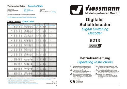
Technische Daten<br />
Technical Data<br />
Datenformat Data format<br />
Motorola<br />
Kontaktbelastbarkeit Max. contact load<br />
2 A<br />
Funktion Function 4 mal 1xUM (bistabil, latching)<br />
Wir wünschen Ihnen viel Spaß mit Ihrer Modellanlage.<br />
We wish that you have much fun with your model railway.<br />
Code-Tabelle Code Table<br />
1 2 1 2<br />
Gruppe Nummer Adresse Decoder Schalter auf On Gruppe Nummer Adresse Decoder Schalter auf On<br />
Group Number Address Decoder Switches set on Group Number Address Decoder Switches set on<br />
1 1 - 4 1 - 4 1 - 2 3 - 5 - 7 - 11 1 - 4 161 - 164 41 - - - 4 - 6 - 8<br />
1 5 - 8 5 - 8 2 - - 3 - 5 - 7 - 11 5 - 8 165 - 168 42 1 - - - - 6 - 8<br />
1 9 - 12 9 - 12 3 1 - - 4 5 - 7 - 11 9 - 12 169 - 172 43 - 2 - - - 6 - 8<br />
1 13 - 16 13 - 16 4 - 2 - 4 5 - 7 - 11 13 - 16 173 - 176 44 - - - - - 6 - 8<br />
2 1 - 4 17 - 20 5 - - - 4 5 - 7 - 12 1 - 4 177 - 180 45 1 - 3 - - - - 8<br />
2 5 - 8 21 - 24 6 1 - - - 5 - 7 - 12 5 - 8 181 - 184 46 - 2 3 - - - - 8<br />
2 9 - 12 25 - 28 7 - 2 - - 5 - 7 - 12 9 - 12 185 - 188 47 - - 3 - - - - 8<br />
2 13 - 16 29 - 32 8 - - - - 5 - 7 - 12 13 - 16 189 - 192 48 1 - - 4 - - - 8<br />
3 1 - 4 33 - 36 9 1 - 3 - - 6 7 - 13 1 - 4 193 - 196 49 - 2 - 4 - - - 8<br />
3 5 - 8 37 - 40 10 - 2 3 - - 6 7 - 13 5 - 8 197 - 200 50 - - - 4 - - - 8<br />
3 9 - 12 41 - 44 11 - - 3 - - 6 7 - 13 9 - 12 201 - 204 51 1 - - - - - - 8<br />
3 13 - 16 45 - 48 12 1 - - 4 - 6 7 - 13 13 - 16 205 - 208 52 - 2 - - - - - 8<br />
4 1 - 4 49 - 52 13 - 2 - 4 - 6 7 - 14 1 - 4 209 - 212 53 - - - - - - - 8<br />
4 5 - 8 53 - 56 14 - - - 4 - 6 7 - 14 5 - 8 213 - 216 54 1 - 3 - 5 - - -<br />
4 9 - 12 57 - 60 15 1 - - - - 6 7 - 14 9 - 12 217 - 220 55 - 2 3 - 5 - - -<br />
4 13 - 16 61 - 64 16 - 2 - - - 6 7 - 14 13 - 16 221 - 224 56 - - 3 - 5 - - -<br />
5 1 - 4 65 - 68 17 - - - - - 6 7 - 15 1 - 4 225 - 228 57 1 - - 4 5 - - -<br />
5 5 - 8 69 - 72 18 1 - 3 - - - 7 - 15 5 - 8 229 - 232 58 - 2 - 4 5 - - -<br />
5 9 - 12 73 - 76 19 - 2 3 - - - 7 - 15 9 - 12 233 - 236 59 - - - 4 5 - - -<br />
5 13 - 16 77 - 80 20 - - 3 - - - 7 - 15 13 - 16 237 - 240 60 1 - - - 5 - - -<br />
6 1 - 4 81 - 84 21 1 - - 4 - - 7 - 16 1 - 4 241 - 244 61 - 2 - - 5 - - -<br />
6 5 - 8 85 - 88 22 - 2 - 4 - - 7 - 16 5 - 8 245 - 248 62 - - - - 5 - - -<br />
6 9 - 12 89 - 92 23 - - - 4 - - 7 - 16 9 - 12 249 - 252 63 1 - 3 - - 6 - -<br />
6 13 - 16 93 - 96 24 1 - - - - - 7 - 16 13 - 16 253 - 256 64 - 2 3 - - 6 - -<br />
7 1 - 4 97 - 100 25 - 2 - - - - 7 - - - 257 - 260 65 - - 3 - - 6 - -<br />
7 5 - 8 101 - 104 26 - - - - - - 7 - - - 261 - 264 66 1 - - 4 - 6 - -<br />
7 9 - 12 105 - 108 27 1 - 3 - 5 - - 8 - - 265 - 268 67 - 2 - 4 - 6 - -<br />
7 13 - 16 109 - 112 28 - 2 3 - 5 - - 8 - - 269 - 272 68 - - - 4 - 6 - -<br />
8 1 - 4 113 - 116 29 - - 3 - 5 - - 8 - - 273 - 276 69 1 - - - - 6 - -<br />
8 5 - 8 117 - 120 30 1 - - 4 5 - - 8 - - 277 - 280 70 - 2 - - - 6 - -<br />
8 9 - 12 121 - 124 31 - 2 - 4 5 - - 8 - - 281 - 284 71 - - - - - 6 - -<br />
8 13 - 16 125 - 128 32 - - - 4 5 - - 8 - - 285 - 288 72 1 - 3 - - - - -<br />
9 1 - 4 129 - 132 33 1 - - - 5 - - 8 - - 289 - 292 73 - 2 3 - - - - -<br />
9 5 - 8 133 - 136 34 - 2 - - 5 - - 8 - - 293 - 296 74 - - 3 - - - - -<br />
9 9 - 12 137 - 140 35 - - - - 5 - - 8 - - 297 - 300 75 1 - - 4 - - - -<br />
9 13 - 16 141 - 144 36 1 - 3 - - 6 - 8 - - 301 - 304 76 - 2 - 4 - - - -<br />
10 1 - 4 145 - 148 37 - 2 3 - - 6 - 8 - - 305 - 308 77 - - - 4 - - - -<br />
10 5 - 8 149 - 152 38 - - 3 - - 6 - 8 - - 309 - 312 78 1 - - - - - - -<br />
10 9 - 12 153 - 156 39 1 - - 4 - 6 - 8 - - 313 - 316 79 - 2 - - - - - -<br />
10 13 - 16 157 - 160 40 - 2 - 4 - 6 - 8 - - 317 - 320 80 1 - 3 - 5 - 7 -<br />
Die im grauen Kasten befindlichen Adressen sind nur mit der Uhlenbrock Intellibox zu erreichen, nicht mit Märklin <strong>Digital</strong>.<br />
The addresses shown in the gray box are only usable with the Uhlenbrock Intellibox, not with Märklin <strong>Digital</strong>.<br />
1<br />
Diese Adresse ist für die Anwender von WIN-DIGIPET bestimmt.<br />
This address is intended for the user of WIN-DIGIPET.<br />
2<br />
Diese Decodernummer ist für die Anwender der Uhlenbrock Intellibox.<br />
Stand 04<br />
This decoder number is intended for the users of the Uhlenbrock Intellibox.<br />
Sachnummer: 98471<br />
8<br />
<strong><strong>Digital</strong>er</strong><br />
<strong>Schaltdecoder</strong><br />
<strong>Digital</strong> <strong>Switching</strong><br />
Decoder<br />
<strong>5213</strong><br />
<strong>Betriebsanleitung</strong><br />
Operating Instructions<br />
D Dieses Produkt ist kein Spielzeug.<br />
Nicht geeignet für Kinder unter 14<br />
Jahren! Anleitung aufbewahren!<br />
GB This product is not a toy.<br />
Not suitable for children under 14<br />
years! Keep instructions!<br />
F Ce produit n'est pas un jouet. Ne<br />
convient pas aux enfants de moins<br />
de 14 ans! Conservez cette notice<br />
d’instructions!<br />
gemäß<br />
EG-Richtlinie<br />
89/336/EWG<br />
Viessmann<br />
Modellspielwaren GmbH<br />
NL Dit produkt is geen speelgoed. Niet<br />
geschikt voor kinderen onder 14 jaar!<br />
Gebruiksaanwijzing bewaren!<br />
I Questo prodotto non è un giocattolo.<br />
Non adatto a bambini al di sotto dei 14<br />
anni! Conservare instruzioni per l’uso!<br />
E Esto no es un juguete. No<br />
recomendado para menores de 14<br />
años! Conserva las instrucciones de<br />
servicio!<br />
1
Der digitale <strong>Schaltdecoder</strong> <strong>5213</strong> von viessmann besitzt 4 separat ansteuerbare Umschalter,<br />
welche zum Schalten von z.B. Modell-Leuchten, Lichtsignalen oder Motoren eingesetzt werden<br />
können. Auch Gleisabschnitte können hiermit stromlos geschaltet werden, z.B. zur Realisierung<br />
von Blockabschnitten.<br />
Der <strong>Schaltdecoder</strong> ist kompatibel zum Motorola-Datenformat und kann somit vom Märklin <strong>Digital</strong>~<br />
- System (mit dem Keyboard, Switchboard oder auch dem Interface) sowie der Uhlenbrock<br />
Intellibox angesteuert werden .<br />
Hierzu muß der Decoder auf eine Adresse eingestellt werden, welche ihn 4 aufeinanderfolgenden<br />
Tastenpaaren eines Switch- oder Keyboards zuordnet. Dieses erfolgt anhand der dieser<br />
Anleitung angefügten Tabelle. Die kleinen Miniaturschalter des achtfachen Codierschalters am<br />
<strong>Schaltdecoder</strong> werden am einfachsten mit einem kleinen Schraubendreher oder einem Kugelschreiber<br />
mit eingezogener Mine verschoben.<br />
Beispiel: Codierschaltereinstellung (Keyboard Nr. 8, Taster 9 - 12)<br />
Example: Setting of the code switches (Keyboard No. 8, keys 9 - 12)<br />
2<br />
Tabelle - 2 - 4 5 - - 8<br />
Table - 2 - 4 5 - - 8<br />
Zu weiteren<br />
Decodern<br />
to further<br />
decoders<br />
rot<br />
red<br />
rot<br />
red<br />
4 3<br />
1 2<br />
Funktionsdiagramm<br />
Functional Diagram<br />
The switching decoder viessmann <strong>5213</strong> has got four separately switchable DPDT switches<br />
which can be used for example to switch model lamps, colour light signals or motors. They can<br />
also be used for switching the current of rail sections (e.g. for a blocking system).<br />
The decoder uses the Motorola data format and so it can be used with the system Märklin<br />
<strong>Digital</strong>~ (you can control it by the Interface, the Keyboard or the Switchboard, too) or the Uhlenbrock<br />
Intellibox.<br />
The 5211 has to be set to an address, which classes it with 4 succeeding pairs of switches of a<br />
Switchboard, a Keyboard or the Intellibox. You can see it in the table at the end of this instructions.<br />
The eight miniature switches are switchable by using a small screwdriver or a ball pen<br />
with a removed cartridge.<br />
Adresse<br />
braun<br />
brown<br />
viessmann<br />
<strong>Schaltdecoder</strong> <strong>5213</strong><br />
von der<br />
Zentraleinheit<br />
bzw. vom Gleis<br />
from the central<br />
unit resp. from the<br />
rail<br />
Die Umschaltkontakte 1 bis 4 werden über je ein Tastenpaar des Keyboards umgeschaltet. Ein<br />
Druck auf die jeweilige grüne Taste verbindet die mittlere graue Buchse mit der grünen Buchse<br />
des zugehörigen Umschalters, ein Druck auf die rote Taste hingegen mit der jeweiligen roten<br />
Buchse. Die entsprechenden Schalterstellungen bleiben auch beim Abschalten der Anlage im<br />
Decoder gespeichert. Ein Anwendungsbeispiel besteht in der Ansteuerung von viessmann<br />
Lichtsignalen und von viessmann Lampen:<br />
Zugbeeinflussung<br />
Automatic Train Control<br />
Wenn neben der Ansteuerung der Signal-LEDs eine Zugbeeinflussung erforderlich ist, so empfiehlt<br />
es sich, zwei <strong>Schaltdecoder</strong> auf dieselbe Adresse einzustellen. Gleichnamige Ausgangskontakte<br />
beider Decoder schalten dann simultan. Während ein Decoder gemäß vorstehender<br />
Diagramme die Ansteuerung der Lichtsignale übernimmt, kann der zweite für die Zugbeeinflussung<br />
verwendet werden.<br />
Wenn mit den Schaltkontakten des Decoders <strong>5213</strong> Gleisabschnitte stromlos geschaltet werden<br />
sollen, welche digitalen Fahrstrom führen, so müssen die Schaltkontakte jeweils mit einem<br />
Widerstand 1,5 kOhm/ 0,25 Watt überbrückt werden. Dieses ist notwendig, damit die Lokomotiven<br />
auch beim Halt ihre <strong>Digital</strong>information behalten.<br />
If you want to switch signal LED's and the track current for automatic train control, you have to<br />
use two decoders <strong>5213</strong> and set them to the same address. So the outputs with the same number<br />
are switched simultaneously. So you can use one decoder to switch the color light signals<br />
like shown in the diagrams above. The other decoder then can be used for the automatic train<br />
control.<br />
If you want to control digital track power current by the switching contacts of the decoder <strong>5213</strong>,<br />
you have to bridge the contacts by a resistor of 1.5k ohms/0.25 watts.This is necessary to ensure<br />
that the locomotive keep the digital information, even when it stops.<br />
Zum Steuern von viessmann-Formsignalen eignet sich der Magnetartikeldecoder 5211. Dieser<br />
bietet neben einem Kurzschluß-Schutz auch die Möglichkeit, den Schaltstrom einem separaten<br />
Trafo zu entnehmen und somit die <strong>Digital</strong>stromquelle (den "Booster") zu entlasten.<br />
To control the viessmann-semaphores you can use the decoder for electromagnetic devices<br />
5211. It has got a short circuit protection and allows to take the switching current from a<br />
separate transformer. So the digital booster will be relieved.<br />
7
Vorsignal (3 Begriffe)<br />
Distant Signal (3 aspects)<br />
Funktionen: Taster 1 + 2 rot Vorsignal auf Vr0 ("Fahrt erwarten")<br />
Functions: Button 1 + 2 red distant signal to Vr0 ("expect go")<br />
Taster 1 + 2 grün Vorsignal auf Vr1 ("Halt erwarten")<br />
Button 1 + 2 green<br />
Taster 1 grün und<br />
distant signal to Vr1 ("expect stop")<br />
Taster 2 rot<br />
Button 1 green and<br />
Vr2 ("Langsamfahrt erwarten")<br />
Button 2 red distant signal to Vr2 ("expect reduced speed")<br />
Bemerkung: Wenn sich das Vorsignal am Mast eines Hauptsignals befindet, so ist der im<br />
obigen Anschlußplan mit X bezeichnete Anschluß nicht mit der Signal-Betriebsspannung<br />
(16 V ~/=) zu verbinden (gestrichelte Leitung), sondern mit<br />
dem mit “X” gekennzeichneten Anschlußpunkt des Hauptsignal-Anschlußplans.<br />
Hierdurch wird das Vorsignal automatisch abgeschaltet, wenn das<br />
Hauptsignal am gleichen Mast "Zughalt" anzeigt (Dunkeltastung).<br />
Annotation: If the distant signal is mounted at the mast of a home signal, the connector with<br />
the label "X" may not be connected with the supply voltage (16V AC/DC) but<br />
with the same labeled connector of the main signal's circuit diagram. Then the<br />
distant signal will automatically switched off if the home signal indicates "stop"<br />
(dark switching).<br />
6<br />
braun<br />
brown<br />
rot<br />
red<br />
gelb<br />
yellow<br />
grün<br />
green<br />
von der Zentraleinheit<br />
bzw. vom Gleis<br />
from the central unit<br />
resp. from the rail<br />
rot<br />
red<br />
Adresse<br />
braun<br />
brown<br />
4003, ½4004,<br />
4010, ½4014, ½4015, ½4016,<br />
4410, ½4414, ½4415, ½4416,<br />
4810,<br />
4910, ½4914, ½4915, ½4916<br />
4 3<br />
viessmann<br />
<strong>Schaltdecoder</strong> <strong>5213</strong><br />
1 2<br />
grün<br />
green<br />
gelb<br />
yellow<br />
X<br />
gn2<br />
ge2<br />
gn1<br />
ge1<br />
ge1<br />
ge2<br />
grün<br />
green<br />
~-<br />
16 V<br />
AC/DC<br />
gn1<br />
gn2<br />
z.B. 6090 4002, 4011, ½4014,<br />
4411, ½4414, 4811,<br />
4911, ½4914<br />
rt<br />
von der Zentraleinheit<br />
bzw. vom Gleis<br />
from the central unit<br />
resp. from the rail<br />
Adresse<br />
Achtung!<br />
4 3<br />
viessmann<br />
<strong>Schaltdecoder</strong> <strong>5213</strong><br />
1 2<br />
rot<br />
rt<br />
red rot<br />
red<br />
braun<br />
brown<br />
gelb<br />
yellow<br />
Funktionen: Taster 1 rot Lampen an<br />
Functions: Button 1 red lamps on<br />
Taster 1 grün Lampen aus<br />
Button 1 green lamps off<br />
Taster 2 rot Blocksignal auf Hp0 („Halt“)<br />
Button 2 red block signal to Hp0 (“stop“)<br />
Taster 2 grün Blocksignal auf Hp1 („Fahrt“)<br />
Button 2 green block signal to Hp1 (“go“)<br />
The DPDT switches 1 to 4 are each switched by a pair of keys of the Märklin Keyboard. If you<br />
push the green key then the corresponding gray middle plug will be connected with the related<br />
green plug of the decoder. If you push the red key, the gray middle plug will be connected with<br />
the red plug. The actual setting of the internal DPDT switches will also be stored after power<br />
down. Above you can see two examples: The controling of viessmann colour light signals and<br />
the switching of viessmann lamps.<br />
* Der Anschlußpunkt „X“ dient der Vorsignalsteuerung (Dunkeltastung), wenn dieses am Mast des<br />
Blocksignals angebracht ist, d.h. bei 4014, 4414 und 4914 (siehe weiter hinten).<br />
The connector point “X“ serves to control the distant signal (dark switching), if it is mounted at the<br />
same mast as the block signal (4014, 4414 and 4914)<br />
Attention!<br />
Alle Anschlußarbeiten sind nur bei abgeschalteter Betriebsspannung<br />
durchzuführen!<br />
Make sure that the power supply is switched off when you connect the wires !<br />
Die Stromquellen müssen so abgesichert sein, daß es im Falle eines Kurzschlusses<br />
nicht zum Kabelbrand kommen kann. Verwenden Sie nur<br />
handelsübliche und nach VDE/EN gefertigte Modellbahntransformatoren!<br />
The power sources must be protected to prevent the risk of burning wires. Only<br />
use VDE/EN tested special model train transformers for the power supply!<br />
~-<br />
gn<br />
16 V<br />
AC/DC<br />
grün<br />
green<br />
gn<br />
braun<br />
brown<br />
rot<br />
red<br />
gelb<br />
yellow<br />
grün<br />
green<br />
X*<br />
3
Im Folgenden finden Sie Anschlußtips für weitere viessmann Lichtsignale:<br />
In the following you can see how to connect furthe viessmann colour light signals:<br />
Einfahrsignal (3 Begriffe)<br />
Entry Signal (3 aspects)<br />
von der Zentraleinheit<br />
bzw. vom Gleis<br />
from the central unit<br />
resp. from the rail<br />
Funktionen: Taster 1 rot Einfahrsignal auf Hp0 („Halt“)<br />
Functions: Button 1 red entry signal to Hp0 (“stop“)<br />
Taster 1 grün Einfahrsignal auf Hp1 / Hp2<br />
Button 1 green entry signal to Hp1 / Hp2<br />
Taster 2 rot Einfahrsignal auf Hp2 (“Langsamfahrt“)<br />
Button 2 red entry signal to Hp2 (“reduced speed“)<br />
Taster 2 grün Einfahrsignal auf Hp1 („Fahrt“)<br />
Button 2 green entry signal to Hp1 (“go“)<br />
Bemerkung: Um von Hp0 nach Hp1 oder Hp2 zu schalten, zuerst mit dem Tastenpaar 2<br />
Hp1 oder Hp2 vorwählen. Erst dann Taster 1 grün betätigen!<br />
Annotation: To switch from Hp0 to Hp1 or Hp2 please select at first between Hp1 and Hp2<br />
with the button pair 2. After this press the button 1 green!<br />
* Der Anschlußpunkt „X“ dient der Vorsignalsteuerung (Dunkeltastung), wenn dieses am Mast des<br />
Einfahrsignals angebracht ist, d.h. bei 4015, 4415, 4915 und 4004 (siehe weiter hinten).<br />
The connector point “X“ serves to control the distant signal (dark switching), if it is mounted at the<br />
same mast as the entry signal (4015, 4415, 4915 and 4004).<br />
4<br />
braun<br />
brown<br />
rot<br />
red<br />
gelb<br />
yellow<br />
grün<br />
green<br />
rot<br />
red<br />
Adresse<br />
braun<br />
brown<br />
4 3<br />
viessmann<br />
<strong>Schaltdecoder</strong> <strong>5213</strong><br />
1 2<br />
~-<br />
16 V<br />
AC/DC<br />
4001, ½4004,<br />
4012, ½4015,<br />
4412, ½4415,<br />
4812,<br />
4912, ½4915<br />
rt<br />
gn<br />
ge<br />
Ausfahrsignal (4 Begriffe)<br />
Exit Signal (4 aspects)<br />
braun<br />
brown<br />
rot<br />
red<br />
gelb<br />
yellow<br />
von der Zentraleinheit<br />
bzw. vom Gleis<br />
from the central unit<br />
resp. from the rail<br />
Adresse<br />
braun<br />
brown<br />
4 3<br />
viessmann<br />
<strong>Schaltdecoder</strong> <strong>5213</strong><br />
1 2<br />
grün<br />
green<br />
rt<br />
rot<br />
red<br />
gn<br />
gelb<br />
yellow<br />
ge<br />
grün green<br />
X*<br />
rot<br />
red<br />
rt1<br />
rot<br />
red<br />
gn ge<br />
grün green<br />
gelb<br />
yellow<br />
16 V<br />
AC/DC<br />
4005,<br />
4013, ½4016,<br />
4413, ½4416,<br />
4813,<br />
4913, ½4916<br />
Funktionen: Taster 1 rot Ausfahrsignal auf Sh1 / Hp00<br />
Functions: Button 1 red exit signal to Hp00 / Sh1<br />
Taster 1 grün Ausfahrsignal auf Hp1 / Hp2<br />
Button 1 green exit signal to Hp1 / Hp2<br />
Taster 2 rot Ausfahrsignal auf Hp2 (“Langsamfahrt“)<br />
Button 2 red exit signal to Hp2 (“reduced speed“)<br />
Taster 2 grün Ausfahrsignal auf Hp1 („Fahrt“)<br />
Button 2 green exit signal to Hp1 (“go“)<br />
Taster 3 rot Ausfahrsignal auf Hp00 („Halt“)<br />
Button 3 red exit signal to Hp00 (“stop“)<br />
Taster 3 grün Ausfahrsignal auf Hp0/Sh1 („Rangierfahrt“)<br />
Button 3 green exit signal to Hp0/Sh1 (“shunting maneuver“)<br />
Bemerkung: Um von Hp00 oder Hp0/Sh1 nach Hp1 oder Hp2 zu schalten, zuerst mit dem<br />
Tastenpaar 2 Hp1 oder Hp2 bzw. mit dem Tastenpaar 3 Hp00 oder Hp0/Sh1<br />
vorwählen. Erst dann eine der Tasten 1 (grün oder rot) betätigen!<br />
Annotation: To switch from Hp00 or Hp0/Sh1 to Hp1 or Hp2 please choose at first between<br />
Hp1 and Hp2 with the button pair 2 resp. between Hp00 and Hp0/Sh1 with the<br />
button pair 2. After this press one of the button 1 (green or red)!<br />
* Der Anschlußpunkt „X“ dient der Vorsignalsteuerung (Dunkeltastung), wenn dieses am Mast des<br />
Ausfahrsignals angebracht ist, d.h. bei 4016, 4416, 4916 (siehe weiter hinten).<br />
The connector point “X“ serves to control the distant signal (dark switching), if it is mounted at the<br />
same mast as the exit signal (4016, 4416, 4916).<br />
~-<br />
rot<br />
red<br />
rot<br />
red<br />
gn<br />
rt1<br />
ge<br />
ws<br />
rt2<br />
rt2<br />
ws<br />
X*<br />
5