

Switch Motor - Viessmann Modellspielwaren GmbH
Switch Motor - Viessmann Modellspielwaren GmbH
Switch Motor - Viessmann Modellspielwaren GmbH

Sie wollen auch ein ePaper? Erhöhen Sie die Reichweite Ihrer Titel.
YUMPU macht aus Druck-PDFs automatisch weboptimierte ePaper, die Google liebt.
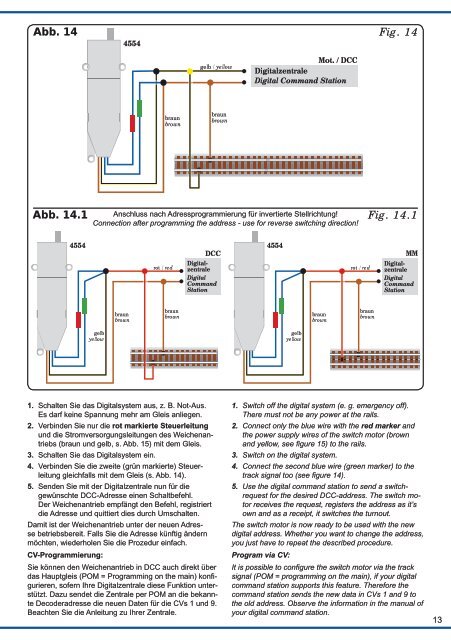
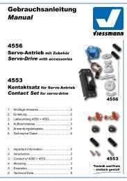
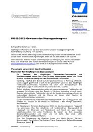
Abb. 14<br />
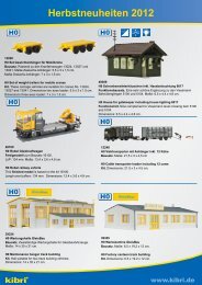
Abb. 14.1<br />
4554<br />
gelb<br />
yellow<br />
braun<br />
brown<br />
4554<br />
braun<br />
brown<br />
rot / red<br />
braun<br />
brown<br />
gelb / yellow<br />
braun<br />
brown<br />
DCC<br />
Digitalzentrale<br />
Digital<br />
Command<br />
Station<br />
1. Schalten Sie das Digitalsystem aus, z. B. Not-Aus.<br />
Es darf keine Spannung mehr am Gleis anliegen.<br />
2. Verbinden Sie nur die rot markierte Steuerleitung<br />
und die Stromversorgungsleitungen des Weichenantriebs<br />
(braun und gelb, s. Abb. 15) mit dem Gleis.<br />
3. Schalten Sie das Digitalsystem ein.<br />
4. Verbinden Sie die zweite (grün markierte) Steuerleitung<br />
gleichfalls mit dem Gleis (s. Abb. 14).<br />
5. Senden Sie mit der Digitalzentrale nun für die<br />
gewünschte DCC-Adresse einen Schaltbefehl.<br />
Der Weichenantrieb empfängt den Befehl, registriert<br />
die Adresse und quittiert dies durch Umschalten.<br />
Damit ist der Weichenantrieb unter der neuen Adresse<br />
betriebsbereit. Falls Sie die Adresse künftig ändern<br />
möchten, wiederholen Sie die Prozedur einfach.<br />
CV-Programmierung:<br />
Sie können den Weichenantrieb in DCC auch direkt über<br />
das Hauptgleis (POM = Programming on the main) konfigurieren,<br />
sofern Ihre Digitalzentrale diese Funktion unterstützt.<br />
Dazu sendet die Zentrale per POM an die bekannte<br />
Decoderadresse die neuen Daten für die CVs 1 und 9.<br />
Beachten Sie die Anleitung zu Ihrer Zentrale.<br />
Mot. / DCC<br />
Digitalzentrale<br />
Digital Command Station<br />
Anschluss nach Adressprogrammierung für invertierte Stellrichtung!<br />
Connection after programming the address - use for reverse switching direction!<br />
4554<br />
gelb<br />
yellow<br />
braun<br />
brown<br />
rot / red<br />
braun<br />
brown<br />
Fig. 14<br />
Fig. 14.1<br />
MM<br />
Digitalzentrale<br />
Digital<br />
Command<br />
Station<br />
1. <strong>Switch</strong> off the digital system (e. g. emergency off).<br />
There must not be any power at the rails.<br />
2. Connect only the blue wire with the red marker and<br />
the power supply wires of the switch motor (brown<br />
and yellow, see figure 15) to the rails.<br />
3. <strong>Switch</strong> on the digital system.<br />
4. Connect the second blue wire (green marker) to the<br />
track signal too (see figure 14).<br />
5. Use the digital command station to send a switchrequest<br />
for the desired DCC-address. The switch motor<br />
receives the request, registers the address as it’s<br />
own and as a receipt, it switches the turnout.<br />
The switch motor is now ready to be used with the new<br />
digital address. Whether you want to change the address,<br />
you just have to repeat the described procedure.<br />
Program via CV:<br />
It is possible to configure the switch motor via the track<br />
signal (POM = programming on the main), if your digital<br />
command station supports this feature. Therefore the<br />
command station sends the new data in CVs 1 and 9 to<br />
the old address. Observe the information in the manual of<br />
your digital command station.<br />
13

![Interactive News [pdf]](https://img.yumpu.com/13782861/1/190x107/interactive-news-pdf.jpg?quality=85)
