


Switch Motor - Viessmann Modellspielwaren GmbH
Switch Motor - Viessmann Modellspielwaren GmbH
Switch Motor - Viessmann Modellspielwaren GmbH

Erfolgreiche ePaper selbst erstellen
Machen Sie aus Ihren PDF Publikationen ein blätterbares Flipbook mit unserer einzigartigen Google optimierten e-Paper Software.
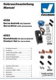
Märklin C-Gleis (DKW)<br />
Hebel: 1<br />
Montage: in Bettung<br />
1. Montieren Sie den Hebel gemäß Abbildung 3.1 (links)<br />
im Weichenantrieb und verschließen Sie anschließend<br />
das Gehäuse wieder.<br />
2. Bringen Sie die Doppelkreuzungsweiche in die zum<br />
Antrieb passende Stellung (Der Hebel des Weichenantriebs<br />
muss in den Hebel der DKW greifen).<br />
3. Legen Sie den Weichenantrieb gemäß Abbildung 5 in<br />
die Bettung der Weiche und fixieren Sie ihn mit den<br />
passenden Schrauben 2 x Nr. 13.<br />
Abb. 5<br />
5.1 5.2<br />
Roco-Line (ohne Bettung)<br />
Hebel: 8 und 9<br />
Montage: oberflur, neben Gleis<br />
1. Montieren Sie die Hebel gemäß Abbildung 6.1 im Weichenantrieb<br />
und verschließen Sie anschließend das<br />
Gehäuse wieder.<br />
2. Entfernen Sie den markierten Befestigungsring an der<br />
Einkerbung mit einem scharfen Messer.<br />
3. Bringen Sie die Weiche in die zum Antrieb passende<br />
Stellung (Der Hebel des Weichenantriebs muss in den<br />
Hebel der Weiche greifen).<br />
4. Montieren Sie den Antrieb neben der Weiche (Abb.<br />
6.2) und fixieren Sie ihn mit den passenden<br />
Distanzhülsen und Schrauben 2 x Nr. 13.<br />
Bei Verwendung der EKW und der DKW entfernen Sie<br />
bitte den Steg im Hebel 9 (Abb. 9.1) und montieren Sie<br />
den Antrieb mit dem Deckel nach unten.<br />
Abb. 6<br />
Märklin C-track (Double Slip <strong>Switch</strong>)<br />
Lever: 1<br />
Mounting: Into bed of ballast<br />
1. Mount lever 1 as shown in figure 3.1 into the switch<br />
motor. After mounting the lever, close the casing with<br />
the cover.<br />
2. Bring the <strong>Switch</strong> into the corresponding position of the<br />
switch motor (the lever of the switch motor has to get<br />
connected with the lever of the switch).<br />
3. Put the switch motor into the intended empty space of<br />
the turnout as shown in figure 5.<br />
Fix the switch motor with the screws 2 x nr. 13.<br />
6.1 6.2 6.3<br />
2,2 x 6 mm<br />
Fig. 5<br />
Roco-Line (without ballast)<br />
Lever: 8 and 9<br />
Mounting: Overground, beside the track<br />
1. Mount lever 1 as shown in figure 6.1 into the switch<br />
motor. After mounting the lever, close the casing with<br />
the cover.<br />
2. Cut off the fastening ring at the notch with a sharp<br />
knife as shown in figure 6.1.<br />
3. Bring the turnout into the corresponding position of the<br />
switch motor (the lever of the switch motor has to get<br />
connected with the lever of the turnout).<br />
4. Mount the switch motor beside the turnout as shown<br />
in figure 6.2. Fix the switch motor with the screws 2 x<br />
nr. 13. Use the distance rolls!<br />
When using a slip switch, cut off the bridge in lever 9 (see<br />
figure 9.1) and mount the switch motor with the cover to<br />
the ground.<br />
Fig. 6<br />
7


![Interactive News [pdf]](https://img.yumpu.com/13782861/1/190x107/interactive-news-pdf.jpg?quality=85)
