Cockpit Cover BMW F650(Twin)/800GS - Touratech-USA
Cockpit Cover BMW F650(Twin)/800GS - Touratech-USA
Cockpit Cover BMW F650(Twin)/800GS - Touratech-USA

Erfolgreiche ePaper selbst erstellen
Machen Sie aus Ihren PDF Publikationen ein blätterbares Flipbook mit unserer einzigartigen Google optimierten e-Paper Software.
01-048-0430-0<br />
DE20080424<br />
1<br />
2<br />
3<br />
Montage:<br />
Juni 2008<br />
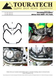
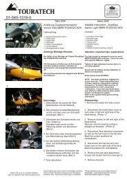
Anleitung:Instrumentenabdeckung<br />
<strong>BMW</strong> F 650(<strong>Twin</strong>)/800 GS<br />
Lieferumfang:<br />
1x Instrumentenabdeckung<br />
1x Buchse klein<br />
1x Buchse mittel<br />
1x Buchse gross<br />
1 x Bordnetzsteckdose<br />
2 x Kabelabzweiger<br />
4 x Kabelverbinder Buchse<br />
2 x Anschlussleitung (rot u. Schwarz)<br />
1 x Sicherungshalter<br />
1 x Flachsicherungseinsatz 15A blau<br />
1 x Moosgummistreifen (10mm x 15mm)<br />
1 x Moosgummistreifen (10mm x 70mm)<br />
1 x Isolierschlauch<br />
Achtung! Wichtige Hinweise<br />
Bei allen Arbeiten Zündung aus<br />
1. Demontieren Sie zuerst die<br />
Frontscheibe. Dazu entfernen Sie die<br />
vorderen und seitlichen Schrauben der<br />
Scheibe (siehe Bild 1 u. 2)<br />
DIN EN ISO 9001:2000<br />
Zertifikat 15 100 42285<br />
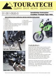
Installation Instruction: <strong>Cockpit</strong><br />
<strong>Cover</strong> <strong>BMW</strong> <strong>F650</strong>(<strong>Twin</strong>)/<strong>800GS</strong><br />
Contains:<br />
Assembly:<br />
June 2008<br />
1 x <strong>Cockpit</strong> cover<br />
1 x Bushing small<br />
1 x Bushing medium<br />
1 x Bushing large<br />
1 x Accessory outlet socket<br />
2 x Cable connector<br />
4 x Blade connector<br />
2 x Connection cable (red and black)<br />
1 x Fuse holder<br />
1 x Blade fulse 15A blue<br />
1 x Addhesive rubber (10mm x 15mm)<br />
1 x Addhesive rubber (10mm x 70mm)<br />
1 x Wire isolation tubing<br />
Attention! Important tip, information:<br />
Turn ignition off and disconnect<br />
battery during installation!<br />
1. Disassemble the windscreen by<br />
removing the screws at front and on the<br />
sides (see photo 1 and 2).<br />
3<br />
4<br />
5<br />
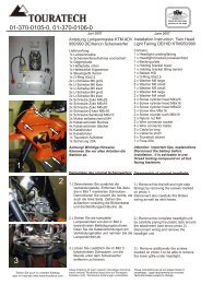
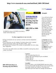
2. Für die leichtere Demontage entfernen<br />
Sie die Schrauben links und rechts an der<br />
Scheinwerfer Halterung (siehe Bild 3).<br />
Nun können Sie den Scheinwerfer nach<br />
vorne schieben und ihn vorsichtig auf den<br />
Kotflügel legen (Achtung! Bitte ein<br />
sauberes Tuch unterlegen um Kratzer im<br />
Lack zu vermeiden).<br />
3. Wenn Sie nun von vorne auf die<br />
<strong>Cockpit</strong>einheit schauen sehen sie 3<br />
Schnellverschlüsse (Clips) welche die<br />
<strong>Cockpit</strong>einheit festklemmen (siehe Bild 4).<br />
Entfernen Sie diese indem Sie sie zur<br />
geschlossenen Seite abziehen. Am besten<br />
geht dies mit einer kleinen Spitzzange).<br />
Nun können Sie das gesamte <strong>Cockpit</strong><br />
nach hinten abziehen.<br />
4. Ziehen Sie den Stecker vom <strong>Cockpit</strong> ab<br />
indem sie die Sicherung der Haltelaschen<br />
auf beiden Seiten etwas<br />
zusammendrücken (siehe Bild 5).<br />
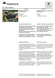
2. For easier disassembly remove also<br />
the left and right screws of the headlight<br />
bracket (see photo 3).<br />
Pull the headlight forward and set it<br />
carefully on the front fender (Attention!<br />
Use cloth under headlight to avoid<br />
scratching on fender paint!)<br />
3. Remove the three quick release<br />
circlips that hold the instrument unit<br />
behind the cockpit (see photo 4).<br />
Needle nose pliers are a good tool for<br />
clips removal.<br />
Pull then the complete instrument unit<br />
back and off.<br />
4. Disconnect the cockpit plug by<br />
pressing the latches together on the<br />
sides (see photo 5).<br />
Sehen Sie auch in unserem Katalog<br />
oder im Internet unter www.touratech.com<br />
Diese Anleitung ist nach unserem derzeitigen Kenntnisstand<br />
verfasst. Rechtliche Ansprüche auf Richtigkeit<br />
bestehen nicht. Technische Änderungen vorbehalten.<br />
These instructions are at our present level of<br />
knowledge. Legal requirements for correctness do not<br />
exist. Technical issues subject to change.
01-048-0430-0<br />
DE20070122<br />
Juni 2008<br />
June 2008<br />
DIN EN ISO 9001:2000<br />
Zertifikat 15 100 42285<br />
6<br />
1<br />
7<br />
3<br />
2<br />
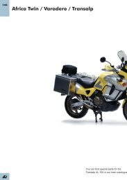
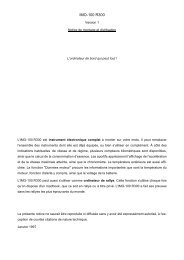
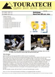
5. Nun legen Sie, wie im Bild 6 gezeigt,<br />
die Abstandshülsen hinten auf das<br />
<strong>Cockpit</strong>. 1 kleine Buchse, 2 mittlere<br />
Buchse, 3 große Buchse.<br />
6.Bevor Sie nun die Instrumentenblende<br />
auflegen Schrauben Sie die Steckdose<br />
wie in Bild 7 in der Blende fest.<br />
7 Kleben Sie die Moosgummistreifen wie<br />
in Bild 8 beschrieben auf den<br />
<strong>Cockpit</strong>träger.<br />
5. Set now the spacer bushing behind<br />
the instrument unit as shown in photo 6.<br />
1 small bushing, 2 medium bushing and<br />
3 large bushing.<br />
6. Install the accessory outlet on on the<br />
cockpit cover as shown in photo 7.<br />
7. Apply the addhesive rubber strips as<br />
shown in photo 8 on the cockpit bracket.<br />
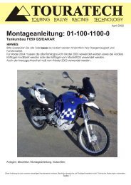
8 Nun legen Sie die Blende wie in Bild 9<br />
gezeigt auf.<br />
8. Set the cockpit cover on the back of<br />
the instrument unit as shown in photo 9.<br />
8<br />
9<br />
9. Stecken Sie das <strong>Cockpit</strong> wieder in die<br />
dafür vorgesehenen Halterungen und<br />
bauen Sie alles wieder in umgekehrter<br />
Reihenfolge zusammen.<br />
9. Reconnect the cockpit plug and<br />
reinstall cockpit unit in reverse order<br />
with the circlips.<br />
10. Der Anschluss der Steckdose an das 10. Connect the accessory outlet using<br />
Bordnetz erfolgt mittels der beiden supplied black and red wires and<br />
beiliegenden Leitungen 1-Ader in rot und connectors.<br />
schwarz. Sie haben die Möglichkeit mit Our preferred wiring option is directly to<br />
den beiden Kabelabzweigern direkt zwei motorcycle battery so outlet can be used<br />
Leitungen anzuzapfen. Bedenken Sie bitte for battery charging for example or to<br />
bei der Wahl der anzuzapfenden run GPS when bike is not running. For<br />
Leitungen, ob die Bordnetzsteckdose mit clarity use the red wire as positive lead<br />
Dauerplus oder über das Zündschloss from the center blade on the back of the<br />
geschaltet mit Strom versorgt werden soll. accessory outlet to battery positive (over<br />
Den Masseanschluss können Sie sowohl fuse holder). Use the black wire as<br />
an einer beliebigen Masseleitung, als ground wire from the outside accessory<br />
auch direkt an der Batterie vornehmen. outlet terminal to ground or battery<br />
Ziehen Sie bitte über die beiden<br />
negative pole.<br />
Anschlussleitungen den beiliegenden Route wires away from moving and hot<br />
Isolierschlauch, um die Leitungen vor parts, through the protective tubing and<br />
Beschädigungen zu schützen.<br />
secure with cable ties.<br />
Sehen Sie auch in unserem Katalog<br />
oder im Internet unter www.touratech.com<br />
Diese Anleitung ist nach unserem derzeitigen Kenntnisstand<br />
verfasst. Rechtliche Ansprüche auf Richtigkeit<br />
bestehen nicht. Technische Änderungen vorbehalten.<br />
These instructions are at our present level of<br />
knowledge. Legal requirements for correctness do not<br />
exist. Technical issues subject to change.