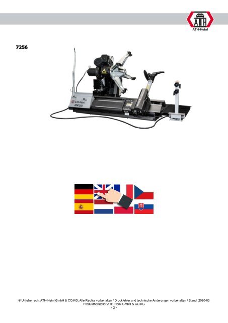
- Seite 1: BEDIENUNGSANLEITUNG / OPERATING INS
- Seite 5 und 6: 1.0 EINLEITUNG 1.1 Allgemeine Infor
- Seite 7 und 8: 1.2.2 Beschreibung Sicherheitseinri
- Seite 9 und 10: 1.3.3 Bedienung der Reifenmontierma
- Seite 11 und 12: Nun mit der Abdrückscheibe die zwe
- Seite 13 und 14: ACHTUNG!!! Bei der Montage kann der
- Seite 15 und 16: 1.5 Maßzeichnung 1020 - 1950 mm 20
- Seite 17 und 18: 2.2 Auspacken und Anheben Entfernen
- Seite 19 und 20: 2.4 Standort Die Maschine sollte vo
- Seite 21 und 22: 2.8 Hydraulischer Anschluss Bevor d
- Seite 23 und 24: Zum Befestigen der Maschine werden
- Seite 25 und 26: 3.2 Grundsätzliche Hinweise Mit de
- Seite 27 und 28: Bodenverankerung Mindestanforderung
- Seite 29 und 30: 4.5 Fehlersuche / Fehleranzeige und
- Seite 31 und 32: Einstellung der Antriebsriemenspann
- Seite 33 und 34: 6.0 ANHANG 6.1 Pneumatik-Schaltplan
- Seite 35 und 36: 6.3 Hydraulik-Schaltplan Y1 Y2 Y3 Y
- Seite 37 und 38: 7.1 Umfang der Produktgarantie •
- Seite 39 und 40: 8.1 Aufstellungs- und Übergabeprot
- Seite 41 und 42: 8.3 Sichtprüfung (Befugte Sachkund
- Seite 43 und 44: Sichtprüfung (Befugte Sachkundige
- Seite 45 und 46: 9.0 NOTIZEN ® Urheberrecht WM SE,
- Seite 47 und 48: OPERATING INSTRUCTIONS ATH 7256
- Seite 49 und 50: 1.1 General Information 1.0 INTRODU
- Seite 51 und 52: 1.2.2. Safety Equipment Description
- Seite 53 und 54:
1.3.3. Operating the tyre mounting
- Seite 55 und 56:
Now remove the second bead with the
- Seite 57 und 58:
WARNING!! During assembly, the moun
- Seite 59 und 60:
1.5 Scale Drawing 1020 - 1950 mm 20
- Seite 61 und 62:
2.2 Unpacking the machine Remove th
- Seite 63 und 64:
2.4 Location The machine should be
- Seite 65 und 66:
2.8 Hydraulic Connection Before the
- Seite 67 und 68:
Impact anchors of at least M12x100
- Seite 69 und 70:
3.2 Basic Information Independent o
- Seite 71 und 72:
Floor anchor Minimum requirement fo
- Seite 73 und 74:
4.5 Troubleshooting / Error Display
- Seite 75 und 76:
Setting the drive belt tension 1. C
- Seite 77 und 78:
6.1 Pneumatic circuit diagram Not r
- Seite 79 und 80:
6.3 Hydraulic circuit diagram Y1 Hy
- Seite 81 und 82:
Dealer address: Company (or custome
- Seite 83 und 84:
This inspection manual (including l
- Seite 85 und 86:
8.2 Inspection Plan Nameplate Quick
- Seite 87 und 88:
Visual inspection (authorised exper
- Seite 89 und 90:
Visual inspection (authorised exper
- Seite 91 und 92:
® Copyright ATH-Heinl GmbH & Co. K
- Seite 93 und 94:
® Copyright ATH-Heinl GmbH & Co. K
- Seite 95 und 96:
MANUEL D'UTILISATION ATH 7256
- Seite 97 und 98:
1.0 INTRODUCTION 1.1 Informations g
- Seite 99 und 100:
1.2.2. Description des dispositifs
- Seite 101 und 102:
1.3.3. Utilisation du démonte-pneu
- Seite 103 und 104:
Démontez ensuite le deuxième talo
- Seite 105 und 106:
ATTENTION ! L'outil de montage risq
- Seite 107 und 108:
1.5 Croquis coté 1020 - 1950 mm 20
- Seite 109 und 110:
2.2 Déballage de la machine Retire
- Seite 111 und 112:
2.4 Lieu La machine doit être tenu
- Seite 113 und 114:
2.8 Raccordement hydraulique Avant
- Seite 115 und 116:
Il est conseiller d'utiliser des ch
- Seite 117 und 118:
3.2 Remarques générales Seules de
- Seite 119 und 120:
Cheville d'ancrage M12 x 100 Instal
- Seite 121 und 122:
4.5 Dépannage / Affichage des déf
- Seite 123 und 124:
Réglage de la tension de la courro
- Seite 125 und 126:
6.0 ANNEXE 6.1 Schéma pneumatique
- Seite 127 und 128:
6.3 Schéma hydraulique Y1 Vérin h
- Seite 129 und 130:
7.1 Étendue de la garantie produit
- Seite 131 und 132:
8.1 Procès-verbal d'installation e
- Seite 133 und 134:
8.3 Contrôle visuel (personne qual
- Seite 135 und 136:
Contrôle visuel (personne qualifi
- Seite 137 und 138:
9.0 NOTICES ® Droit d'auteur ATH-H
- Seite 139 und 140:
NÁVOD K OBSLUZE ATH 7256
- Seite 141 und 142:
1.0 ÚVOD 1.1 Obecné informace TEN
- Seite 143 und 144:
1.2.2. Popis bezpečnostních zař
- Seite 145 und 146:
1.3.3. Obsluha stroje k montáží
- Seite 147 und 148:
Teď pomocí odtlačovacího kotou
- Seite 149 und 150:
POZOR!!! Během montáže může mo
- Seite 151 und 152:
1.5 Rozměrový výkres 1020 - 1950
- Seite 153 und 154:
2.2 Vybalení stroje Sejměte horn
- Seite 155 und 156:
2.4 Umístění Stroj byste měli p
- Seite 157 und 158:
2.8 Hydraulické připojení Před
- Seite 159 und 160:
Pro upevnění stroje doporučujeme
- Seite 161 und 162:
3.2 Zásadní upozornění Stroj sm
- Seite 163 und 164:
Zařízení stlačeného vzduchu Mi
- Seite 165 und 166:
4.5 Hledání závad / Indikace zá
- Seite 167 und 168:
Nastavení napnutí pohonného řem
- Seite 169 und 170:
6.0 PŘÍLOHA 6.1 Schéma pneumatic
- Seite 171 und 172:
6.3 Schéma hydraulického zapojen
- Seite 173 und 174:
7.0 ZÁRUČNÍ KARTA Adresa odborn
- Seite 175 und 176:
8.0 KONTROLNÍ DENÍK Tento kontrol
- Seite 177 und 178:
8.2 Harmonogram kontrol Typový št
- Seite 179 und 180:
Vizuální kontrola (povolanou odbo
- Seite 181 und 182:
Vizuální kontrola (povolanou odbo
- Seite 183 und 184:
® Copyright ATH-Heinl GmbH & CO.KG
- Seite 185 und 186:
® Copyright ATH-Heinl GmbH & CO.KG
- Seite 187 und 188:
MANUAL DE INSTRUCCIONES ATH 7256
- Seite 189 und 190:
1.0 INTRODUCCIÓN 1.1 Información
- Seite 191 und 192:
1.2.2. Descripción sistemas de seg
- Seite 193 und 194:
1.3.3 Manejo de la máquina de mont
- Seite 195 und 196:
Ahora desmonte el segundo talón co
- Seite 197 und 198:
¡ATENCIÓN! Durante el montaje, el
- Seite 199 und 200:
1.5 Dibujo acotado 1020 - 1950 mm 2
- Seite 201 und 202:
2.2 Desembalaje de la máquina Reti
- Seite 203 und 204:
2.4 Ubicación La máquina deberá
- Seite 205 und 206:
2.8 Conexión hidráulica Antes de
- Seite 207 und 208:
Para fijar la máquina, se recomien
- Seite 209 und 210:
3.2 Indicaciones básicas El manejo
- Seite 211 und 212:
Anclaje de percusión M8 x 100 Requ
- Seite 213 und 214:
4.5 Búsqueda de fallos/Visualizaci
- Seite 215 und 216:
Ajuste de la tensión de la correa
- Seite 217 und 218:
6.0 ANEXO 6.1 Esquema de conexiones
- Seite 219 und 220:
6.3 Esquema de conexiones hidráuli
- Seite 221 und 222:
7.1 Alcance de la garantía del pro
- Seite 223 und 224:
8.1 Protocolo de instalación y tra
- Seite 225 und 226:
8.3 Inspección visual (especialist
- Seite 227 und 228:
Inspección visual (especialista au
- Seite 229 und 230:
9.0 NOTAS ® Copyright ATH-Heinl Gm
- Seite 231 und 232:
BEDIENINGSHANDLEIDING ATH 7256
- Seite 233 und 234:
1.0 INLEIDING 1.1 Algemene informat
- Seite 235 und 236:
1.2.2. Beschrijving veiligheidsvoor
- Seite 237 und 238:
1.3.3. Bediening van de bandenwisse
- Seite 239 und 240:
Verwijder nu met de afdrukschijf de
- Seite 241 und 242:
LET OP!!! Bij de montage kan de mon
- Seite 243 und 244:
1.5 Maatschets 1020 - 1950 mm 2000
- Seite 245 und 246:
2.2 De machine uitpakken Verwijder
- Seite 247 und 248:
2.4 Opstellocatie De machine mag ni
- Seite 249 und 250:
2.8 Hydraulische aansluiting Voorda
- Seite 251 und 252:
Om de machine te bevestigen worden
- Seite 253 und 254:
3.2 Fundamentele aanwijzingen De ma
- Seite 255 und 256:
Slaganker M12 x 100 Persluchtinstal
- Seite 257 und 258:
4.5 Storingen opsporen/storingsmeld
- Seite 259 und 260:
Instelling van de spanning van de a
- Seite 261 und 262:
6.0 BIJLAGE 6.1 Pneumatisch schakel
- Seite 263 und 264:
6.3 Hydraulisch schakelschema Y1 Hy
- Seite 265 und 266:
7.1 Omvang van de productgarantie
- Seite 267 und 268:
8.1 Opstellings- en overdrachtsrapp
- Seite 269 und 270:
8.3 Visuele inspectie (door geautor
- Seite 271 und 272:
Visuele inspectie (door geautorisee
- Seite 273 und 274:
9.0 NOTITIES ® copyright ATH-Heinl
- Seite 275 und 276:
INSTRUKCJA OBSŁUGI ATH 7256
- Seite 277 und 278:
1.0 WPROWADZENIE 1.1 Informacje og
- Seite 279 und 280:
1.2.2. Opis urządzeń zabezpieczaj
- Seite 281 und 282:
1.3.3. Obsługa montażownicy do op
- Seite 283 und 284:
Następnie zdemontować drugą stop
- Seite 285 und 286:
UWAGA!!! Podczas montażu łyżka m
- Seite 287 und 288:
1.5 Zwymiarowany rysunek 1020 - 195
- Seite 289 und 290:
2.2 Rozpakowanie maszyny Zdjąć g
- Seite 291 und 292:
2.4 Lokalizacja Maszynę należy tr
- Seite 293 und 294:
2.8 Przyłącze hydrauliczne Przed
- Seite 295 und 296:
Do mocowania maszyny zalecane są k
- Seite 297 und 298:
3.2 Podstawowe informacje Maszynę
- Seite 299 und 300:
Minimalne wymaganie dotyczące masz
- Seite 301 und 302:
4.5 Wyszukiwanie błędów / Sygnal
- Seite 303 und 304:
Regulacja naprężenia paska napęd
- Seite 305 und 306:
6.0 ZAŁĄCZNIK 6.1 Schemat obwodu
- Seite 307 und 308:
6.3 Schemat obwodu hydraulicznego Y
- Seite 309 und 310:
7.1 Zakres gwarancji produktu Pi
- Seite 311 und 312:
8.1 Protokół ustawiania i przekaz
- Seite 313 und 314:
8.3 Kontrola wzrokowa (upoważniona
- Seite 315 und 316:
Kontrola wzrokowa (upoważniona oso
- Seite 317 und 318:
9.0 NOTATKI ® Prawa autorskie ATH-
- Seite 319 und 320:
NÁVOD NA OBSLUHU ATH 7256
- Seite 321 und 322:
1.0 ÚVOD 1.1 Všeobecné informác
- Seite 323 und 324:
1.2.2. Opis bezpečnostných zariad
- Seite 325 und 326:
1.3.3. Obsluha prezúvačky pneumat
- Seite 327 und 328:
Teraz sa pomocou odtláčacieho kot
- Seite 329 und 330:
POZOR!!! Pri montáži vás môže
- Seite 331 und 332:
1.5 Rozmerový výkres 1020 - 1950
- Seite 333 und 334:
2.2 Vybaľovanie stroja Snímte hor
- Seite 335 und 336:
2.4 Umiestnenie Stroj by ste mali p
- Seite 337 und 338:
2.8 Hydraulické pripojenie Pred uv
- Seite 339 und 340:
Na upevnenie stroja sa odporúča p
- Seite 341 und 342:
3.2 Zásadné upozornenia Stroj sm
- Seite 343 und 344:
Zariadenie stlačeného vzduchu Min
- Seite 345 und 346:
4.5 Hľadanie chýb/indikácia chyb
- Seite 347 und 348:
Nastavenie napnutia hnacieho remeň
- Seite 349 und 350:
6.0 PRÍLOHA 6.1 Schéma pneumatick
- Seite 351 und 352:
6.3 Schéma hydraulického zapojeni
- Seite 353 und 354:
7.1 Rozsah záruky na výrobok P
- Seite 355 und 356:
8.1 Protokol o umiestnení a odovzd
- Seite 357 und 358:
8.3 Zraková kontrola (povolanou od
- Seite 359 und 360:
Zraková kontrola (povolanou odborn
- Seite 361 und 362:
9.0 POZNÁMKY ® Copyright ATH-Hein