

MPTB AS-1773 Fiber Optics Data Bus - NASA Electronic Parts and ...
MPTB AS-1773 Fiber Optics Data Bus - NASA Electronic Parts and ...
MPTB AS-1773 Fiber Optics Data Bus - NASA Electronic Parts and ...

You also want an ePaper? Increase the reach of your titles
YUMPU automatically turns print PDFs into web optimized ePapers that Google loves.
ABSTRACT<br />
***DRAFT ***<br />
<strong>MPTB</strong> <strong>AS</strong>-<strong>1773</strong> <strong>Fiber</strong> <strong>Optics</strong> <strong>Data</strong> <strong>Bus</strong> (FODB) Lessons Learned<br />
Christian Seidleck<br />
We present the experiences <strong>and</strong> lessons learned in design <strong>and</strong> implementation of N<strong>AS</strong>A GSFC’s Dual Rate <strong>1773</strong><br />
(DR<strong>1773</strong> or <strong>AS</strong><strong>1773</strong>) Experiment on the Naval Research Laboratory’s (NRL) Microelectronic <strong>and</strong> Photonic Test Bed<br />
(<strong>MPTB</strong>). This includes radiation effects testing, design parameters <strong>and</strong> possible design recommendations for future<br />
consideration.<br />
INTRODUCTION<br />
N<strong>AS</strong>A first began using fiber optics for spaceflight with the MIL-STD-<strong>1773</strong> data bus on board the Solar Anomalous<br />
Magnetospheric Particle Explorer (SAMPEX), launched in July 1992 [1]. Since that time, the <strong>1773</strong> bus has flown<br />
successfully on N<strong>AS</strong>A GSFC missions including the X-Ray Timing Explorer (XTE), Tropical Rainfall Measuring<br />
Mission (TRMM) <strong>and</strong> the Hubble Space Telescope [2]. The <strong>AS</strong><strong>1773</strong> bus st<strong>and</strong>ard, created by the Society of Automotive<br />
Engineers (SAE) Avionics Systems Division (<strong>AS</strong>D) [3], is derived from the MIL-STD-<strong>1773</strong> fiber optic data bus <strong>and</strong><br />
incorporates a reduced radiation-induced bit error rate (BER) as well as implementing a 1 <strong>and</strong> 20Mbps dual rate<br />
capacity. The <strong>MPTB</strong>, launched in late 1996, proved to be a great opportunity to collect radiation effects data on the<br />
<strong>AS</strong><strong>1773</strong> bus in a harsh radiation environment. The flight experiment has been flying <strong>and</strong> providing in flight data<br />
continuously for more than 5 years. This paper presents some of the lessons learned during the design <strong>and</strong><br />
implementation of the DR<strong>1773</strong> flight experiment. These lessons include discussions of SEUs during ground irradiation<br />
<strong>and</strong> for spaceflight data as well as design considerations.<br />
<strong>AS</strong><strong>1773</strong> Description <strong>and</strong> Background<br />
The <strong>AS</strong><strong>1773</strong> is derived from the MIL-STD-<strong>1773</strong> fiber optic data bus which operates at a single data rate of 1Mbps.<br />
MIL-STD-<strong>1773</strong> is the fiber optic equivalent of the all-electrical MIL-STD-1553 bus using the same communication<br />
protocol but a different physical transmission medium. <strong>AS</strong><strong>1773</strong> maintained the <strong>1773</strong> <strong>and</strong> 1553 logical protocol heritage,<br />
but added greater b<strong>and</strong>width capability by introducing the 20Mbps operation in addition to the 1Mbps <strong>1773</strong> st<strong>and</strong>ard [3].<br />
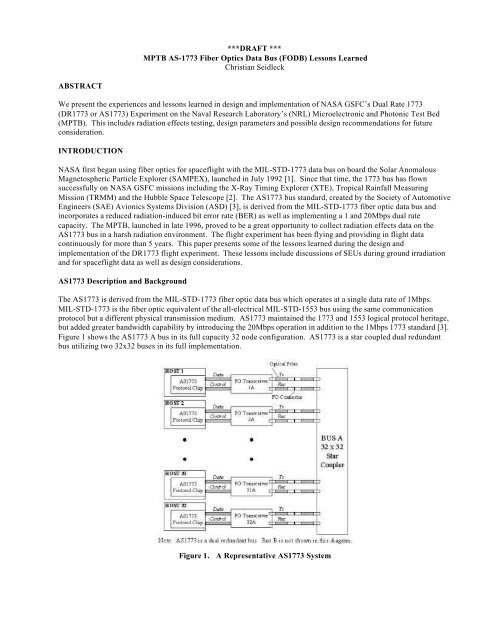
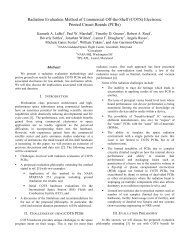
Figure 1 shows the <strong>AS</strong><strong>1773</strong> A bus in its full capacity 32 node configuration. <strong>AS</strong><strong>1773</strong> is a star coupled dual redundant<br />
bus utilizing two 32x32 buses in its full implementation.<br />
Figure 1. A Representative <strong>AS</strong><strong>1773</strong> System
Original <strong>1773</strong> transceivers (with Si photodiodes) were sensitive to direct ionization from protons meaning they would<br />
exhibit a high BER in space applications. For this reason, the use of <strong>1773</strong> protocol fault-tolerant message retries was<br />
implemented in the DR<strong>1773</strong>. Although this allowed for successful use of <strong>1773</strong> in multiple N<strong>AS</strong>A missions, it reduced<br />
effective bus b<strong>and</strong>width by ~50%. This may not be acceptable for high data rate systems. Other hardening techniques<br />
were also employed in the DR<strong>1773</strong> including reduced volume of the photodiode, receiver filtering, as well as a TID<br />
hardening process.<br />
DR<strong>1773</strong> Experiment Design<br />
The DR<strong>1773</strong> was designed to simulate an <strong>AS</strong><strong>1773</strong> spacecraft bus. Briefly, the experiment consisted of three sections;<br />
the optical section, device under test (DUT) section, <strong>and</strong> the experiment control section. The experiment control section<br />
is located inside an A1280 Actel field programmable gate array (FPGA) which controls the experiment operation <strong>and</strong><br />
houses the comm<strong>and</strong> <strong>and</strong> telemetry interface to the <strong>MPTB</strong> motherboard. The optical section consists of 100/140um<br />
optical fibers, 8x8 fiber optic star coupler <strong>and</strong> fiber optic terminations. The DUT section consists of two Boeing 1300nm<br />
<strong>AS</strong><strong>1773</strong> transceivers. A more detailed description of the experiment has previously been published in Jackson [4].<br />
The experiment begins with a mode comm<strong>and</strong> from the <strong>MPTB</strong> host processor. Once this comm<strong>and</strong> is received, the<br />
control section will generate a Manchester encoded 32-bit pseudo-r<strong>and</strong>om message. The control section will then select<br />
a DUT transmitter <strong>and</strong> receiver <strong>and</strong> send the message out over the bus. The control section then reads the message back<br />
for comparison. If the return message is different from the generated message then an error counter is incremented. This<br />
process is continued until another mode comm<strong>and</strong> is sent, or the experiment is turned off. A total word counter is<br />
incremented for each message sent over the fiber optic link. This word counter can be used in conjunction with the error<br />
counter for each mode to determine bit error rate information.<br />
The experiment operates at 20Mbps only in one of two defined modes. “ED” mode where transceiver 1 sends messages<br />
to transceiver 2 or “DE” mode which reverses the transmission direction between transceivers. As noted in previous<br />
publications, the physical optical fiber connections for these two links are different. ED uses a physical contact (PC)<br />
polished fiber optic terminal as opposed to DE mode’s flat polished. <strong>Data</strong> presented over the life of this experiment<br />
supports the idea that the PC termini provides a more robust <strong>and</strong> lower loss scheme of optical connection.<br />
Ground Proton Testing<br />
Results from tests performed prior to flight are summarized below in Table 1. Receiver proton testing was performed<br />
with varied optical attenuation using a nominal -17dB, -23 <strong>and</strong> -25dB. Proton incident angle was varied, <strong>and</strong> energies<br />
used were 63Mev degraded to 38.2MeV. For proton total ionizing dose (TID) no degradation was observed at 35 kRads<br />
(Si). No heavy ion testing was performed due to packaging limitations, however, the devices were suspected of heavy<br />
ion sensitivity.<br />
<strong>Data</strong> Rate 1Mbps 20Mbps<br />
Normal Optical No SEUs 1 error total all runs (s <<br />
Attenuation<br />
1.4 E -10 cm 2<br />
Additional Optical<br />
Attenuation<br />
No SEUs @ -23dB See graph<br />
Angular Incidence N/A See graph<br />
Energy Dependence N/A Minimal (10-20%)<br />
Table 1 Boeing DR<strong>1773</strong> Proton SEU Test Results- Receiver
Figure 2 shows the error cross section vs. induced optical attenuation. Figure 3 shows the error cross section vs. beam<br />
incidence angle.<br />
Error Cross section in cm 2<br />
Error Cross Section in cm 2<br />
1.00E-06<br />
1.00E-07<br />
1.00E-08<br />
1.00E-09<br />
1.00E-10<br />
Errors observed<br />
No errors observed<br />
1.00E-11<br />
-30 -25 -20 -15 -10 -5 0<br />
Link Attenuation in dB<br />
Figure 2 Error cross section vs. attenuation 90 degrees incidence<br />
1.00E-06<br />
1.00E-07<br />
1.00E-08<br />
1.00E-09<br />
In-Flight Experiment Results<br />
0 20 40 60 80 100 120<br />
Angle<br />
-27 dB Atten<br />
-23 dB Atten<br />
Figure 3 Receiver error cross section by beam incidence angle<br />
As previously mentioned, the number of errors on each of the two fiber optic links is being captured. Note that these<br />
modes are mutually exclusive (only one link is active at a time). For this reason, results for each of the modes are<br />
presented separately. Figure 4 shows the daily number of errors for mode 1 or “ED” mode over ~5 years of collected<br />
data. This mode uses the PC fiber optic termini <strong>and</strong> has performed robustly with an overall bit error rate BER=2.118E -14<br />
errors/bit.<br />
Figure 5 shows the daily number of errors for mode 2 or “DE” mode for a lesser period of time. This is in part due to the<br />
fact that the experiment was comm<strong>and</strong>ed in DE mode less of the time <strong>and</strong> for shorter periods of time. The data shows<br />
this mode, which utilizes the flat connection termini has a much higher susceptibility to errors. A BER of 6.609E -11<br />
errors/bit was calculated for the time spent in this mode. Table 2 summarizes the breakdown of BER per year by mode.
Number of Upsets<br />
2.5<br />
2<br />
1.5<br />
1<br />
0.5<br />
0<br />
334<br />
39<br />
80<br />
121<br />
197<br />
238<br />
279<br />
320<br />
361<br />
37<br />
148<br />
233<br />
289<br />
1<br />
91<br />
Julian Day of Year<br />
1997 1998 1999 2000 2001 2002<br />
Figure 4 <strong>MPTB</strong> Transceiver Errors ED Mode 1997-2002 Orbits 0036-3321<br />
Number of Upsets<br />
400<br />
350<br />
300<br />
250<br />
200<br />
150<br />
100<br />
50<br />
0<br />
157<br />
170<br />
183<br />
Upsets<br />
Upset Average = 103.667<br />
52<br />
73<br />
86<br />
114<br />
142<br />
189<br />
218<br />
Julian Day of Year<br />
1998 1999 2000<br />
Figure 5 <strong>MPTB</strong> Transceiver DE Mode 1998-2000 Orbits 0036-3111<br />
260<br />
303<br />
331<br />
Year ED BER DE BER<br />
1997 1.738E -12<br />
1998 4.224E -14<br />
1999 3.855E -14<br />
N/A<br />
3.787E -11<br />
5.303E -11<br />
2000 0 8.501E -11<br />
2001 8.168E -15<br />
N/A<br />
2002 0 N/A<br />
Table 2 ED <strong>and</strong> DE bit error rates by Year<br />
8<br />
34<br />
206<br />
61<br />
300<br />
74<br />
336<br />
133<br />
11<br />
146<br />
52<br />
Average Daily Upsets = 0.0208<br />
159<br />
94<br />
172<br />
135<br />
185<br />
177<br />
198<br />
218<br />
259<br />
259<br />
272<br />
307<br />
285<br />
348<br />
24<br />
70<br />
111
References<br />
[1] M. Flanegan, K. LaBel, “Small Explorer <strong>Data</strong> System MIL-STD-<strong>1773</strong> <strong>Fiber</strong> Optic <strong>Bus</strong>”, N<strong>AS</strong>A Technical Paper 3227,<br />
June 1992.<br />
[2] P.J. Luers, H.L. Culver, J. Plante, “GSFC Cutting Edge Avionics Technologies for Spacecraft”, AIAA Defense <strong>and</strong><br />
Civil Space Programs Conference, Paper 98-5238.<br />
[3] “Interoperability Requirements for <strong>AS</strong><strong>1773</strong>”, AIR-4957 Draft 2.1, May 1996.<br />
[4] G.L. Jackson, K.A. LaBel, C.J. Marshall, J.L. Barth, J. Kolasinski, C.M. Seidleck, P.W. Marshall, “Preliminary Flight<br />
Results of the Microelectronics <strong>and</strong> Photonic Test Bed (<strong>MPTB</strong>) N<strong>AS</strong>A Dual Rate <strong>1773</strong> (DR<strong>1773</strong>) fiber Optic <strong>Data</strong><br />
<strong>Bus</strong>”, GOMAC Conference, 1997.


![mil-std-2223 [test methods for insulated electric wire] - NEPP](https://img.yumpu.com/4036001/1/190x249/mil-std-2223-test-methods-for-insulated-electric-wire-nepp.jpg?quality=85)