

Corrosion of Silver-Plated Copper Conductors - NEPP
Corrosion of Silver-Plated Copper Conductors - NEPP
Corrosion of Silver-Plated Copper Conductors - NEPP

Create successful ePaper yourself
Turn your PDF publications into a flip-book with our unique Google optimized e-Paper software.
B.D. Dunn, A. de Rooij & D.S. Collins<br />
Product Assurance Division, ESA Technical Directorate, ESTEC, Noordwijk, The Netherlands<br />
<strong>Corrosion</strong> <strong>of</strong> <strong>Silver</strong>-<strong>Plated</strong> <strong>Copper</strong> <strong>Conductors</strong><br />
Abstract <strong>Silver</strong>-plated conductors, insulated, with fluorcarbon plastics or aromatic polymide<br />
resin and used in aerospace applications, in both Europe and the United States, have<br />
been examined for evidence <strong>of</strong> red-plague corrosion. Extensive metallurgical<br />
investigations have shown that, in the worst cases, 3% <strong>of</strong> the strands making up<br />
the braid cross-section can have some degree <strong>of</strong> corrosion. Metallography revealed<br />
that it had initiated at isolated defects in the silver-plating.<br />
A test method has been developed suitable for the acceptance testing <strong>of</strong> fabricated<br />
wires and cables. Its use has shown that the extent <strong>of</strong> corrosion is only marginally<br />
affected by the type <strong>of</strong> insulation, strand manufacturer, and wire and cable processors.<br />
Plating type and thickness and also the position <strong>of</strong> the strands in the cable do<br />
influence their corrosion behaviour.<br />
The mechanisms <strong>of</strong> red-plague corrosion and the influence <strong>of</strong> such parameters as<br />
halides and moisture are discussed and recommendations made for its preclusion.<br />
Résumé Des conducteurs à revêtement argent, isolés au plastique fluorocarboné ou à la résine<br />
polyimide et destinés à l'usage spatial, aussi bien en Europe qu'aux Etats-Unis, ont été<br />
examinés pour y déceler les traces éventuelles de corrosion due à la 'peste rouge'. Des<br />
études métallurgiques poussées ont montré que, dans les cas les plus défavorables 3%<br />
des fils sur l'épaisseur de la tresse peuvent présenter certain degré de corrosion.<br />
L'étude métallographique a révélé que cette érosion prend son origine dans des<br />
défauts localisés dans le revêtement argent.<br />
On a mis au point une méthode d'essai qui convient aux essais de recette des fils<br />
et câbles. Son utilisation a montré que le degré de corrosion n'est affecté que de<br />
façon marginale par le type d'isolation, par la provenance des fils et les conditions<br />
d'élaboration des fils et câbles. Le type de revêtement son épaisseur ainsi que la<br />
position des fils à l'intérieur du cable influencent également la tenue à la corrosion.<br />
On étudie les mécanismes de cette corrosion ainsi que les facteurs tels que la<br />
présence des halogènes et l'humidité, et on présente des recommandations en vue<br />
d'éviter une telle corrosion.<br />
ESA Journal 1984, Vol. 8 307
308<br />
Introduction <strong>Silver</strong>-plated conductors are generally specified when wires and cables must have a good<br />
resistance to high temperature. They are invariably insulated with fluorocarbon plastics or<br />
aromatic polymide resin, which have high working temperatures and low out-gassing<br />
properties under vacuum. These wire and cable materials are those most commonly<br />
selected for use in ESA's satellite and manned spacecraft projects. <strong>Silver</strong>-plated copper<br />
wire is also used extensively for military and aerospace applications in both Europe and the<br />
United States.<br />
The purpose <strong>of</strong> this paper is to detail the findings <strong>of</strong> the metallurgical examinations<br />
performed by ESA on cables discovered to have degraded by red plague corrosion. In<br />
addition, an extensive laboratory test programme was undertaken in an attempt to gain a<br />
more comprehensive understanding <strong>of</strong> the red plague phenomenon. The aims <strong>of</strong> this<br />
programme will be discussed, as will the results achieved to date. A test method based on<br />
the laboratory procedures <strong>of</strong> Anthony & Brown 1 has been developed into a draft ESA<br />
specification, which is thought suitable for the acceptance-testing <strong>of</strong> fabricated wires and<br />
cables.<br />
Papers published in the literature 1-6 on red plague are limited to the 1965 – 70 period and<br />
no more recent articles have appeared. This paper will initially reiterate the current<br />
theories related to the mechanism <strong>of</strong> red-plague corrosion and, as a historical record, will<br />
include an account <strong>of</strong> the reasons for the selection <strong>of</strong> silver plated conductors for ESA<br />
projects.<br />
Previous studies <strong>of</strong> redplague<br />
corrosion Two potential corrosion problems were recognised to be associated with the use <strong>of</strong><br />
silver-plated copper conductors in the 1960s. Because <strong>of</strong> their characteristic corrosion<br />
products, they are referred to throughout the electronics industry as 'red-plague' and<br />
'green plague'. Red plague is the cuprous-oxide (possibly with some black cupric oxide)<br />
corrosion product that forms when a galvanic cell is formed between copper and silver.<br />
Green plague is the reaction product <strong>of</strong> some resin-based solder fluxes with copper<br />
oxide; it has been found on tin- and silver-plated conductors and is considered to be an<br />
undesirable cosmetic defect.<br />
A number <strong>of</strong> reports 1-6 were written in the late sixties which established that red plague<br />
originates at breaks in the silver plating <strong>of</strong> copper-wire strands in the presence <strong>of</strong><br />
moisture and oxygen. Although some authors considered the problem to be persistent,<br />
uncontrolled and unsolved, others presented solutions thought likely to avoid the<br />
problem. A NEMA investigation reported 6 that out <strong>of</strong> a total US production <strong>of</strong> 18 to 20 x<br />
10 9 ft <strong>of</strong> silver-plated copper wire, only 10 5 ft (i.e. 0.003%) had a significant amount <strong>of</strong><br />
red plague and that no malfunctions could be attributed to this phenomenon.<br />
Several investigative activities were undertaken by ESA in the mid-seventies. These<br />
included laboratory evaluations, a European red-plague survey, and eventually the<br />
auditing <strong>of</strong> wire manufacturers' premises. It was concluded that silver-plated copper<br />
conductors would be suitable for general spacecraft usage, but essential that the platings<br />
be defect-free and <strong>of</strong> uniform thickness (at least 2μm, and preferably 4μm). It was<br />
considered that red plague could be avoided if the wire manufacturer and the user<br />
companies implemented certain mandatory controls. Also, extreme gauge sizes <strong>of</strong><br />
stranded copper, such as large gauge AWG '0' and ‘4’, should be nickel-plated copper,<br />
and very thin gauge AWG '26' and smaller must use high-strength copper alloy strands<br />
with a silver-plated finish. ESA and its contractors have experienced no practical<br />
problems during wire interconnection (e.g. soldering, crimping and wire wrapping),<br />
hardware integration or service operation with silver-plated wire cables and harnesses.<br />
The results <strong>of</strong> studies 1-5 performed in the 1960s can be summarised as follows:<br />
(i) Imperfections ranging from porosity to deep scrapes penetrate the silver<br />
plating and reveal the copper core <strong>of</strong> a wire strand. Such damage may result<br />
from the use <strong>of</strong> defective wire-drawing dies, wear action between strands<br />
during stranding and braiding operations or when conductor strands are<br />
wound and re-wound from reels to bobbins.<br />
ESA Journal 1984, Vol. 8
(ii) Moisture may penetrate beneath the insulation <strong>of</strong> wires and cables either during<br />
the wire fabrication process, during insulation testing or from the humidity in<br />
air.<br />
(iii) The presence <strong>of</strong> moisture in the region <strong>of</strong> exposed copper can produce an<br />
electrolytic cell, the copper tending to corrode and protect its more noble<br />
silver plating. The following reactions were proposed:<br />
At the anode (i.e. exposed copper):<br />
4Cu + 4OH - = 2Cu2O + 2H 2 O + 4e -<br />
At the cathode (i.e. silver<br />
plating):<br />
O2 + 4H + + 4e- = 2H2O<br />
The sum reaction is:<br />
4Cu + O2 + 4H + + 4OH = 2CU2O + 4H2O<br />
Note that the water is not consumed and in the presence <strong>of</strong> oxygen the galvanic<br />
copper corrosion can proceed indefinitely.<br />
(iv) <strong>Copper</strong> hydroxides are soluble in water and will contaminate the water that<br />
surrounds the stranded wires. As the water dries out, the cuprous-oxide crystals,<br />
which have a characteristic red appearance, precipitate out onto the silver<br />
plating.<br />
(v) Excessive corrosion can impair the wire's fatigue life and electrical<br />
conductivity.<br />
There is no wire conductor material that can be recommended as the panacea to Historical basis for selecting<br />
all potential corrosion, processing and application problems. The suitability <strong>of</strong> silver-plated copper<br />
various metallic finishes on copper wires for spacecraft applications was studied by conductors<br />
ESA in 1975. The choice was finally limited to tin, silver and nickel. However, due<br />
to. its low melting point, tin could not be considered for the insulation materials that<br />
require high-temperature processing, such as PTFE, FEP, Teflon, Tefzel and Kapton.<br />
A review <strong>of</strong> the literature, discussions with cable specialists and the results <strong>of</strong> ESA<br />
metallurgical test programmes indicated many advantages and disadvantages when<br />
choosing silver or nickel finishes.<br />
<strong>Silver</strong> finishes (more than 2mm thick)<br />
Advantages<br />
a. Exceptional electrical conductivity (essential for certain RF applications), so that<br />
smaller conductors may be employed than if nickel plated (i.e. possible weight<br />
saving).<br />
b. Good resistance to high temperature (200°C).<br />
c. Excellent solderability whether new or after many years' exposure to<br />
uncontrolled environments.<br />
d. Excellent crimpability and suitable for wire wrapping without cracking.<br />
e. Experience with this wire finish is very good in Europe and the USA (confirmed<br />
by spacecraft contractors).<br />
f. Least losses from skin effects for RF transmissions.<br />
Disadvantages<br />
a. Poor plating and ingress <strong>of</strong> water into the wires causes a potential red-plague<br />
hazard.<br />
b. The silver surface may react with substances such as glycol to produce a potential<br />
flammability hazard (recent studies have also shown this reaction to occur with<br />
nickel and tin conductors).<br />
c. Slightly higher cost than other coatings.<br />
d. The larger gauge wires (AWG '0' and ‘4’) cannot be used with this finish as cold<br />
welding at points <strong>of</strong> contact between the wire strands may increase wire rigidity.<br />
ESA Journal 1984, Vol. 8<br />
309
310<br />
Nickel finishes<br />
Advantages<br />
a. No known potential conductor corrosion risks.<br />
b. Very high temperature rating (260°C).<br />
c. Minimal storage controls needed.<br />
d. Good flexibility after long-term aging at 200°C.<br />
Disadvantages<br />
a. Impossible to solder with the non-activated fluxes prescribed by ESA 9 . With<br />
activated fluxes, it has a variable solderability, dependent on the type <strong>of</strong> nickel<br />
plating and thickness <strong>of</strong> nickel oxide. Active fluxes are undesirable for soldering<br />
hook-up wires as they are drawn under the insulation by capillary action <strong>of</strong> the<br />
strands and can cause corrosion, outgassing and corona problems under vacuum.<br />
b. Crimpability is fairly good, but more frequent adjustments have to be made to the<br />
crimping tool than with other finishes. Contact resistance is affected by the<br />
cleanliness <strong>of</strong> the surface. Ohmic resistance may be erratic for nickel platings<br />
(silver-plated copper connections exhibit negligible ohmic variations between<br />
similar joints).<br />
c. Nickel-plated conductors exhibit 7% to 10%. more DC resistance with<br />
substantially greater power (I 2 R) loss.<br />
d. Nickel has an unsuitable magnetic moment for certain spacecraft experiments.<br />
Reliability<br />
In assessing the reliability <strong>of</strong> a spacecraft system it is necessary to take into<br />
account individual materials, processes and their failure modes under various<br />
environmental conditions. In reviewing the above advantages and disadvantages <strong>of</strong><br />
silver and nickel platings much emphasis was attributed to the red-plague question.<br />
From a total <strong>of</strong> nineteen replies to the ESA survey in 1975 <strong>of</strong> European aerospace<br />
users <strong>of</strong> silver-plated wires, only one company had experienced a problem (no details<br />
given), six companies had 'minor problems', but all before 1965 and none since.<br />
Eleven companies had never encountered problems, including one using 400 km <strong>of</strong><br />
silver-plated cable per year.<br />
These investigations showed that no functional failure had been reported under<br />
operational conditions. Consequently, the selection <strong>of</strong> wire and cable materials would<br />
have to be based on controlled processing and well-defined application<br />
considerations. A similar survey performed by NEMA 6 supported the ESA findings.<br />
Processing precautions<br />
To minimise the occurrence <strong>of</strong> red plague, ESA has instigated a number <strong>of</strong><br />
requirements via specification SLP/2110:<br />
a. Prior to silver plating, conductors shall be cleaned with a reverse current in an<br />
alkaline bath.<br />
b. To avoid scratches, all drawing and stranding dies shall be exchanged regularly and<br />
whenever necessary.<br />
c. Drawing, stranding and braiding <strong>of</strong> silver-plated copper wire and shields shall not<br />
be performed with the same dies and tools used for processing tin, nickel, or<br />
other plated conductors.<br />
d. No lubricants shall be used during stranding or braiding.<br />
e. Water quenching shall not be used in the production process.<br />
f. Hygroscopic cleaning agents shall not be applied in production or during testing<br />
(no water-tank testing).<br />
g. Strands, wires and cables shall be sealed such that the humidity environment for<br />
storage and shipment is less than 50% relative humidity.<br />
h. All open wire ends shall be sealed against water ingress.<br />
i. <strong>Silver</strong>-plating thickness <strong>of</strong> at least 2 μm (80 μinch) is required for all strand<br />
sizes.<br />
j. <strong>Silver</strong> plating shall be uniform and concentric around the copper strand so<br />
ESA Journal 1984, Vol. 8
that no area is covered with less than 1.5μm as determined by microsectioning.<br />
k. <strong>Silver</strong> plating shall be free from porosity.<br />
In the latter half <strong>of</strong> 1983, ESA experienced the first case <strong>of</strong> red plague identified<br />
on a short length <strong>of</strong> 125Ω RF cable withdrawn from a contractor's store. On<br />
stripping the outer insulation, severe corrosion was noted to be present in small<br />
irregular patches along the newly exposed braid. To assess the origin and extent <strong>of</strong><br />
this problem, and to define remedial actions, extensive efforts were made to locate<br />
and inspect all silver-plated copper wires and cables purchased and stored by ESA<br />
contractors from the same cable manufacturer. Finally, new wires and the<br />
remainders <strong>of</strong> wires and cables on reels from various silver-plated wire/cable<br />
suppliers were inspected by project contractors.<br />
The following is a summary <strong>of</strong> the metallurgical examinations performed on the<br />
three cables noted to have suffered from red-plague corrosion. Extensive stripping<br />
operations have only revealed corrosion, in irregular patches, along the newly<br />
exposed lengths <strong>of</strong>' braided shield. Insulation stripping has not revealed any<br />
corrosion damage to the inner wire conductors. The most severe attack was seen on<br />
the 125Ω RF cable, manufactured in 1978 (Inner conductors are 2μm silver-plated<br />
copper strands with insulation constructed <strong>of</strong> helically wound and sintered PTFE<br />
tape: the braiding is closely woven single copper braid <strong>of</strong> AWG '36' having a<br />
silver-plating <strong>of</strong> 2 the outer jacket is extruded FEP, black in colour). Figures 1 - 5<br />
relate to the most severely attacked cable.<br />
Experimental procedure<br />
Visual inspection<br />
The conductors and braided shields <strong>of</strong> the submitted cables were inspected with a<br />
stereo microscope under x20 magnification, the various insulations being removed<br />
with a scalpel blade before inspection. 6% <strong>of</strong> the 125 Ω cable produced in 1978 has<br />
been visually inspected by ESA, cables users and cable suppliers.<br />
SEM inspection<br />
Corroded strands <strong>of</strong> braiding were cut from the cable and examined by scanning<br />
electron microscopy and X-ray spectrometry (EDAX).<br />
Auger Analysis<br />
The surface <strong>of</strong> the silver-plated areas was sputter-removed with an argon beam<br />
and the sub-surfaces reanalysed to assess the penetration <strong>of</strong> any surface<br />
contamination. Auger analysis was also applied to the ends <strong>of</strong> corroded and<br />
fractured strands.<br />
Metallography<br />
The cables and individual strands were mounted into a cold-setting plastic and<br />
micro-sectioned. The mounts were ground and polished to a 0.5μm diamond finish<br />
and examined both as-polished and etched. Polarised light could distinguish reel<br />
cuprous oxide (Cu2O) from black cupric oxide (CuO).<br />
Summary <strong>of</strong> findings<br />
No cracks or pinholes were observed in the outer jacket insulation materials.<br />
After removal <strong>of</strong> the outer jackets, many local areas <strong>of</strong> discolouration could be<br />
seen on the silver strands; they had a red, black and green-blue appearance. Several<br />
individual strands were noted to have shattered in a brittle manner (Figs. 1 & 2).<br />
Examination <strong>of</strong> corroded<br />
cables withdrawn from<br />
storage<br />
Visual inspection <strong>of</strong> the 125 Ω, 1978 cable identified the corrosion areas to have<br />
various sizes and an irregular distribution over the inspected cable lengths (no in Figure 1. Appearance <strong>of</strong> the most severely<br />
depth inspections were made <strong>of</strong> the other cables as they were not integrated into corroded braid after approximately 5<br />
years <strong>of</strong> storage. Despite the presence <strong>of</strong><br />
flight hardware).<br />
many corrosion sites (circled in a), the<br />
braid is still mechanically intact and can<br />
be spread out (as in b)<br />
ESA Journal 1984, Vol. 8 311
Figure 2. Colour photomicrographs <strong>of</strong><br />
typical 'red-plague' corrosion areas on<br />
braiding, as circled in Figure 1.<br />
a. Red and green corrosion products<br />
associated with two strands that have<br />
completely broken; the brittle fracture<br />
surfaces are arrowed ( x 100);<br />
b. <strong>Corrosion</strong> products are black (1), red<br />
(2) and green-blue (3)<br />
Figure 3. Scanning electron photomicrographs<br />
<strong>of</strong> fractured ends <strong>of</strong> strands from braid shown<br />
in Figure 2a. The Cu20 phases are<br />
characteristically seen as ruby-red crystals<br />
under crossed polar light. CuO appears black<br />
under the same conditions<br />
312<br />
Examination <strong>of</strong> the corroded strands in the SEM showed them to consist entirely <strong>of</strong><br />
brittle oxidised copper crystals. Adjacent strands supported crystals <strong>of</strong> cuprous oxide<br />
which were adherent to the silver platings (Fig. 3). Only the presence <strong>of</strong> copper, silver<br />
and a trace <strong>of</strong> chlorine were detected by EDAX analysis <strong>of</strong> the strand surfaces.<br />
Auger examination revealed that both the silver surfaces, and the copper-oxide<br />
films were contaminated by chlorine and fluorine to a maximum <strong>of</strong> 5 at%. Depth<br />
pr<strong>of</strong>iles revealed fluorine in t lie silver plating to a depth <strong>of</strong> 40 Å. Further Auger<br />
analyses also detected the presence <strong>of</strong> chlorine and fluorine at the central area <strong>of</strong> the<br />
strand fracture surface. 1 his area was composed entirely <strong>of</strong> copper-oxide crystals<br />
(Fig.4). Both chlorine and fluorine, when present as free ions, would tend to be an<br />
accelerating factor in any galvanic corrosion mechanism.<br />
The micro-sections <strong>of</strong> the corroded 125Ω cable are described in Figures 5-9. Only a<br />
few (approximately 3%) <strong>of</strong> the 143 strands that make up the braid have corroded. The<br />
loose-fitting outer jacket has at some stage retained a liquid that promoted galvanic<br />
corrosion at minute locations <strong>of</strong> damaged silver. The average silver-plating thickness<br />
<strong>of</strong> these strands is 2 – 3μm. <strong>Copper</strong> oxides are present on the outside surfaces <strong>of</strong> silver<br />
strands at locations far from the corrosion sites. This is important as it gives the<br />
impression, from visual inspections, that the amount <strong>of</strong> corrosion and red plague is<br />
more extensive than initially apparent and illustrates that the braid must have been<br />
almost totally immersed in a liquid to enable the transfer <strong>of</strong> copper ions to these<br />
locations. On drying out, tile liquid has precipitated at least three copper compounds:<br />
blue cupric hydroxide (Cu(OH)2), red-coloured cuprous-oxide crystals (Cu20) and<br />
black cupric-oxide layers (CuO), onto the silver surfaces. The red colouration on the<br />
braid is likened to a process <strong>of</strong> bleeding out <strong>of</strong> copper ions from occasionally<br />
corroding fissures. On drying, capillary forces tend to concentrate oxide precipitation<br />
at the braid cross-hatched turns.<br />
ESA Journal 1984, Vol. 8
Extensive insulation stripping, visual inspections and micro-sections have never<br />
revealed the oxidation or corrosion <strong>of</strong> any internal conductors from spacecraft wires<br />
and cables. These internal conductors, as seen in Figures 6 and 7, are tightly held<br />
within their insulation Jackets.<br />
It is noticeable that the outer jackets are loose-fitting and particularly suitable for the<br />
ingress <strong>of</strong> moisture from unsealed cable ends. The volume <strong>of</strong> air that is contained<br />
within the 125 Ω cable has been derived from the transverse cross-section shown in<br />
Figure 7a.<br />
The cross-sectional areas <strong>of</strong> the cable constituents are:<br />
a. Complete cable 25.5090 mm 2<br />
b. Each filler 1.4878<br />
c. Each inner wire 4.1975<br />
d. Outer insulation 7.3142<br />
c. Individual braid 0.0182<br />
The ‘area <strong>of</strong> voids’ under the outer insulation was calculated by subtraction <strong>of</strong> each<br />
cable constituent from the total cable cross-sectional area, i.e.<br />
Area <strong>of</strong> voids = a – 2b – 2c – d - 144e = 4.2034 mm 2<br />
In other words the amount <strong>of</strong> air retained beneath the Outer cable insulation accounts<br />
for 16.48%) by volume <strong>of</strong> cable, or, each 1m <strong>of</strong> cable contains approximately 4 cm 3 <strong>of</strong><br />
air.<br />
Figure 4. Secondary electron image <strong>of</strong> the<br />
copper-oxide crystals seen at the centre <strong>of</strong><br />
a corroded and fractured strand. The<br />
SEM image is superimposed on the Auger<br />
analysis <strong>of</strong> this area (showing traces <strong>of</strong><br />
chlorine and fluorine associated with<br />
copper oxides)<br />
Figure 5. Detailed metallographic<br />
examination <strong>of</strong> the red-plagued cables. The<br />
most severely corroded cable (shown in a)<br />
was potted and micro-sections made through<br />
the severely corroded braid in the X-X<br />
plane. A second section was made in the Y-Y<br />
plane which is still covered in black FEP<br />
a. Extensive red plague on braid;<br />
b. General construction <strong>of</strong> cable examined<br />
ESA Journal 1984, Vol. 8 313
Figure 6a. Section through X -X (see<br />
Fig. 5), the superimposed numbers<br />
referring to corroded strands. Three <strong>of</strong><br />
the 143 strands are corroded to some<br />
extent (2.1%)<br />
Figure 6b. Detail <strong>of</strong> strand no. 1 from<br />
Figure 6a. Adjacent strands are<br />
uncorroded, but support crystals <strong>of</strong><br />
cuprous oxide (x150)<br />
Figure 6c. One strand in the centre <strong>of</strong> the<br />
braid has been totally transformed to a<br />
silver tube. Cuprous oxide (visible as<br />
bright red under polarised light) is located<br />
within the silver tube and within all the<br />
inter-strand spaces<br />
Figure 6d. Tunnelling corrosion along<br />
strand no. 3 (x 150)<br />
314<br />
Conclusions<br />
These laboratory examinations have confirmed the existence <strong>of</strong> red-plague corrosion,<br />
restricted to isolated areas, on the outer braid shield <strong>of</strong> three spacecraft cables. In the<br />
most severely affected area, 3% <strong>of</strong> the strands making up the braid cross-section have<br />
been affected. It is estimated that a maximum <strong>of</strong> 2% <strong>of</strong> the electrically conductive path<br />
has been degraded.<br />
The silver-plating thickness on the braids is generally good, but corrosion has<br />
initiated at randomly spaced defects. The loose-fitting out jacket facilitates the<br />
ingress <strong>of</strong> humidity and chloride and fluoride contaminants may possibly have an<br />
accelerating effect on the galvanic corrosion mechanism.<br />
The actual extent <strong>of</strong> red-plaque corrosion is markedly less than would be expected<br />
from visual inspection alone. <strong>Corrosion</strong> has only taken place in isolated areas. These<br />
areas contain silver and copper oxides (both <strong>of</strong> which are electrically conductive).<br />
The evidence <strong>of</strong> liquid on the braid suggests that in the past the
plague corrosion on their braided screens. The inner conductors <strong>of</strong> spacecraft cables<br />
and wires have never shown any form <strong>of</strong> corrosive attack.<br />
The probability <strong>of</strong> wire/cable degradation due to copper corrosion <strong>of</strong> insulated<br />
silver-plated copper wire is concluded to be very small in view <strong>of</strong> the survey findings<br />
and the results <strong>of</strong> the laboratory examinations.<br />
ESA Journal 1984, Vol. 8<br />
Figure 7a. Section made through Y-Y (see Fig. 5).<br />
Superimposed are numbers referring to corroded<br />
strands. Four <strong>of</strong> the 143 strands are to some extent<br />
corroded (2.8%) (outer FEP jacket has been peeled<br />
back and appears as two rings)<br />
Figure 7b. One corroded strand is surrounded by<br />
non-corroded adjacent strands covered by cuprousoxide<br />
crystals. Note large air gaps between outer<br />
FEP jacket and inner wire insulants (x 150)<br />
Figures 7c-e. Remaining corroded strands in<br />
section Y-Y (x 150)<br />
315
Figure 8. Section through red crystals on the intact 2 - 3 μm thick<br />
silver coating on strand from corroded braid (x 600)<br />
316<br />
Programme to evaluate<br />
corrosion susceptibility <strong>of</strong><br />
wires and cables<br />
Figure 9. Colour micrograph clearly showing the various copper oxides to<br />
have ‘tunnelled’ beneath the silver coating. They are also present on the<br />
outer surface (x 600)<br />
Objectives<br />
A programme <strong>of</strong> work has been undertaken by ESA with the aim <strong>of</strong> understanding<br />
the phenomenon <strong>of</strong> red plague in greater detail. The basic mechanisms <strong>of</strong> corrosion<br />
presented in the literature have been described above, but a variety <strong>of</strong> factors still need<br />
to be resolved. The objectives <strong>of</strong> the programme include:<br />
a. To establish a database on the red-plague susceptibility <strong>of</strong> wire and cable products<br />
presently being supplied for ESA spacecraft projects.<br />
b. To develop and assess the test method described by Anthony & Brown 1-8 for the<br />
detection <strong>of</strong> susceptible products.<br />
c. To determine the origin and extent <strong>of</strong> contaminants on silver-plated strands –<br />
particularly chlorine and fluorine as were detected on the corroded braid and<br />
reported above. Also to assess their influence on the corrosion mechanism.<br />
d. To assess the quality and suitability <strong>of</strong> virgin silver-plated copper strands,<br />
supplied by two or three producers to the manufacturers <strong>of</strong> insulated wires and<br />
cables.<br />
e. To compare the red-plague susceptibility <strong>of</strong> different wire and cable<br />
manufacturers’ products.<br />
f. To compare the effects <strong>of</strong> different insulation materials.<br />
g. To investigate alternative plated layers.<br />
Several other lines <strong>of</strong> investigation are also being included and the work is still in<br />
progress. Seventy-five different wires and cables (from German, French, Swedish and<br />
US manufacturers and intended for spacecraft use as RF shielded cables, hook-up<br />
wires and coaxial cables) have been evaluated between November 1983 and March<br />
1984, including the individual assessment <strong>of</strong> a total <strong>of</strong> 100 different braids and<br />
internal conductors. All were subjected to accelerated corrosion testing. For cost<br />
reasons, the number <strong>of</strong>' samples forwarded for surface analysis has been restricted to<br />
51.<br />
Laboratory procedures<br />
Visual inspection<br />
The wires and cables were inspected with a binocular microscope under x20<br />
magnification. The outer jacket was removed with a scalpel and the braid<br />
ESA Journal 1984, Vol. 8
inspected. This was repeated for the inner conductors. A polarised-light microscope<br />
was used to establish the presence <strong>of</strong> cuprous oxide (ruby-red under crossed polars).<br />
Areas <strong>of</strong> interest were photographed with a Reichert projection microscope onto<br />
colour film. Post-test inspection results were graded according to criteria listed<br />
below.<br />
Surface analysis<br />
The surfaces <strong>of</strong> conductor strands were analysed by Auger Electron Spectroscopy<br />
(AES) at the Surface Analysis Centre <strong>of</strong> Standard Telecommunication Laboratories<br />
Ltd. This method permits the characterisation <strong>of</strong> surface contaminant levels down to<br />
fractions <strong>of</strong> a mono-layer. AES makes used <strong>of</strong> discrete maxima in the secondary<br />
electron energy spectra obtained from less than a few Angstroms <strong>of</strong> the silver-plated<br />
surface’s thickness during irradiation by X-rays degrade detection <strong>of</strong> these elements<br />
within a few seconds so that spectra must by recorded as soon as the analysis<br />
commences.<br />
Sample strands were always cut and manipulated by means <strong>of</strong> micro-tools and<br />
tweezers. They were mounted onto the AES stage with a minute amount <strong>of</strong> DAG<br />
suspended in pure isopropyl alcohol.<br />
Accelerated test method<br />
All accelerated screening test 8 has been devised based on the work <strong>of</strong> Anthony &<br />
Brown 1 . Essentially two 200mm-long samples are taken from each batch <strong>of</strong> wire or<br />
cable submitted. One length is totally stripped into its constituent materials and<br />
closely inspected for signs <strong>of</strong> contamination or corrosion. 20 mm <strong>of</strong> the insulation is<br />
stripped from one end <strong>of</strong> the second sample, which is inserted into a rubber stopper<br />
fitted to the neck <strong>of</strong> a conical flask containing de-ionised water. The exposed end <strong>of</strong><br />
the sample is positioned 20 mm above the water surface and pure oxygen bubbled<br />
into the water, which is held at 58°C. The test jigs are shown in Figure 10.<br />
ESA Journal 1984, Vol. 8<br />
Figure 10a. Conical-flask set-up for<br />
accelerated corrosion testing <strong>of</strong> RF-shielded<br />
cable to ESA PSS-01 -720 (draft)<br />
Figures 10b & c. Fourteen samples under<br />
test, with flasks held at 58°C in a water<br />
trough (evaporation minimised by particles<br />
<strong>of</strong> floating polystyrene)<br />
317
318<br />
The test environment ensures that the silver-plated conductors <strong>of</strong> the sample are<br />
subjected to a 100% relative humidity, saturated in oxygen, at 58°C. The specified test<br />
duration is 240h (10d), but some duplicate samples were also tested for periods <strong>of</strong><br />
between 90 and 108 h (approximately 4.5 d). At the end <strong>of</strong> the test period the samples<br />
were removed from the flasks and stripped <strong>of</strong> their various insulating layers. The<br />
silver-plated strands were inspected within 3h <strong>of</strong> their removal from the test jig. The<br />
extent <strong>of</strong> corrosion (per 200mm sample) was based on the following visual inspection<br />
criteria:<br />
Code Extent <strong>of</strong> corrosion<br />
0 None<br />
1 One Point, on one or two adjacent strands<br />
2 Slight, on two to eight adjacent strands in one location along sample length<br />
3 Moderate, two to eight adjacent strands in a few locations along sample length<br />
4 Moderate, two to ten adjacent strands in several locations along sample length<br />
5 Severe <strong>Corrosion</strong>, affecting more than 50% <strong>of</strong> the total strands from any conductor in any<br />
one location<br />
Codes 0 to 4 would not be expected to affect the electrical service properties <strong>of</strong> the<br />
wire/cable.<br />
These codes are based on subjective visual inspections. The extent <strong>of</strong> corrosion<br />
was later quantified by means <strong>of</strong> metallographic preparations.<br />
Analysis <strong>of</strong> water from accelerated test<br />
The initial EDAX and AES analyses <strong>of</strong> the corroded braids detected the presence <strong>of</strong><br />
varying amounts <strong>of</strong> chlorine and fluorine on the surface and subsurface <strong>of</strong> those<br />
silver-plated strands. Soluble chloride and fluoride ions might be expected to affect<br />
the rate <strong>of</strong> reaction at any electrochemical corrosion couple. The conditions <strong>of</strong> the<br />
accelerated corrosion test ensure that water, condensed onto the exposed silver<br />
strands, is drawn by capillary attraction into the strand interstices/insulation voids<br />
along the sample length. This water will dissolve soluble ions from the silver surface,<br />
which will migrate down the sample interior and drip back into the conical flask. At<br />
the end <strong>of</strong> the 240 h test period, the flask waters were sent for analysis at the Central<br />
Laboratory <strong>of</strong> the Nederlandse Organisatie voor Toegepast Natuurwetenschappelijk<br />
Onderzoek (TNO).<br />
The fluoride content was determined by an autoanalyser with a fluoride electrode in<br />
the buffered sample solution (accuracy > 5%). The chloride content was determined<br />
using Instrumental Neutron Activation Analysis (INAA). To improve the detection<br />
limit, 3ml <strong>of</strong> the sample solutions were evaporated at 60°C. The remains were<br />
neutron-irradiated for 30min with a neutron flux <strong>of</strong> 10 13 neutrons/cm 2 /s. A Ge(Li)<br />
detector recorded the gamma spectrum, from which the trace elements and their<br />
concentrations could be determined. The conditions for these analyses provided for an<br />
accuracy <strong>of</strong> 5 -10%.<br />
Metallography<br />
The method <strong>of</strong> metallographic preparation followed that described on page 311.<br />
Generally, only single strands were longitudinally sectioned after they had been cut<br />
from the tested wires/cables. Occasionally the entire wire or cable was mounted and<br />
complete transverse sections made across sites <strong>of</strong> corrosion.<br />
Wire- and cable-material variables<br />
a. Conductor strands, copper finished with:<br />
- 2 μm silver, 1 μm silver<br />
- 1 μm nickel with flash <strong>of</strong> silver<br />
- tin<br />
- nickel<br />
ESA Journal 1984, Vol. 8
. Insulation material and application methods:<br />
- FEP melt extruded directly onto wires and cables<br />
- PTFE ram extruded directly onto wires and cables<br />
- Kapton-wrapped tape, sonic with FEP coating sintered to form bond<br />
- Tefzel-ETFE, melt extruded.<br />
Results <strong>of</strong> laboratory investigations<br />
Detailed test reports have been completed for each cable/wire sample submitted<br />
for evaluation, including source, purchase specification, type <strong>of</strong> product and<br />
construction. In some cases the strand suppliers were not known to ESA. Proprietary<br />
information and the individual wire/cable manufacturers' names appearing on<br />
individual test reports (retained by ESA) are not for general release. An example <strong>of</strong><br />
a test report is shown in Figure 11.<br />
ESA Journal 1984, Vol. 8<br />
Figure 11. Typical information contained in a<br />
test report<br />
319
320<br />
Notes: Samples 52 - 75 have not been surface analysed. Nickel + is nominally 2 μm nickel with 0.2 μm flash<br />
<strong>of</strong> silver. Sample 13 * supported silver tarnish, but no corrosion.<br />
ESA Journal 1984, Vol. 8
Visual inspection (as-received)<br />
Each <strong>of</strong> the submitted wires and cables was stripped <strong>of</strong> insulation and the majority<br />
were noted to possess clean, bright silver-plated conductor strands. A wire,<br />
manufactured in 1977, supported very slightly tarnished spots. The surface <strong>of</strong> one<br />
recently supplied cable screen had a straw-coloured appearance and was thought to<br />
have been treated with a corrosion inhibitor.<br />
Surface analyses<br />
A series <strong>of</strong> 51 wire/cable specimens have been subjected to surface analysis. The<br />
results <strong>of</strong> the as-received conductors for the elements chlorine, fluorine, copper,<br />
carbon and silver are presented in Table 1. As will be noted from Figure 11, sulphur<br />
and oxygen were also recorded on the individual test reports, but are not included in<br />
Table 1 as they are not considered to play an active part in the red-plague corrosion<br />
mechanism. The surface analyses made after the corrosion testing are also not<br />
included as those results indicated that both chlorine and fluorine had been mobile<br />
during the test and after drying-out <strong>of</strong> the test samples each had been redistributed.<br />
The results <strong>of</strong> AES differed considerably from corrosion site to corrosion site. Large<br />
atomic percentages <strong>of</strong> copper and oxygen were identified as can be expected from the<br />
<strong>of</strong>ten thick layers <strong>of</strong> red cuprous oxide found adherent to such areas.<br />
The results <strong>of</strong> the surface analyses are summarised in Tables 1 - 6.<br />
* Samples were taken from outside (exposed to factory storage environment) and internal turns <strong>of</strong> bobbins.<br />
The surface- analysis results are averages for each manufacturer.<br />
** Manufacturers-A and -B produced 2 μm-thick silver plating on strands; Manufacturer-C produced<br />
1 μm-thick silver-plating on strands.<br />
The high levels <strong>of</strong> carbon observed on all samples in Table 2 are assumed to have<br />
been picked-up during strand fabrication from the lubricating organic oils utilised in<br />
drawing-down, annealing, and quenching operations on the plated copper strands.<br />
Measurable chlorine levels were found on the strand surfaces from Manufacturers A<br />
and B. Some traces <strong>of</strong> fluorine were also recorded. The source <strong>of</strong> these halides has not<br />
been determined, but such elements are known to be present at concentrations <strong>of</strong> ppm<br />
in the fluids employed during strand manufacture.<br />
Table 3. Auger surface analysis <strong>of</strong> strands after processing into insulated wires and cables (atomic %,<br />
per element)<br />
Comparison <strong>of</strong> the results listed in Table 3 shows that, after application <strong>of</strong> insulation,<br />
there are no striking differences between the products <strong>of</strong> strand manufacturers A and<br />
B.<br />
ESA Journal 1984, Vol. 8 321
322<br />
Table 4. Auger surface analysis <strong>of</strong> strands processed by different manufacturers (atomic %, per<br />
element)<br />
It was thought that the high-temperature processing operations applied to the<br />
various types <strong>of</strong> insulation materials might cause them to partially decompose,<br />
releasing monomers and carbon-oxyfluoride compounds as they were being applied to<br />
stranded wires and braid. The average surface halide analyses are given in Table 5.<br />
Only the kapton tape shows a significant difference, less fluoride being absorbed on<br />
the silver surfaces than from the other insulants. The kapton has a very thin FEP film<br />
which is sintered at a lower temperature than the melt extruded FEP insulations, and<br />
this may account for the lower fluorine levels.<br />
Table 5. Halide concentrations (Auger analysis, atomic %) on silver conductors having various<br />
insulation materials<br />
It was considered that the wire stranding and cable braiding operations might effect<br />
a change in contamination level. Superimposed on this would be the adsorption <strong>of</strong><br />
halogens to the silver strand surfaces from the insulation applied. Table 6 compares<br />
the average surface contamination levels found on unprocessed strand material with<br />
those <strong>of</strong> processed braid and wire.<br />
Table 6. Comparison <strong>of</strong> Auger surface analyses (atomic %) on new strands and strands processed into<br />
wire and cable<br />
It may be deduced from these various sets <strong>of</strong> results that the different manufacturing<br />
operations for processing individual silver-plated strands into finished wires or cables<br />
do modify the chemical structure <strong>of</strong> the strand surfaces. There is a marked increase in<br />
fluorine content, presumably absorbed during the high-temperature application <strong>of</strong><br />
fluorocarbon insulation material to the strands.<br />
ESA Journal 1984, Vol. 8
Extrusion and sintering take place in a temperature region <strong>of</strong> 300-400°C. The<br />
increase in copper content can result from the mechanical damage <strong>of</strong> the outer silver<br />
coating during stranding and braiding, and by diffusion <strong>of</strong> copper into the thin silver<br />
layer during the high- temperature processes. The fall-<strong>of</strong>f in carbon might be due to<br />
the removal <strong>of</strong> lubrication films as they are expelled by the high temperature<br />
processing. Little difference is seen between the average contamination levels <strong>of</strong> braid<br />
and wire strands.<br />
Synthesis <strong>of</strong> accelerated corrosion test results<br />
The results for the wires and cables tested to the Anthony & Brown procedure 1-8<br />
have been presented in Table 1. They are also presented here in the form <strong>of</strong> bar charts<br />
to facilitate interpretation.<br />
The influences Of Surface elements on the corrosion ratings <strong>of</strong> wires and cables are<br />
shown in Figures 12a-g. This graphical presentation highlights two unexpected<br />
findings:<br />
- High amounts <strong>of</strong> C1 - are present with corrosion ratings <strong>of</strong> 0 and 4, whereas<br />
the intermediate ratings are connected to low amounts <strong>of</strong> C1 -<br />
- F - apparently does not contribute to strong corrosion.<br />
ESA Journal 1984, Vol. 8<br />
Figure 12a g. Influence <strong>of</strong> individual<br />
contaminants on the corrosion rating<br />
323
Figure 13. Influence <strong>of</strong> insulation material<br />
on corrosion rating <strong>of</strong> silver-plated strands<br />
Figure 14. Strand manufacturer and<br />
corrosion rating for silver-plated strands<br />
Figure 15. Wire and cable processor and<br />
corrosion rating for silver-plated strands<br />
Figure 16. Positions <strong>of</strong> strand in cable and<br />
corrosion rating (for silver-plated strands).<br />
'Insulated wire' includes inner conductor <strong>of</strong><br />
cables and hook-up wires<br />
324<br />
A possible explanation is thought to be that chlorine and fluorine have different<br />
influences on the metals present.<br />
The influence <strong>of</strong> the various types <strong>of</strong> insulation on the corrosion rating <strong>of</strong> wires and<br />
cables is illustrated in Figure 13. It appears that the high corrosion ratings (at least<br />
rating 4) are achievable in the test irrespective <strong>of</strong> the types <strong>of</strong> insulation used on the<br />
strands. FEP was mainly used as the loose-fitting outer jacket material on RF cables,<br />
and PTFE was mainly used as insulation material on inner conductors. PTFE had<br />
been sintered onto the strands and trapped only a minimal amount <strong>of</strong> air.<br />
The influence <strong>of</strong> the strand manufacturer on corrosion rating is illustrated in<br />
Figure 14. These results show no marked difference (average <strong>of</strong> A = 2.1, <strong>of</strong> B = 1.3).<br />
The influence <strong>of</strong> the wire and cable manufacturer on the corrosion ratings are<br />
illustrated in Figure 15. These results show that the accelerated test will produce<br />
corrosion on wires and cables from all manufacturers.<br />
The influence <strong>of</strong> strand position - whether braid or stranded wire - is illustrated in<br />
Figure 16. It seems that the accelerated test is likely to produce slightly more<br />
corrosion on the braided strands than on the inner conductor. The amount <strong>of</strong> air<br />
trapped within the insulations depends on both the construction <strong>of</strong> the cable and the<br />
method by which the insulation is applied. The braids are surrounded by a far greater<br />
volume <strong>of</strong> air than the inner conductors, thus permitting the ingress <strong>of</strong> greater<br />
quantities <strong>of</strong> oxygen and moisture during the test exposure.<br />
ESA Journal 1984, Vol. 8
Additional observations from accelerated testing are that:<br />
- Samples exposed to the test environment for 10d have only a slightly higher<br />
corrosion rating than the 4.5d samples (from visual inspection only).<br />
- Wire strands finished with either pure tin or pure nickel exhibit no form <strong>of</strong><br />
corrosion from this test environment.<br />
- Wire strands finished with 'nickel plus' (nickel with a 0.2 μm silver flash)<br />
show only slight corrosion in isolated spots, i.e. to a maximum <strong>of</strong> code 2.<br />
<strong>Corrosion</strong> only occurred under cracks in the nickel plating.<br />
- Strands finished with 1 μm <strong>of</strong> silver tend to corrode more rapidly than those<br />
with a nominal 2 μm finish.<br />
- When corrosion does occur in the strands <strong>of</strong> a wire or cable, it is usual that<br />
the end exposed within the flask supports a black corrosion product, while<br />
the centre part <strong>of</strong> the sample corrodes more extensively and is covered<br />
predominantly in red corrosion products.<br />
Results <strong>of</strong> water analyses from accelerated tests<br />
The halide contents <strong>of</strong>' the water contained within the conical flasks during the 10d<br />
tests were noted to increase. The analytical results have been compared against the<br />
corrosion ratings for the wires or cables in Figures 17ab.<br />
These figures show that contaminated water from the wire ends is returned to the<br />
flask in the form <strong>of</strong> drips. This confirms that the halides determined by AES existed<br />
in an ionic form rather than as monomers or polymers. There is a certain<br />
resemblance between Figures 17a,b and 12a,b.<br />
Metallographic findings and case studies<br />
The results and discussions have so far concentrated on the subjective visual<br />
appearance <strong>of</strong> red-plague corrosion products adhering to the accelerated<br />
corrosion-test samples. It will be noted that single isolated defects in the silver-plated<br />
layer <strong>of</strong> copper strands can initiate galvanic corrosion. In the presence <strong>of</strong><br />
water, the corrosion products may be dispersed over a wide surface area and, on<br />
drying-out, precipitate in the form <strong>of</strong> red and black crystals (Cu2O and CuO). This<br />
process renders inspection and quantitative evaluation <strong>of</strong> the extent <strong>of</strong> corrosion<br />
extremely difficult.<br />
A very important and complimentary aspect <strong>of</strong> the accelerated corrosion test<br />
programme has been the metallographic work. It was frequently found that microsections<br />
made transversely through wire strands that supported red plague failed to<br />
locate any corrosion <strong>of</strong> the copper core - only crystals <strong>of</strong> copper oxides were seen<br />
adhering to the outer silver surface. It therefore became standard laboratory practice<br />
to cut short lengths <strong>of</strong> red-covered strands from different corrosion sites on any one<br />
braid or stranded conductor. These lengths were distributed on the bottom <strong>of</strong> a mould<br />
then mounted and longitudinally sectioned. Often only one or two strands from the<br />
few dozen in the mount were noted to have actually corroded, and these sections were<br />
then photo- rnicrographed. Display <strong>of</strong> corrosion points selected in this manner can<br />
give an unduly pessimistic impression <strong>of</strong>' the real extent <strong>of</strong>' corrosion that exists in<br />
the total cross-section <strong>of</strong> conductor strands.<br />
Four 'worst cases' are shown in Figures 18 - 21 to illustrate the metallographic<br />
findings.<br />
ESA Journal 1984, Vol. 8<br />
Figure 17a-b. Comparison <strong>of</strong> halide additions to<br />
water from test samples with their corrosion<br />
ratings<br />
325
Figure 18. Transverse and longitudinal sections<br />
through red-plague corrosion site on sample no.<br />
16. The braid consists <strong>of</strong> 144 strands, <strong>of</strong> which<br />
only two-support copper corrosion. All strands are<br />
<strong>of</strong> 2 m m silver-plated copper. The insulation<br />
materials are black FEP for the outer jacket and<br />
natural PTFE on the inner conductors. The<br />
longitudinal sections show that galvanic corrosion<br />
has initiated at local breaks in the silver plate<br />
(after 10d <strong>of</strong> accelerated corrosion testing).<br />
326<br />
a. Outer braid sectioned across site <strong>of</strong> worst<br />
corrosion. Note braid has 144 strands, two<br />
<strong>of</strong> which show signs <strong>of</strong> internal corrosion<br />
b. Transverse section through worst<br />
corrosion site (x 800)<br />
c. Longitudinal section through worst<br />
corrosion site (x 600)<br />
ESA Journal 1984, Vol. 8
Figure 19. Transverse and longitudinal sections<br />
through red-plague corrosion site on sample no.<br />
34. All strands are <strong>of</strong> 2 μm silver-plated copper.<br />
The insulation material is Tefzel-ETFE. In any<br />
transverse plane only one strand is noted to he<br />
corroded, initiation progressing from local<br />
defects in the Aver plating (after 10 d <strong>of</strong><br />
accelerated corrosion testing).<br />
a. Extensive red corrosion on adjacent strands<br />
(x 60);<br />
b. Transverse section in most corroded area<br />
(x120);<br />
c. Longitudinal section through severely<br />
corroded area (x 600);<br />
d. Transverse section in most corroded area (x<br />
600)<br />
ESA Journal 1984, Vol. 9 327
Figure 20. Longitudinal sections showing the most<br />
severely corroded strands (some oxidised<br />
throughout their section) from sample no. 9. Slight<br />
subsurface exists oil on one strand <strong>of</strong> the inner<br />
conductor, after 10d <strong>of</strong> accelerated corrosion<br />
testing. All strands are <strong>of</strong> 1 m m silver-plated<br />
328<br />
copper. The insulation materials are natural FEP<br />
for the outer jacket and natural PTFE on the inner<br />
conductors.<br />
a. Extensive red corrosion on adjacent strands<br />
(x 100);<br />
b. <strong>Corrosion</strong> and fracturing occurred through<br />
many strands (x 600);<br />
c. c. Inner conductor shows some red (R) and<br />
black (B) spots (x 100):<br />
d. d. internal corrosion (x 600)<br />
ESA Journal 1984, Vol. 8
Figure 21. Longitudinal sections through the<br />
most severely corroded strand selected from<br />
sample no. 8, with Nickel-Plus braiding and 2<br />
μm silver-plated stranded inner conductors<br />
after 10 d <strong>of</strong> accelerated corrosion testing. The<br />
insulation materials are natural FFP with<br />
kapton hinder for<br />
the outer jacket and natural PTFE on the inner<br />
conductors. Subsurface cavities are formed at<br />
occasional breaks in the nickel plating, enabling<br />
localised corrosion couples to he set up.<br />
<strong>Corrosion</strong> <strong>of</strong> the inner conductor is extremely<br />
limited.<br />
a. Stained area with red spots (arrowed) ( x<br />
75);<br />
b. Break in nickel (arrowed) with thin oxide<br />
coverage (x 1600);<br />
c. Red-black spot (x 80);<br />
d. Oxide on surface (x 600)<br />
ESA Journal 1984, Vol. 8 329
The mechanisms <strong>of</strong> redplague<br />
corrosion<br />
Figure 22. Dew-point depression below ambient<br />
temperature as a function <strong>of</strong> the relative<br />
humidity <strong>of</strong> the ambient atmosphere over a<br />
range <strong>of</strong> temperatures<br />
330<br />
The basic mechanisms that account for the red-plague corrosion <strong>of</strong><br />
silver-plated copper stranded wires and cables were briefly reviewed in the beginning<br />
<strong>of</strong> this paper. The conditions for corrosion, as stated in the literature published in the<br />
1960s, were for the simultaneous presence <strong>of</strong> moisture, imperfections in the silverplating<br />
that expose the copper core and, if the corrosion reaction is to continue<br />
unchecked, an unlimited supply <strong>of</strong> oxygen. We will now discuss the individual<br />
mechanisms in greater detail, taking into account the findings from cables found to<br />
have corroded during storage as well as those from the corrosion-susceptibility<br />
programme.<br />
Introduction <strong>of</strong> moisture<br />
Apart from capillary wetting by immersion <strong>of</strong> non-sealed wires and cables into a<br />
water bath, moisture may also be deposited on the strands by condensation. For a<br />
known ambient humidity, the dew point can be calculated and plotted 11 , as shown in<br />
Figure 22. It has already been noted that relatively large volumes <strong>of</strong> air are in Figure<br />
22. It has already been noted that relatively large volumes <strong>of</strong> air are contained within<br />
the outer jacket <strong>of</strong> certain cables. This free channel, with a volume <strong>of</strong> approximately<br />
4cm 3 per metre <strong>of</strong> cable, readily provides for the ingress <strong>of</strong> water vapour throughout<br />
the unsealed length <strong>of</strong> these and similar cables. A very limited amount <strong>of</strong> water<br />
vapour may also permeate through the walls <strong>of</strong> the outer jacket insulation. Spacecraft<br />
cable is generally stored under well-controlled environmental conditions, but rapid<br />
changes in temperature, known to occur during transportation, can cause the watervapour<br />
content <strong>of</strong> the air encapsulated within a cable’s outer jacket to become<br />
saturated and condense onto the silver braid as water droplets. As shown in Figure<br />
22, air with a relative humidity <strong>of</strong> 50% at ambient temperature will start to condense<br />
moisture onto surfaces whenever there is a 10°C fall in temperature.<br />
The strands <strong>of</strong> the inner conductor wires within the cable in Figure 7a fit tightly<br />
into their surrounding insulation. Sharp temperature falls are then unlikely to cause<br />
moisture to condense onto the wire strands (either single or multiple wires located in<br />
cables) as the volume <strong>of</strong> encapsulated air is negligible.<br />
Galvanic corrosion due to structural defects<br />
The metallographic examinations <strong>of</strong> numerous stranded wires and cables revealed<br />
defects in the silver-plating caused by:<br />
- an eccentric silver-plating coverage (e.g. poor plating distribution)<br />
- very local thin spots in the silver due to a noncircular copper core (e.g. copper wire<br />
drawn through a rough die prior to silver plating and subsequent final drawing<br />
operations)<br />
- mechanically damaged strands, invariable limited to the braid <strong>of</strong> cables (e.g.<br />
unsuitable processing equipment).<br />
ESA Journal 1984, Vol. 8
The above imperfections may range from microporosity to deep scrapes in the<br />
silver-plated layer, but all will expose copper. Also, depending on the temperature,<br />
exceedingly thin coatings <strong>of</strong> silver can become rich in copper due to the solid-state<br />
diffusion process.<br />
Once copper is exposed in the presence <strong>of</strong> moisture, initiation <strong>of</strong> galvanic corrosion<br />
is possible. <strong>Copper</strong> cathodically protects the silver and passes into solution. As with<br />
many other metallic couples, it is likely that there is a size relationship between the<br />
cathodic surface area (silver) and the anode (exposed copper). The occasional defect in<br />
a silver-plated strand might be expected to corrode more rapidly than if the silver<br />
surface contained frequent cracks or extensive porosity.<br />
As both copper and silver are noble to hydrogen, the reduction <strong>of</strong> oxygen to form<br />
hydroxyl ions is the cathodic process for galvanic corrosion:<br />
The OH - ions formed at the cathode and the copper ions formed by the anodic<br />
dissolution will be brought together by migration and liquid diffusion, and will<br />
combine to form either<br />
Note that water must be present, but is not consumed.<br />
The intermediate reactions, such as those <strong>of</strong> Equations 3b and 4b, have been<br />
observed within the corroded stored cable, green-blue crystals <strong>of</strong> cupric hydroxide<br />
adhering to the strands, as seen for instance in Figure 2b. The decomposition products<br />
<strong>of</strong> red and black oxides also coexist on this cable.<br />
At high partial oxygen pressures, the corrosion potential in the copper-water system<br />
is close to the open-circuit potential <strong>of</strong> the cathode and hence the potential is shifted to<br />
more positive values, and according to the Pourbaix diagram (Fig. 23) the black cupric<br />
oxide (CuO) is the stable phase. At low partial oxygen pressures, the corrosion<br />
potential is near the open-circuit potential <strong>of</strong> the anode. This value is more negative<br />
and according to the Pourbaix diagram the red cuprous oxide (Cu2O) is more stable.<br />
These factors will account for the observations made during the accelerated Anthony<br />
& Brown corrosion test, that when corrosion does occur<br />
ESA Journal 1984, Vol. 8<br />
331
Figure 23. Pourbaix diagram for copper-water<br />
system<br />
332<br />
in the strands <strong>of</strong> a wire or cable:<br />
- the end exposed within the flask has a black (self-sealing?) oxide, and<br />
- the centre part (exposed to a lower partial oxygen pressure) corrodes more<br />
extensively due to the formation <strong>of</strong> red cuprous oxide.<br />
Influence <strong>of</strong> the ionic elements<br />
The corrosion <strong>of</strong> silver-plated copper strands is purely a galvanic process and the<br />
influence <strong>of</strong> the ionic elements that were detected on the processed strand surfaces<br />
has not so far been taken into account, nor has the specific electrical conductivity <strong>of</strong><br />
the corrosive media been considered in the reactions in the last section. A greater<br />
corrosion activity can be expected to be associated with high electrolyte<br />
conductivities. Ionic elements have a remarkable influence on the resistivity <strong>of</strong><br />
moisture. Two important elements were found to be present on the corroded shielded<br />
cable strands as well as on the wire and cable strands subjected to the accelerated<br />
corrosion test; namely chlorides and fluorides.<br />
The chloride reaction with silver platings will form AgCl, which is insoluble in water<br />
and can be expected to coat the strand surfaces with a protective film. Opposing this<br />
reaction is the effect <strong>of</strong> fluorine on silver. The silver fluorides, AgF, AgF2 and Ag2F<br />
are all highly soluble in water, thus activating the strand surface.<br />
It is also interesting to postulate the effect <strong>of</strong> these elements in the presence <strong>of</strong><br />
iloated spots <strong>of</strong> exposed copper. <strong>Copper</strong> chloride (CuCl2), is soluble in water and as<br />
such activates the small area <strong>of</strong> exposed copper, whereas copper fluorides (CuF and<br />
CuF2), ware insoluble and will tend to passivate such areas and inhibit further reaction.<br />
Naturally corroding copper cores will eventually be converted entirely into copper<br />
oxides surrounded by a shell <strong>of</strong> silver plating, as seen in the micro-sections <strong>of</strong><br />
Figures 6 and 7. However, chlorine and fluorine do play a role in this oxidation<br />
reaction, as both were analysed to be present on the fracture surfaces <strong>of</strong> such oxidedegraded<br />
strands (Fig.4). As explained previously, both chloride and fluoride can<br />
activate and passivate, depending on the presence <strong>of</strong> defects in the silver plating. The<br />
influence <strong>of</strong> individual contaminants <strong>of</strong> the corrosion susceptibility <strong>of</strong> strands was<br />
shown in the results <strong>of</strong> the accelerated test.<br />
ESA Journal 1984, Vol. 8
programme (Fig. 12). When the graphs for chlorides and fluorides are considered, it is<br />
tempting to assume that the chlorides have protected the silver-plated copper strands<br />
against corrosion, but once a defect in the plating is present they increase the apparent<br />
amount <strong>of</strong> corrosion. The fluoride graph shows the reverse effect <strong>of</strong> corrosion<br />
behaviour.<br />
These complex, interrelated, local reactions may be further complicated if the<br />
corrosion mechanism known as 'differential aeration' is considered to apply to such<br />
insulated wire strands. Differential aeration may create a macro-couple due to<br />
variations in the environment encapsulated by the outer insulation, such as differences<br />
in oxygen content and differences in pH along the silver-plated surface. The principle<br />
effect is, in theory, to cause localised corrosive damage in positions <strong>of</strong> least aeration<br />
and lowest pH. The real effect <strong>of</strong> this mechanism in the degradation, or thinning, <strong>of</strong><br />
intact silver-plated layers is due to the fact that any dissolved silver is likely to form a<br />
self-sealing passivating film <strong>of</strong> insoluble silver oxide according to the reaction.<br />
This mechanism can be expected to be slow acting.<br />
The 'bleeding effect' <strong>of</strong> corrosion sites<br />
Reference has been made to the difficulty <strong>of</strong> assessing the real extent <strong>of</strong> galvanic<br />
corrosion on wires and cables by visual inspection alone. As corrosion progresses,<br />
copper hydroxides are formed between the anodic and cathodic sites, by the migration<br />
and diffusion <strong>of</strong> the OH - and metal ions. The decomposition and oxidation <strong>of</strong> CuOH<br />
(Eqns. 4a, b) and the decomposition <strong>of</strong> Cu(OH)2 (Eqns. 4c) can occur well away from<br />
the corrosion site. As can be seen in the micro-sections <strong>of</strong> Figures 6 and 7, this may<br />
cause the precipitation <strong>of</strong> red and black crystals over a wide area <strong>of</strong> adjacent strands.<br />
This effect calls into question the usefulness <strong>of</strong> the subjective visual criteria detailed<br />
in the accelerated corrosion test method 8 .<br />
Since the corrosion products do not cover the original corrosion pits, they will not<br />
markedly influence the kinetics <strong>of</strong> the red-plague corrosion reaction.<br />
Several hundred reels (spools) <strong>of</strong> silver-plated wires and cables from both new<br />
stock and remaining lengths <strong>of</strong> reels traced to ESA spacecraft projects were stripped<br />
<strong>of</strong> their insulation layers and examined for evidence <strong>of</strong> red-plague corrosion. Three<br />
lengths <strong>of</strong> stored cable (one 50Ω and two 125Ω RF cables) were found to support<br />
isolated patches <strong>of</strong> red plague on their silver-plated braided shields. No corrosion was<br />
seen on the current-carrying inner conductors. From the estimated several hundred<br />
kilometres <strong>of</strong> silver-plated wire products integrated into ESA spacecraft since 1965,<br />
this was the first incidence <strong>of</strong> red-plague corrosion.<br />
The three lengths <strong>of</strong> corroded cable shields were submitted to extensive<br />
metallurgical investigations. In the worst case 3% <strong>of</strong> the strands making up the braid<br />
cross-section had some degree <strong>of</strong> corrosion, and occasionally the entire copper core<br />
<strong>of</strong> a single strand became converted to copper oxide. Metallography revealed that<br />
corrosion had initiated at isolated defects in the nominally 2μm thick silver-plating,<br />
and the corrosion products were subsequently precipitated over large surface areas <strong>of</strong><br />
those shields.<br />
Evaluation <strong>of</strong> the susceptibility <strong>of</strong> various wires and cables to red-plague corrosion<br />
under the accelerating conditions <strong>of</strong> a laboratory test 8 shows that:<br />
a. When corrosion did occur, there was an insignificant variation between the extent<br />
<strong>of</strong> red plague induced on strands originating from different strand manufacturers.<br />
b. Red plague was more severe on braided strands than on inner conductors.<br />
c. The extent <strong>of</strong> corrosion was only marginally affected by the type <strong>of</strong> insulation<br />
material.<br />
ESA Journal 1984, Vol. 8<br />
Overall conclusions<br />
333
334<br />
d. The plating type and thickness <strong>of</strong> the plating influences the corrosion<br />
susceptibility <strong>of</strong> the strands. <strong>Conductors</strong> finished with either pure nickel or pure<br />
tin exhibit no form <strong>of</strong> corrosion from the test environment. Strands finished with<br />
1μm <strong>of</strong> silver tend to corrode more rapidly than those with a nominal 2μm finish.<br />
Strands with defect-free silver finishes <strong>of</strong> 2μm did not corrode. Strands with<br />
Nickel Plus finishes showed only slight corrosion in isolated spots where defects<br />
existed in the nickel plating.<br />
e. There was no significant chemical difference between the average surface<br />
composition <strong>of</strong> strands supplied by different strand manufacturers once they had<br />
been processed into wires and cables. EDAX and Auger analyses identified<br />
relatively high concentrations <strong>of</strong> chlorine on the majority <strong>of</strong> the silver-plated<br />
conductors. Although products from different wire or cable processes gave a slight<br />
variation in the surface halide concentrations, this could not be correlated with the<br />
occurrence or extent <strong>of</strong> corrosion.<br />
f. The various manufacturing operations for processing individual silver-plated<br />
strands into finished wires or cables modifies the chemical structure <strong>of</strong> the strand<br />
surfaces. A marked increase was found in the copper and fluoride concentrations<br />
after processing.<br />
g. Metallography <strong>of</strong> the worst-case samples revealed that in any transverse plane less<br />
than 3%, <strong>of</strong> the strands had actually corroded.<br />
Visual inspection used to quantify the extent <strong>of</strong> corrosion is subjective, due to the<br />
widespread precipitation <strong>of</strong> corrosion products onto strands adjacent to the corrosion<br />
site. Metallographic inspection can be used as an additional evaluation, as it will<br />
provide more quantitative data.<br />
The onset <strong>of</strong> red-plague corrosion is totally dependent on the existence <strong>of</strong> exposed<br />
copper (resulting from defects in the silver-plated layer on copper strands), together<br />
with the presence <strong>of</strong> moisture.<br />
This report discusses how moisture can be introduced to the strand surfaces and a<br />
mechanism is proposed for the corrosion process. Complex, interrelated surface<br />
reactions involving the presence <strong>of</strong> ionisable halides and the effects <strong>of</strong> differential<br />
aeration may have a secondary role once the basic conditions for the corrosion<br />
mechanism exist.<br />
The investigation has not positively identified the direct reason for the corrosion<br />
discovered on the three reels described. lt is, however, concluded that the basic<br />
conditions for red-plague corrosion had existed, i.e. silver-plating imperfection and<br />
the presence <strong>of</strong> moisture.<br />
The mechanical or electrical integrity <strong>of</strong> wires and cables will not be severely<br />
degraded even in the event <strong>of</strong> corrosion existing to the extent seen on the worst case<br />
samples described in this paper.<br />
Recommendations The general requirements <strong>of</strong> SLP/2110 10 , which cover aspects <strong>of</strong> design, handling<br />
and processing, are adequate and necessary. It is emphasised that a greater effort must<br />
be made to follow those requirements.<br />
All stranding and braiding machines must be controlled by wire and cable<br />
manufacturers to ensure that they do not damage the continuity <strong>of</strong> the 2μm<br />
silver-plating. If this is an area <strong>of</strong> concern, it would be expedient to procure strands to<br />
a greater nominal silver thickness, (possibly 3 - 4μm).<br />
Humidity control for reels (spools) can be achieved by packaging in a sealed<br />
transparent plastic bag (polyvinyl chloride is prohibited). Desiccant or dry-nitrogen<br />
filling should be used in the packaging. An easy means for indicating that the<br />
humidity content is below 50%, RH should be provided, capable <strong>of</strong> being read without<br />
opening the package.<br />
The accelerated corrosion test 8 can be used as a screening method for silver-plated<br />
wires, particularly for very critical applications.<br />
ESA Journal 1984, Vol. 8
The authors are especially indebted to Barry Lamb and Paul Claxton at the STL<br />
Surface Analysis Centre who provided the AES results. They would also like to<br />
acknowledge the help and advice <strong>of</strong> Hendrik Wessels at ESTEC and those participants<br />
from the conductor manufacturing industries.<br />
1. Anthony P L & Brown O M 1965, Red plague corrosion, Materials Protection,<br />
4, 3, pp. 8 - 18.<br />
2. Friebel V R 1969, <strong>Corrosion</strong> problems on silver-plated copper wire, Wire and<br />
Wire Products, May 1969, pp. 39 - 43, 53.<br />
3. Peters S 1970, Review and status <strong>of</strong> red plague, Insulation/Circuits, May 1970,<br />
pp. 55 - 57.<br />
4. McFarlen W T 1967, <strong>Silver</strong>-plated/nickel-plated copper wire shows increased<br />
corrosion resistance, Insulation, March 1967, pp. 43 - 48.<br />
5. Peters S T & Wesling P B 1968, <strong>Corrosion</strong> <strong>of</strong> silver-plated conductors, Proc.<br />
SA M PE 13th National Symposium, pp. 395 -406.<br />
6. High Temperature Insulated Wire, Report on <strong>Copper</strong> <strong>Corrosion</strong>, NEMA<br />
Standards Publication, No. HP 2-1968 (reaffirmed by NEMA 1972).<br />
7. Souther C H 1973, Is metallic plating really necessary for copper hook-up<br />
wire?, Insulation/Circuits, September 1973, pp. 79 - 80.<br />
8. ESA PSS-01-720, Draft, Test Procedure to Determine the Susceptibility <strong>of</strong><br />
<strong>Plated</strong> <strong>Copper</strong> Wire/Cable to 'Red Plague' <strong>Corrosion</strong>, 9 December 1983.<br />
9. ESA PSS-01-708, Manual Soldering <strong>of</strong> High Reliability Electrical<br />
Interconnections.<br />
10. Procurement Specification for Wires and Cables, ESA/Spacelab Project<br />
Specification SLP/2110.<br />
11. Shreir L L 1979, <strong>Corrosion</strong> - Volume 1, Newnes-Butterworths, London.,<br />
Manuscript received 10 July 1984<br />
ESA Journal 1984, Vol. 8<br />
Acknowledgements<br />
References<br />
335

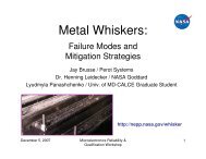


![mil-std-2223 [test methods for insulated electric wire] - NEPP](https://img.yumpu.com/4036001/1/190x249/mil-std-2223-test-methods-for-insulated-electric-wire-nepp.jpg?quality=85)