

Thermal and Mechanical Reliability of Five COTS MEMS - NASA ...
Thermal and Mechanical Reliability of Five COTS MEMS - NASA ...
Thermal and Mechanical Reliability of Five COTS MEMS - NASA ...

You also want an ePaper? Increase the reach of your titles
YUMPU automatically turns print PDFs into web optimized ePapers that Google loves.
ABSTRACT<br />
<strong>Thermal</strong> <strong>and</strong> <strong>Mechanical</strong> <strong>Reliability</strong> <strong>of</strong> <strong>Five</strong> <strong>COTS</strong> <strong>MEMS</strong> Accelerometers<br />
Reza Ghaffarian, Ph.D.<br />
Jet Propulsion Laboratory<br />
David G. Sutton, Paul Chaffee, <strong>and</strong> Nick Marquez<br />
The Aerospace Corporation<br />
Ashok K. Sharma<br />
Goddard Space Flight Center/<strong>NASA</strong><br />
Alex<strong>and</strong>er Teverovsky, Ph.D.<br />
QSS Group, Inc./<strong>NASA</strong><br />
Micro-electro-mechanical sensor systems (<strong>MEMS</strong> Sensors) are being considered for a variety <strong>of</strong> applications in space <strong>and</strong><br />
launch operations. These applications include health <strong>and</strong> status monitoring, environmental monitoring, automated control,<br />
repair <strong>and</strong> service. A microaccelerometer performance was characterized in detail <strong>and</strong> their failure mechanisms were<br />
identified by subjecting them to 1,000 thermal cycles under extreme temperatures (-65 to +150°C) <strong>and</strong> to 30,000 shocks at<br />
2,000 g. In addition, several other <strong>MEMS</strong> sensors (microaccelerometers <strong>and</strong> temperature sensors) were characterized at the<br />
extremes <strong>of</strong> their temperature ranges. It consists <strong>of</strong> a 10-day test that subjected various microaccelerometers to both<br />
continuous thermal cycling between temperatures <strong>of</strong> -40 °C <strong>and</strong> +85 °C <strong>and</strong> mechanical loading. A comparison <strong>of</strong> the data<br />
from microaccelerometers <strong>of</strong> the same type <strong>and</strong> between several types will be presented. Self-test output signals <strong>and</strong> X-ray<br />
evaluation test data after completion <strong>of</strong> 182 thermal cycles will also be presented.<br />
INTRODUCTION<br />
<strong>MEMS</strong> Definition <strong>and</strong> Applications<br />
Microelectromechanical systems (<strong>MEMS</strong>), also known as microsystems technology (MST) or micromachines, are integrated<br />
micro devices or systems combining electrical, mechanical, fluidic, optical, (<strong>and</strong> all physical domains) components fabricated<br />
using integrated circuit (IC) compatible batch-processing techniques <strong>and</strong> range in size from micrometers to millimeters.<br />
Miniaturization <strong>of</strong> mechanical systems promises unique opportunities for new directions in the progress <strong>of</strong> science <strong>and</strong><br />
technology. Micromechanical devices <strong>and</strong> systems are inherently smaller, lighter, faster, <strong>and</strong> usually more precise than their<br />
macroscopic counterparts. However, the development <strong>of</strong> micromechanical systems requires appropriate fabrication<br />
technologies that enable the features such as definition <strong>of</strong> small geometries, precise dimensional control, design flexibility,<br />
interfacing with control electronics, repeatability, reliability, <strong>and</strong> high yield <strong>and</strong> low cost per device will enable the <strong>MEMS</strong><br />
advanced technologies for the systems in the 21 st century.<br />
The majority <strong>of</strong> today’s <strong>MEMS</strong> products are components or subsystems <strong>and</strong> their main emphases are on the system levels.<br />
Current devices include accelerometers, pressure, chemical, <strong>and</strong> flow sensors, micromirrors, gyroscopes, fluid pumps, <strong>and</strong><br />
inkjet print heads. Current <strong>MEMS</strong> devices for electronic <strong>and</strong> optical applications include RF <strong>MEMS</strong> switches, optical<br />
network, <strong>and</strong> thermal sensors. Future <strong>and</strong> emerging applications include high-resolution displays, high-density data storage<br />
devices, etc. Current technology mainly addresses millimeter (mm) to micrometer (�m) level <strong>MEMS</strong> devices. Devices are<br />
being further developed in the range <strong>of</strong> submicron to nanometer scale (nano electromechanical systems, NEMS) for various<br />
applications.<br />
Sensors <strong>and</strong> Accelerometer<br />
Sensors <strong>and</strong> actuators are the two main categories <strong>of</strong> <strong>MEMS</strong>. Sensing systems are used for process control <strong>and</strong> measurement<br />
instrumentation. A transducer is used for both the input <strong>and</strong> the output blocks <strong>of</strong> the sensing system. The role <strong>of</strong> the input<br />
transducer is to get information or sense from the real world about the physical or chemical quantity. This is the reason why
input transducers are commonly called sensors. Often the electrical signals generated by sensors are weak <strong>and</strong> have to be<br />
amplified or processed in some way. This is done by the signal processing.<br />
For example, accelerometers are widely used for navigational <strong>and</strong> airbag deployment safety systems in automobiles. The<br />
current generation <strong>of</strong> accelerometer devices integrates electronic circuitry with a micromechanical sensor to provide selfdiagnostics<br />
<strong>and</strong> digital output. It is anticipated that the next generation <strong>of</strong> devices will also incorporate the entire airbag<br />
deployment circuitry that decides whether to inflate the airbag. As the technology matures, the airbag crash sensor may be<br />
integrated one day with micromachined sensors to form a complete microsystem responsible for driver safety <strong>and</strong> vehicle<br />
stability.<br />
A <strong>MEMS</strong> solution with lighter weight becomes attractive, if it enables a new function, provides significant cost reduction, or<br />
both. Space operations will benefit from the comparatively low mass, volume <strong>and</strong> power required by <strong>MEMS</strong>. In addition,<br />
<strong>MEMS</strong> are <strong>of</strong>ten simple <strong>and</strong> cheap to produce, install <strong>and</strong> operate. However, space <strong>and</strong> launch operations require extremely<br />
high reliability <strong>and</strong> trustworthiness from their systems, especially in human space exploration. MEM devices can <strong>of</strong>ten be<br />
deployed redundantly to decrease their reliability risk without inflicting large claims on scarce resources. In addition, most<br />
microdevices have self-test or diagnostic features as integral capabilities. The task for the systems designer is to use these<br />
characteristics (compactness, redundancy, self-test) to extend the lifetime <strong>of</strong> <strong>MEMS</strong>, while at the same time enhancing their<br />
reliability <strong>and</strong> trustworthiness.<br />
Purpose <strong>of</strong> This Investigation<br />
Packaging <strong>and</strong> testing <strong>of</strong> integrated circuit (IC) is well advanced because <strong>of</strong> the maturity <strong>of</strong> the IC industry, their wide<br />
applications, <strong>and</strong> availability <strong>of</strong> industrial infrastructure. 1 This is not true for <strong>MEMS</strong> with respect to packaging <strong>and</strong> testing 2 .<br />
It is more difficult to adopt st<strong>and</strong>ardized <strong>MEMS</strong> device packaging for wide applications, although <strong>MEMS</strong> use many similar<br />
technologies to IC packaging. Packaging <strong>of</strong> <strong>MEMS</strong> devices is more complex since in some cases it needs to provide<br />
protection from the environment while in some cases allowing access to the environment to measure or affect the desired<br />
physical or chemical parameters. Most <strong>of</strong> the silicon circuitry is sensitive to temperature, moisture, magnetic field, light, <strong>and</strong><br />
electromagnetic interference. Microscopic mechanical moving parts <strong>of</strong> <strong>MEMS</strong> also have their unique issues. Therefore,<br />
testing <strong>MEMS</strong> packages using the same methodologies, as those for electronics packages with st<strong>and</strong>ard procedures might not<br />
always be possible especially when quality <strong>and</strong> reliability need to be assessed.<br />
<strong>MEMS</strong> package reliability depends on the package type, i.e. ceramic, plastic, or metal, <strong>and</strong> the reliability <strong>of</strong> the device. The<br />
<strong>MEMS</strong> device reliability depends on its materials <strong>and</strong> wafer level processes <strong>and</strong> the sealing methods used for environmental<br />
protection. Key package reliability issues were reviewed in a previous paper <strong>and</strong> needs for underst<strong>and</strong>ing characterization<br />
<strong>and</strong> failure mechanisms were identified. Implementation <strong>of</strong> conventional IC reliability to determine if they could accelerate<br />
<strong>MEMS</strong> accelerometer failure was discussed in a recent paper 4 . It was found that while mechanical stresses were more<br />
effective in inducing <strong>MEMS</strong> related failures, some traditional reliability tests did accelerate <strong>MEMS</strong>-related failure.<br />
This study utilizes conventional environmental tests in a synergistic approach to determine reliability issues associated with<br />
commercial-<strong>of</strong>f-the-shelf packages. <strong>COTS</strong> accelerometers <strong>and</strong> temperature sensors were considered for evaluation in order<br />
to be able to use a large number <strong>of</strong> them, therefore generating meaningful statistical reliability data, <strong>and</strong> determining their<br />
associated risk. In addition, it is hoped that comparative performance analysis will identify aberrations or self-test signals that<br />
will serve to flag the onset <strong>of</strong> false readings or device failure. Data <strong>of</strong> this nature will be invaluable for quality assurance <strong>and</strong><br />
risk mitigation by formulating the s<strong>of</strong>tware to assess the veracity <strong>of</strong> signals from individual sensors <strong>and</strong> build reliable<br />
scenarios from networked systems. This paper will include a large number <strong>of</strong> test data gathered under thermal <strong>and</strong><br />
mechanical loading for a variety <strong>of</strong> <strong>MEMS</strong> sensors.<br />
ACCELEROMETER TYPES<br />
Numerous packages were subjected to environmental characterization. The devices under test included accelerometers<br />
manufactured by:<br />
� Motorola Semiconductor Products<br />
� Analog Devices, Inc.<br />
� Kistler Instrument Corporation<br />
Additionally, temperature measurement devices from Analog Devices <strong>and</strong> Dallas Semiconductor were tested <strong>and</strong> used to<br />
monitor temperatures within the test chamber. The Analog Device AXDL 250 was characterized at GSFC under the <strong>NASA</strong><br />
Electronic Parts <strong>and</strong> Packaging (NEPP) 5 program A summary <strong>of</strong> this characterization is also shown below. The other four
accelerometers <strong>and</strong> temperature device characterizations were performed by the Aerospace Corporation for <strong>NASA</strong>/Johnson<br />
Space Center. They also collaborated with JPL under the NEPP program 6 . In the following, after discussion on AXDL 250,<br />
the test procedures <strong>and</strong> results <strong>of</strong> thermal <strong>and</strong> mechanical experiments for the other four accelerometers will be presented.<br />
CHARACTERIZATION ADXL 250<br />
Package Description<br />
Analog Devices ADXL250 is a dual-axis, surface micromachined accelerometer rated for � 50 g <strong>and</strong> packaged in a hermetic<br />
14-lead surface mount Cerpack. The operating temperature range <strong>of</strong> the part is from –55 �C to +125 �C <strong>and</strong> the storage<br />
temperature range is from –65 �C to +150 �C. The part can withst<strong>and</strong> acceleration up to 2000 g.<br />
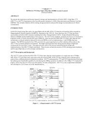
The device is fabricated using a proprietary surface micromachining process that has been in high volume production at<br />
Analog Devices, since 1993. The two sensitive axes <strong>of</strong> the ADXL250 are orthogonal (90�) to each other <strong>and</strong> in the same<br />
plane as the silicon chip. The differential capacitor sensor consists <strong>of</strong> fixed plates (stationary polysilicon fingers) <strong>and</strong> moving<br />
plates attached to the beam (inertial mass) that shifts in response to the acceleration. Movement <strong>of</strong> the beam changes the<br />
differential capacitance, which is measured by the on-chip circuitry (the clock frequency <strong>of</strong> the capacitance meter is 1 MHz).<br />
Figures 1 provides an overview <strong>of</strong> the chip <strong>and</strong> the capacitive sensor with the close up views <strong>of</strong> the elements <strong>of</strong> the sensor<br />
including spring attachment <strong>and</strong> polysilicon finger attachment.<br />
Finger<br />
Figure 1: ADXL250 Capacitive Micromachined Accelerometer<br />
<strong>Thermal</strong> Cycling Characterization<br />
Temperature cycling was performed on 10 parts, in the range <strong>of</strong> –65 �C to +150 �C, with 15 minutes dwell time at each<br />
temperature. Measurements were taken after 100, 200, 400, 700, <strong>and</strong> 1000 cycles. No significant changes were observed<br />
with thermal cycling. Other electrical parameters showed a similar trend.<br />
<strong>Mechanical</strong> Shock Behavior<br />
Spring Attachment<br />
<strong>Mechanical</strong> shock testing was performed on two groups <strong>of</strong> devices with ten samples in each group. The first group was<br />
subjected to 2000 g shocks in X-direction <strong>and</strong> the second group to 2000 g shocks in Z-direction. Measurements were taken<br />
after 100, 300, 1000, 3,000, 10,000, <strong>and</strong> 30,000 shocks.<br />
Except for one sample <strong>of</strong> the first group, which failed after 10,000 shocks, all other retained their integrity to 30,000 shocks<br />
with only minor changes in their parameters.
All samples, except for the failed one, passed PIND testing. The failed part exhibited permanent noise bursts indicating<br />
presence <strong>of</strong> free particles inside the cavity.<br />
Failure Analysis<br />
The failed part <strong>and</strong> several good parts from different groups were decapsulated after testing <strong>and</strong> examined using optical <strong>and</strong><br />
SEM microscopes. No microcracks or other defects, which would indicate fatigue-related damage in the sensors, were<br />
observed in any <strong>of</strong> the parts.<br />
A site with a structural anomaly was found in the sealing glass <strong>of</strong> the failed device. This site had excessive voiding <strong>and</strong><br />
porosity, which most likely was due to a contaminant embedded in the glass. Additionally, Electron beam induced current<br />
technique (EBIC) was used in an attempt to find any anomaly in the failed Y-channel electronic circuit as compared to the Xchannel.<br />
EBIC images <strong>of</strong> the two channels were similar, suggesting that no damage to electronics had occurred.<br />
A small particle with a size <strong>of</strong> approximately 1 �m, which most likely chipped out from the package, was found jammed<br />
between the comb fingers in the Y-channel sensor in the failed part. This particle appears to have wedged electrodes <strong>of</strong> the<br />
capacitor sensor, causing the Y output to be stuck high.<br />
CHARACTERIZATION OF FOUR ACCELEROMETERS<br />
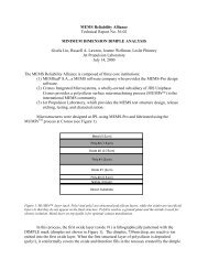
Four other accelerometers were mounted on two boards as shown in Figure 2. The Motorola accelerometers on boards 1 <strong>and</strong><br />
2 were mounted in a 16 pin DIP sockets which were wire-wrapped to a 40-pin header socket mounted on each board. The<br />
Kistler accelerometer on each board was wired directly to the 40-pin header socket. The Analog accelerometers were<br />
packaged in 10-pin TO-100 metal Cans which were inserted into 10 pin sockets <strong>and</strong> mounted vertically on each board.<br />
The thermal test was designed to determine the thermal stability characteristics <strong>of</strong> accelerometers at temperatures <strong>of</strong> -40 <strong>and</strong><br />
+85°C. Accelerometers were mounted on fiberglass circuit boards <strong>and</strong> thermally cycled in a Delta Design Model 9039<br />
environmental test chamber. This chamber has a built-in heater <strong>and</strong> is chilled using liquid nitrogen (LN2). The chamber<br />
temperature was controlled with a thermocouple <strong>and</strong> a Macintosh computer using a LabView program.<br />
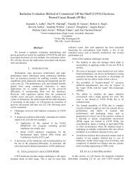
Figure 3 shows temperature data for the first two cycles that are recorded at one-minute intervals. The sawtooth pattern was<br />
programmed into the test chamber to allow ample time for temperature stabilization <strong>and</strong> equilibration at the extremes. After<br />
an initial ramp up to +85°C over a period <strong>of</strong> 10 minutes, the devices were soaked at that temperature for a period <strong>of</strong> 20<br />
minutes.<br />
•<strong>Thermal</strong><br />
sensors on<br />
board 4<br />
• Accelerometer<br />
on board 2<br />
• Motor driven<br />
cam for<br />
mechanical<br />
excitation <strong>of</strong><br />
board 1<br />
Figure 2: <strong>Thermal</strong> Cycling experimental test set up with motor driven cam for mechanical excitation<br />
The temperature was then ramped down to -40 °C over a 20-minute period <strong>and</strong> the devices were then held at that temperature<br />
for 20-minutes. At the end <strong>of</strong> that time, the temperature was ramped up for 20-minutes to +85 °C to repeat the cycle. Each<br />
full cycle took approximately 80-minutes, divided into four 20-minute segments. This sequence continued for 10 days, 182<br />
cycles.
100<br />
80<br />
60<br />
40<br />
20<br />
0<br />
-20<br />
-40<br />
-60<br />
Fast Data<br />
Acquistion<br />
Begins<br />
0:00 0:30 1:00 1:30 2:00 2:30<br />
Elapsed Time (hours:minutes)<br />
Figure 3: <strong>Thermal</strong> pr<strong>of</strong>ile for accelerometers attached on board<br />
<strong>Mechanical</strong> excitation was applied through the free end <strong>of</strong> fiberglass circuit boards. Boards 1 <strong>and</strong> 2 were bolted at one end to<br />
a short metal extension held in an aluminum block, which was bolted to the shelf attached to the door <strong>of</strong> the test chamber. A<br />
motor driven cam mechanism was used to periodically displace the opposite, free ends <strong>of</strong> these two boards approximately 3/4<br />
inches in the vertical direction <strong>and</strong> then released them to freely vibrate. Upon release, the resulting board motion was that <strong>of</strong><br />
a damped vibration <strong>of</strong> a cantilevered beam which yields alternating accelerations in the vertical direction.<br />
The devices mounted on each <strong>of</strong> the two boards recorded these accelerations. Boards 1 <strong>and</strong> 2 were excited to motion once<br />
approximately 15 minutes into each temperature soak on every thermal cycle. The two other boards were attached directly to<br />
a shelf on the oven door <strong>and</strong> were not mechanically manipulated.<br />
The outputs <strong>of</strong> the devices were recorded using a National Instruments AT-MIO-64F-5 data acquisition board <strong>and</strong> LabView<br />
s<strong>of</strong>tware under Windows NT operating on a personal computer (PC) using a Pentium microprocessor. The data were stored<br />
in files on the hard drive <strong>of</strong> the computer.<br />
Test Results<br />
Figure 4 shows data from three different microaccelerometers recorded during the same oscillation event triggered on cycle 1<br />
at +85°C. Due to differences in the individual sensors, the three curves appear to be different, but they have faithfully<br />
recorded similar accelerations. The Motorola XMMAS40 sensor is eight times less sensitive than the Analog Devices<br />
ADXL05J, so on this scale, the response is proportionately less. In addition, the ADXL05J appears to be out <strong>of</strong> phase with<br />
the other two sensors. The signal from the ADXL05J is inverted relative to the other two devices due to its opposite<br />
orientation on the board.<br />
4.5<br />
4<br />
3.5<br />
3<br />
2.5<br />
2<br />
1.5<br />
1<br />
0.5<br />
Accelerometer Response<br />
Cycle 1, 85 deg C<br />
Board Released From Cam<br />
0<br />
0 200 400<br />
Time (msec)<br />
600 800 1000<br />
Kistler MMA40 #1 ADXL05 #1<br />
Figure 4: Range <strong>of</strong> responses for three accelerometers at hot temperature
3.5<br />
3<br />
2.5<br />
2<br />
1.5<br />
1<br />
0.5<br />
0<br />
0 200 400 600 800 1000<br />
Time (msec)<br />
ADXL05 #1, +85 deg C ADXL05 #1, -40 deg C<br />
Figure 5: Responses at temperature extremes for ADXL05 Accelerometer at cycle 1<br />
Figure 5 shows the response <strong>of</strong> the Analog Devices ADXL05J microaccelerometer to two successive events; namely the<br />
+85°C <strong>and</strong> the -40°C extremes <strong>of</strong> cycle 1. There is a delay between these two events <strong>of</strong> 40 minutes, while the temperature<br />
drops. The data at +85°C is the same as that shown for ADXL05J #1 in Figure 4.<br />
A comparison <strong>of</strong> the two curves in Figure 5 shows behavior that can be explained by the effects <strong>of</strong> temperature variations on<br />
the aluminum hinge used to mount the board. The peak amplitudes in the acceleration are smaller <strong>and</strong> the frequency is<br />
slightly higher in the event at -40°C as compared to the one at +85°C. The frequency <strong>of</strong> an oscillating cantilevered beam is<br />
expected to increase as the square root <strong>of</strong> the bending modulus. Thus, if the modulus increases as the temperature is reduced,<br />
we would expect an increase in the frequency. This is the case for aluminum. The mechanics <strong>of</strong> our test boards are more<br />
complicated, because they are effectively compound beams <strong>of</strong> thin aluminum joined to a thick fiberglass test board.<br />
However, we expect the temperature trend to be the same <strong>and</strong> indeed observe a higher frequency at the lower temperature for<br />
every case examined.<br />
NON DESTRUCTIVE CHARACTERIZATION BY X-RAY<br />
Non-destructive evaluation using a real time X-ray was performed prior to <strong>and</strong> after about 182 thermal cycles to assure the<br />
quality <strong>of</strong> the packages. A representative <strong>of</strong> X-ray photos for accelerometers are shown in Figures 6. No failures or<br />
particulates that may represent gross failures were observed. After establishing such baseline, these accelerometers will be<br />
further subjected to thermomechanical exposure till failure.<br />
Figure 6: Kistler Accelerometers, as received <strong>and</strong> after 200 cycles<br />
As Received<br />
200 Cycles
CONCLUSIONS<br />
� Analog devices ADXL250 successfully passed 1,000 thermal cycles in the range <strong>of</strong> –65°C to +150°C, as well as 30,000<br />
mechanical shocks <strong>of</strong> 2000 g in the Z-direction <strong>and</strong> 10,000 shock in the X-direction with minor parametric changes.<br />
� Four accelerometers: Motorola XMMAS40G, MMA1201P, Analog devices ADXL05J, Kistler 8303A1, <strong>and</strong> a<br />
temperature sensor performed within their nominal specification. They showed no degradation verified by electrical <strong>and</strong><br />
non-destructive evaluation when subjected to 182 cycles in the range <strong>of</strong> –40°C to +85°C. This temperature regime was<br />
higher than operating temperatures <strong>of</strong> ADXL05J <strong>and</strong> 8303A1 accelerometers.<br />
ACKNOWLEDGEMENTS<br />
Portions <strong>of</strong> the research described in this publication were carried out by the Jet Propulsion Laboratory, California Institute <strong>of</strong><br />
Technology, under a contract with the National Aeronautics <strong>and</strong> Space Administration. It is funded under <strong>NASA</strong> Electronic<br />
Parts <strong>and</strong> Packaging Program (NEPP). Continuous support <strong>and</strong> encouragement by Dr. Charles Barnes, NEPP Program<br />
Manger, is appreciated.<br />
REFERENCES<br />
1. Ghaffarian, R. "Chip Scale Packaging Guidelines & Ball Grid Array Guidelines,” Interconnection Technology Research<br />
Institute (ITRI), Jan. 2000, http://www.ITRI.org<br />
2. Ramesham, R.,Ghaffarian, R., Ayazi, F.,"Fundamentals <strong>of</strong> Microelectromechanical Systems,” Chapter 14, Microsystems<br />
Packaging Book by Rao Tummala, McGraw-Hill, 2001, ISBN0-07-137169-9<br />
3. Ghaffarian, R., Ramesham, R.”Comparison <strong>of</strong> IC <strong>and</strong> <strong>MEMS</strong> Packaging <strong>Reliability</strong> Approaches,” Surface Mount<br />
Technology Association, Chicago, 2000<br />
4. Delak, K.M., et al., “Analysis <strong>of</strong> Manufacturing Scale <strong>MEMS</strong> <strong>Reliability</strong> Testing,” <strong>MEMS</strong> <strong>Reliability</strong> for Critical <strong>and</strong><br />
Space Applications, SPIE Volume 3880, Santa Clara, Sept. 1999<br />
5. Sharma, A., Teverovksy, “Evaluation <strong>of</strong> thermo-mechanical Stability <strong>of</strong> <strong>COTS</strong> Dual-Axis <strong>MEMS</strong> Accelerometers for<br />
Space Applications,” <strong>COTS</strong> <strong>MEMS</strong> Conf., Knowledge Foundation, Berkley, August, 2000<br />
6. Sutton, D.G., Chaffee,P., Marquez, N., Ghaffarian, R.., “<strong>Reliability</strong> Risk Assessment <strong>of</strong> <strong>COTS</strong> <strong>MEMS</strong> Accelerometer<br />
Under Thermomechanical Cycling,” Aerospace Corporation Report No. TOR-200(2124)-2


![mil-std-2223 [test methods for insulated electric wire] - NEPP](https://img.yumpu.com/4036001/1/190x249/mil-std-2223-test-methods-for-insulated-electric-wire-nepp.jpg?quality=85)