Reliability Evaluation of PEMs Rejected During C-SAM - NASA ...
Reliability Evaluation of PEMs Rejected During C-SAM - NASA ...
Reliability Evaluation of PEMs Rejected During C-SAM - NASA ...
You also want an ePaper? Increase the reach of your titles
YUMPU automatically turns print PDFs into web optimized ePapers that Google loves.
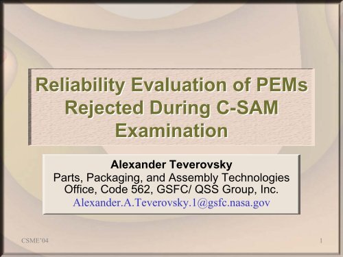
<strong>Reliability</strong> <strong>Evaluation</strong> <strong>of</strong> <strong>PEMs</strong><br />
<strong>Rejected</strong> <strong>During</strong> C-<strong>SAM</strong><br />
Examination<br />
Alexander Teverovsky<br />
Parts, Packaging, and Assembly Technologies<br />
Office, Code 562, GSFC/ QSS Group, Inc.<br />
Alexander.A.Teverovsky.1@gsfc.nasa.gov<br />
CSME’04 1
Acknowledgements<br />
This work was sponsored by the GSFC projects<br />
and <strong>NASA</strong> Electronic Parts and Packaging (NEPP)<br />
program.<br />
The author would like to thank GSFC Parts<br />
Engineers Bruce Meinhold and Gerry Kiernan for<br />
providing samples for this work and initial C-<strong>SAM</strong><br />
images.<br />
The author acknowledges his debt to engineers<br />
and technicians <strong>of</strong> the Parts, Packaging, and<br />
Assembly Technologies Office, Code 562, GSFC,<br />
for help with testing, and to Darryl Lakins, Branch<br />
Head <strong>of</strong> Code 562, for support <strong>of</strong> this work.<br />
CSME’04 2
Purpose and Outline<br />
Purpose:<br />
To discuss effectiveness <strong>of</strong> C-<strong>SAM</strong> examinations during<br />
screening <strong>of</strong> low-power devices in SOIC8 packages and<br />
power devices in TO-220 and SOT-223 style packages.<br />
Outline:<br />
� General problems with C-<strong>SAM</strong>.<br />
� Description <strong>of</strong> C-<strong>SAM</strong> rejects used for experiments.<br />
� <strong>Reliability</strong> testing conditions and results.<br />
� Conclusion.<br />
CSME’04 3
Which Part to Choose?<br />
Delaminations are due to stress relief in <strong>PEMs</strong>.<br />
Typically rejected<br />
Typically accepted<br />
Before stress. After stress? Before stress. After stress?<br />
This part might operate<br />
reliably because<br />
mechanical stresses have<br />
been relieved and<br />
delaminations are stable.<br />
This part might fail if the<br />
stresses have not been<br />
relieved and delaminations<br />
develop in critical wire bond<br />
areas.<br />
� Some types <strong>of</strong> delaminations might be not harmful.<br />
� If delaminations are serious defects, is it possible to improve<br />
reliability <strong>of</strong> a lot with 5% to 50% rejects by screening?<br />
CSME’04 4
More Provocative Questions<br />
Regarding Acoustic Microscopy<br />
If no delaminations were observed by screening:<br />
� Can they appear after soldering reflow, TC,<br />
environmental stresses, operation, …?<br />
� Can they develop reversibly at high/low temperatures<br />
or during moisture sorption/desorption?<br />
What if there is a sponge-like<br />
structure at the interface?<br />
How reliable is C-<strong>SAM</strong> data?<br />
How <strong>of</strong>ten do delaminations self-heal?<br />
How risky are different types <strong>of</strong> delaminations?<br />
CSME’04 5
Is C<strong>SAM</strong> Testing Non-Destructive?<br />
Each handling has the probability <strong>of</strong> ~0.1% <strong>of</strong> ESD<br />
damaging the parts. This number might be larger for<br />
low voltage microcircuits.<br />
Requirements for the cleanliness <strong>of</strong> water are not<br />
always enforced.<br />
To screen large-quantity lots, the<br />
parts are installed on a sticky<br />
plate. This might contaminate<br />
leads and mechanically damage<br />
small parts.<br />
Special holders to avoid damage<br />
are not always available.<br />
CSME’04 6
Description <strong>of</strong> Parts Used<br />
Part Package<br />
Die<br />
coating<br />
Total<br />
QTY<br />
Rejects,<br />
%<br />
Type <strong>of</strong><br />
delam.<br />
PEM1 SOIC8 silicone 712 83% P, L<br />
PEM2 SOIC8 silicone 469 20% P, L<br />
PEM3 SOIC8 silicone 2143 5.1% P, L<br />
PEM4 SOIC8 - 463 32.2% P, L<br />
PEM5 SOIC8 silicone 297 18.9% P, L<br />
FET1 D2pak - 995 14.6% P, L, D<br />
FET2 D2pak - 200 28% P, L, D<br />
FET3 SOT223 - 895 10.5% P, L<br />
Delaminations:<br />
P - top <strong>of</strong> paddle; L – leads at wire bonds; D – top <strong>of</strong> die.<br />
CSME’04 7
Typical AM Images<br />
(Linear Devices, SOIC8 Packages)<br />
PEM1 PEM2<br />
PEM2 had 2 WBs to the<br />
paddle, which might<br />
cause failures if broken.<br />
PEM3 PEM4 PEM5<br />
CSME’04 8
Typical AM images (Power FETs)<br />
FETs 1 and 2 have<br />
Al wire bonds.<br />
Characteristics <strong>of</strong><br />
molding compound:<br />
Tg = 165 o C<br />
CTE1 = 21.5 ppm/ o C<br />
FET3 has<br />
Au wire bonds.<br />
Characteristics <strong>of</strong><br />
molding compound:<br />
Tg = 155 o C<br />
CTE1 = 16.4 ppm/ o C<br />
CSME’04 9
Testing <strong>of</strong> AM Rejects<br />
Thirty samples <strong>of</strong> each part type rejected by C-<strong>SAM</strong><br />
screening were electrically tested, environmentally<br />
stressed, and examined using acoustic microscopy:<br />
� Before testing.<br />
� After SMT simulation and preconditioning per JEDEC<br />
JESD22-A113 (85 o C/85% RH/168 hrs +3 runs<br />
through IR reflow chamber+ flux application and<br />
rinsing).<br />
� After 100, 300, and 1000 temperature cycles<br />
between –55 and +125 o C (condition TC0).<br />
� After 100 and 300 cycles between 0 and 180 o C<br />
(condition TC1).<br />
� After 100 and 300 cycles between 20 and 200 o C<br />
(condition TC2).<br />
CSME’04 10
Examples <strong>of</strong> AM Images Before and<br />
After Stress Testing (Linear Devices)<br />
PEM1<br />
PEM4<br />
PEM5<br />
init after SMT after 1000 TC<br />
The proportion<br />
<strong>of</strong> delaminated<br />
area<br />
decreased<br />
after SMT and<br />
increased after<br />
temperature<br />
cycling.<br />
CSME’04 11
Changes in Delaminations Due to<br />
Stress Testing (Linear Devices)<br />
Proportion <strong>of</strong> delaminations, %<br />
Proportion <strong>of</strong> delaminations, %<br />
80<br />
60<br />
40<br />
20<br />
0<br />
100<br />
80<br />
60<br />
40<br />
20<br />
0<br />
PEM1<br />
PEM3<br />
PEM5<br />
PEM4<br />
init after SMT 1000 TC<br />
init after SMT 1000 TC<br />
Lead-to-MC<br />
delaminations<br />
Paddle-to-MC<br />
delaminations<br />
CSME’04 12
Examples <strong>of</strong> AM Images Before and<br />
After Stress Testing (Power Devices)<br />
FET 1die<br />
FET 1 lead frame<br />
FET 3<br />
init after SMT after 1000 TC after HT TC<br />
CSME’04 13
Changes in Delaminations Due to<br />
Stress Testing (Power Devices)<br />
delaminations, %<br />
delaminations, %<br />
60<br />
40<br />
20<br />
0<br />
100<br />
80<br />
60<br />
40<br />
20<br />
0<br />
Die surface Leads<br />
init after SMT after 1000<br />
TC<br />
Top paddle<br />
FET2<br />
FET1<br />
FET3<br />
init after SMT after 1000<br />
TC<br />
after HT TC<br />
after HT TC<br />
CSME’04 14<br />
delaminations, %<br />
100<br />
80<br />
60<br />
40<br />
20<br />
0<br />
init after SMT after 1000<br />
TC<br />
FET2<br />
FET1<br />
FET3<br />
after HT<br />
TC<br />
� No top-<strong>of</strong>-die delaminations<br />
(TODD) in FET3.<br />
� In FETs 1 and 2 TODD<br />
increased and paddle<br />
delaminations decreased<br />
after SMT.
VOS, uV<br />
Results <strong>of</strong> Electrical Testing<br />
(Operational Amplifiers)<br />
Offset voltage variation<br />
during temperature cycling<br />
200<br />
100<br />
0<br />
-100<br />
-200<br />
PEM3<br />
PEM4<br />
PEM1<br />
PEM5<br />
init SMT 100 TC 300 TC 1000<br />
TC<br />
100 TC<br />
H<br />
100 TC<br />
H2<br />
300 TC<br />
H2<br />
Input bias current variation<br />
during temperature cycling<br />
1.E+06<br />
1.E+05<br />
1.E+04<br />
1.E+03<br />
1.E+02<br />
1.E+01<br />
1.E+00<br />
init SMT 100<br />
TC<br />
CSME’04 15<br />
IOSP, pA<br />
PEM3<br />
PEM4<br />
PEM1<br />
PEM5<br />
300<br />
TC<br />
1000<br />
TC<br />
100<br />
TC H<br />
The parts had no failures and manifested only<br />
minor parametric variations.<br />
100<br />
TC<br />
H2<br />
300<br />
TC<br />
H2
Results <strong>of</strong> Electrical Testing<br />
(Voltage References)<br />
Vout, V<br />
2.501<br />
2.5005<br />
2.5<br />
2.4995<br />
2.499<br />
Average output voltages<br />
no load<br />
load 10 mA<br />
init SMT 100 TC300 TC 1000<br />
TC<br />
100 TC<br />
H<br />
100 TC300<br />
TC<br />
H2 H2<br />
CSME’04 16<br />
2.5<br />
2.495<br />
2.49<br />
2.485<br />
2.48<br />
2.475<br />
� Devices had minor parametric variations.<br />
� One part failed at load conditions after 100 HT TC.<br />
Vout load, V
VTH, V<br />
IGP, A<br />
4<br />
3.5<br />
3<br />
2.5<br />
2<br />
1.5<br />
1<br />
Results <strong>of</strong> Electrical<br />
Measurements (Power FET)<br />
1.E-06<br />
1.E-07<br />
1.E-08<br />
1.E-09<br />
1.E-10<br />
1.E-11<br />
1.E-12<br />
Average threshold voltage<br />
FET1<br />
FET2<br />
FET3<br />
Average gate current<br />
init<br />
after SMT<br />
100 TC<br />
300 TC<br />
1000 TC<br />
100 TC H<br />
300 TC H<br />
100 TC H<br />
300 TC H<br />
FET1<br />
FET2<br />
FET3<br />
init<br />
after SMT<br />
100 TC<br />
300 TC<br />
1000 TC<br />
100 TC H<br />
300 TC H<br />
100 TC H<br />
300 TC H<br />
� No failures after TC.<br />
� No VTH variations.<br />
� Significant increase<br />
in leakage currents<br />
after SMT simulation.<br />
� All failed parts<br />
recovered after TC.<br />
� Some failed parts<br />
had corrosion <strong>of</strong> Al<br />
metallization after<br />
HAST.<br />
CSME’04 17
Results <strong>of</strong> Temperature Cycling <strong>of</strong><br />
Parts with Excessive Delaminations<br />
Part SMT TC0 100 TC0 300<br />
TC0 1k TC1 300 TC2 300<br />
PEM1 0/30 0/30 0/30 0/30 0/15 0/15<br />
PEM2 0/30 0/30 0/30 0/30 1/15 1/15<br />
PEM3 0/30 0/30 0/30 0/30 0/15 0/15<br />
PEM4 0/30 0/30 0/30 0/30 0/15 0/15<br />
PEM5 0/30 0/30 0/30 0/30 0/15 0/15<br />
FET1 0/30 0/30 0/30 0/30 0/15 0/15<br />
FET2 0/30 0/30 0/30 0/30 0/15 0/15<br />
FET3 0/30 0/30 0/30 0/30 0/15 0/15<br />
PEM6* 0/30 0/30 0/30 0/30 - -<br />
*Parts had excessive delaminations at finger-tips after HAST.<br />
CSME’04 18
IG S P , A<br />
Effect <strong>of</strong> Flux Application on<br />
1.E-06<br />
1.E-08<br />
1.E-10<br />
1.E-12<br />
Power Devices<br />
Effect <strong>of</strong> flux application.<br />
init<br />
after flux<br />
applic ation<br />
15 hrs RT<br />
CSME’04 19<br />
87 hrs RT<br />
Test conditions:<br />
Immersion into<br />
KESTER 2331-ZX<br />
water-soluble flux<br />
for 10 seconds,<br />
rinsing, and blowing<br />
with dry air.<br />
Excessive leakage<br />
currents remained<br />
after a few days <strong>of</strong><br />
storing in laboratory<br />
conditions.
IG, A<br />
Effect <strong>of</strong> Flux Application on<br />
Power Devices, Cont’d<br />
1.E-06<br />
1.E-07<br />
1.E-08<br />
1.E-09<br />
1.E-10<br />
1.E-11<br />
1.E-12<br />
Failed samples.<br />
in it S MT s imul.<br />
+ C<strong>SAM</strong><br />
1 hr 125<br />
oC<br />
3 hr 125<br />
oC<br />
15 hr<br />
100% RH<br />
22 oC<br />
10 sec in<br />
deionized<br />
wa te r<br />
� Baking for a few<br />
hours at 125 o C<br />
mostly restored<br />
leakage currents.<br />
� Immersion in<br />
water and storing<br />
at 100%RH did<br />
not increase IG.<br />
� Effect <strong>of</strong> SMT<br />
simulation is likely<br />
due to good<br />
wettability <strong>of</strong> flux.<br />
� The type <strong>of</strong> flux used for SMT simulation might affect results <strong>of</strong><br />
qualification testing. JESD22-A113 might need a review.<br />
� Flux used for soldering might be different from the one used for<br />
the simulation, thus making results <strong>of</strong> qualification questionable.<br />
CSME’04 20
IG, A<br />
1.E-06<br />
1.E-07<br />
1.E-08<br />
1.E-09<br />
1.E-10<br />
1.E-11<br />
1.E-12<br />
Can C<strong>SAM</strong> Screen Out Flux-<br />
Related Failures?<br />
paddle delaminations<br />
Effect <strong>of</strong> immersion into flux<br />
0 20 40 60 80<br />
proportion <strong>of</strong> delamination, %<br />
1.E-06<br />
1.E-07<br />
1.E-08<br />
1.E-09<br />
1.E-10<br />
1.E-11<br />
1.E-12<br />
TODD<br />
0 20 40 60 80<br />
proportion <strong>of</strong> delamination, %<br />
No correlation between TODD or paddle-to-MC delaminations<br />
and leakage currents after flux immersion was observed.<br />
CSME’04 21<br />
IG, A
Conclusion<br />
Parts with excessive delaminations at the paddle and leads<br />
(at secondary bond locations) had no electrical failures after<br />
1000 TC at –55 to +125 o C conditions.<br />
The analyzed power devices in TO220-style packages are<br />
prone to formation <strong>of</strong> top-<strong>of</strong>-die delaminations; however, no<br />
wire bond fractures occurred even after multiple temperature<br />
cycling.<br />
Washable flux can penetrate to the die surface through<br />
delaminations significantly increasing leakage currents and<br />
causing corrosion <strong>of</strong> Al metallization.<br />
No correlation between the proportion <strong>of</strong> delaminations and<br />
flux-induced leakage currents were observed indicating a<br />
failure <strong>of</strong> C<strong>SAM</strong> examination to screen out potential failures.<br />
For the part types used, C<strong>SAM</strong> examination is not a valueadded<br />
technique for screening; however, it is very useful for<br />
qualification testing.<br />
CSME’04 22



![mil-std-2223 [test methods for insulated electric wire] - NEPP](https://img.yumpu.com/4036001/1/190x249/mil-std-2223-test-methods-for-insulated-electric-wire-nepp.jpg?quality=85)