Lab #4 Sequential Logic Design
Lab #4 Sequential Logic Design
Lab #4 Sequential Logic Design
Create successful ePaper yourself
Turn your PDF publications into a flip-book with our unique Google optimized e-Paper software.
Objective:<br />
<strong>Lab</strong> <strong>#4</strong> <strong>Sequential</strong> <strong>Logic</strong> <strong>Design</strong><br />
To study the behavior and applications of flip flops and basic sequential circuits including shift registers<br />
and counters.<br />
Preparation:<br />
Read the following experiment. It will save time if you enter the circuit designs for Parts 3, 4 and 5<br />
using the graphic design editor before coming to the lab. Bring your textbook to the lab!<br />
Devices used:<br />
sn74LS00 Quad 2-input NAND<br />
sn74LS76 Dual JK Master-slave flip flop<br />
2732A EPROM<br />
MAX3000 EPM3032ALC44-10 CPLD<br />
Digital-to-Analog converter (DAC)<br />
Op Amp<br />
Experiment:<br />
Latches and Flip-flops<br />
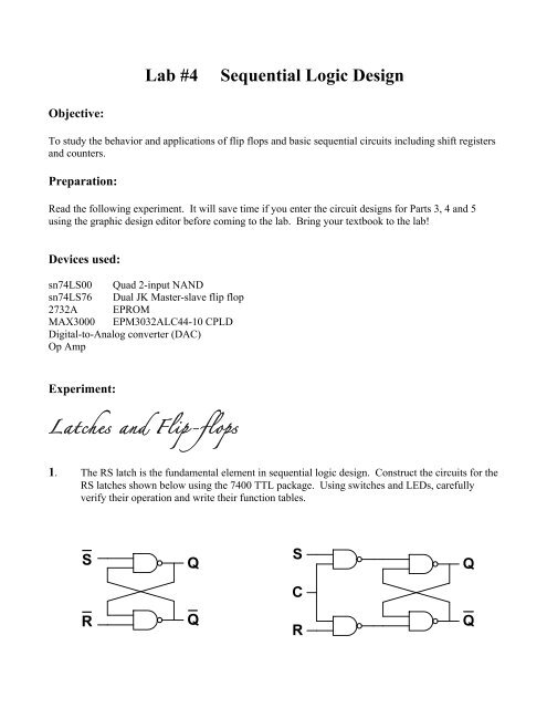
1. The RS latch is the fundamental element in sequential logic design. Construct the circuits for the<br />
RS latches shown below using the 7400 TTL package. Using switches and LEDs, carefully<br />
verify their operation and write their function tables.<br />
S<br />
R<br />
Q<br />
Q
2. The JK flip flop is a widely used Master-slave device that features in the design of many<br />
sequential circuits. It is versatile in that it may be easily used as a toggle flipflop ( T-type) or a D<br />
flipflop (D-type)<br />
(a) Carefully verify the behavior of the JK flipflop (in the 7476 TTL package) and write out its<br />
characteristic table. Note carefully the clock edge to which it responds as well as the<br />
asynchronous operation of the preset and clear inputs. Use toggle switches for the inputs and<br />
LEDs on the outputs.<br />
(b) Connect an inverter between the J and K inputs and verify that the operation is that of a D flip<br />
flop. Write its characteristic table.<br />
(c) Connect the J and K inputs together and verify that it operates as a T flip flop and write its<br />
characteristic table.<br />
Registers and Counters<br />
A register is a group of n flip-flops operating together whose outputs are considered to represent<br />
an n-bit binary number. A single flip-flop can be considered to be a single-bit register. The simplest<br />
form of a register is used to just capture and hold a value applied to its inputs (eg. the D inputs of D flipflops)<br />
in response to a "write" command (the clock pulse). However, registers may also be considered to<br />
be operational meaning that the value they hold may be altered in response to an external input. For<br />
example, an n-bit counter may be considered a register with the capability to increment (or decrement)<br />
its value. Another common example is shifting in which the values of individual bits are passed from<br />
one position of the register to another. Shifting all bits one position to the left multiplies the register<br />
contents by 2; each shift to the right divides the register value by two. We will study the behavior of
some examples below. Registers can be forced to zero by the simultaneous application of a pulse to the<br />
asynchronous clear inputs of each flip flop that comprises the register.<br />
For the remainder of this lab, design the required circuit using the graphic design editor<br />
(Appendix B, page 832) included in the Quartus II design package. For each circuit, load into<br />
the MAX3000 chip and test on the bread board using LED's and switches.
3. Shift registers<br />
(a) Flip-flops can be connected in series to form shift registers in many ways. A simple left-to-right<br />
shift register can be constructed from JK flip-flops configured as D flip-flops as shown in the circuit<br />
below. Note that an inverter is required only for the left-most flip-flop; thereafter the Q' output is<br />
available instead. The preset inputs should be tied to logic HI. Experiment with this circuit using a low<br />
frequency clock input provided by the function generator so that you can observe the register output<br />
patterns Q3Q2Q1Q0 on LEDs. Using toggle switches to provide the clear input as well as the serial<br />
input. Note that the JK flip-flop in the editor does not contain the output Q', but it can be obtained by<br />
inverting Q (attach an inverter to Q and use the output of the inverter as Q').<br />
(b) Modify your circuit from part (a) as shown below to implement a "rotate" capability in the<br />
register by connecting the Q0 output back to the input through an OR gate. This is also known as a ring<br />
counter. The serial input of the register is done with the toggle switch via the OR gate.
4. Asynchronous counter<br />
Implement the following circuit that uses JK flip-flops configured as T flip-flops( J = K = 1 ). Note that<br />
the clock input to the flip-flops for Q1, Q2 and Q3 come from the output of the preceding stage; ie it is<br />
asynchronous because the changes in the output bits representing the state are cascaded in time. For this<br />
reason it is also known as a ripple counter. Write the sequence of output states observed on Q3 Q2, Q1<br />
and Q0 starting with all flipflops cleared.<br />
5. Synchronous counters<br />
An asynchronous counter can cause difficulties due to intermediate (short) output states caused by the<br />
time delays. For example, in changing from 0011 to 0100, the count value actually undergoes the<br />
sequence 0011 → 0010 → 0000 → 0100 where the states 0010 and 0000 exist only for the time<br />
for the gate delays through a single flip-flop. The bits change in the order of LSB to MSB. Similarly,<br />
changing from state 0111 to 1000 gives short intermediate states at 0110, 0100 and 0000. A better<br />
design is the synchronous counter in which all flip-flops receive a common clock pulse:
Build the circuit for the synchronous up-counter as shown. Verify its timing and operation using the<br />
timing diagram shown below. Note that the count enable can be used to freeze the count at any time and<br />
that count transitions occur on positive edges of the clock. Increase the clock frequency to 100KHz and<br />
measure the frequency at each output:<br />
Frequency measured at: Q0: ________ Q2: ________<br />
Q1: ________ Q3: ________ Carry Out: __________<br />
The design of this counter uses serial gating which means that, for example, in going from state 0111 to<br />
1000, there are three delays through the AND gates required to generate the T-input to the final bit.<br />
This restricts the maximum count frequency. Parallel gating is analogous to look-ahead carry logic and<br />
allows for the design of faster counters.
6. Simple Function Generator<br />
In this part of the lab we will use the 4-bit synchronous counter to address an EPROM to implement a<br />
simple function generator.<br />
First using the toggle switches, examine the data that is stored in the top 16 locations of the EPROM and<br />
complete the following table. Note that these are the addresses 1111 1111 0000 (FF016) to 1111 1111<br />
1111 (FFF16).<br />
Address (A0-A11) Data (O0 - O7) Address (A0-A11) Data (O0 - O7)<br />
FF0 FF8<br />
FF1 FF9<br />
FF2 FFA<br />
FF3 FFB<br />
FF4 FFC<br />
FF5 FFD<br />
FF6 FFE<br />
FF7 FFF<br />
Now, plot the data from the table, on the following grid:<br />
Notice that the 8-bit data is a set of 16 samples that form one cycle of an approximated sine wave<br />
pattern. In fact, by simply reprogramming the EPROM we could generate any arbitrary waveform. By<br />
repetitively accessing each of the 16 sample values, the outputs of the EPROM would thus represent a<br />
periodic function, in this case the sine function. Increasing the speed at which we cycle through the
samples would increase the frequency of our sine wave output. This is, of course, the function of the<br />
counter.<br />
We can easily generate the 16 addresses required to repetitively access all 16 samples by driving the<br />
bottom four address inputs with a binary counter while the top 8 address lines are held HI. This will<br />
continuously generate addresses from FF016 to FFF16 as shown in the circuit below. To observe our<br />
fabricated waveform on a ‘scope, we convert the 8-bit digital samples on the output of the EPROM to<br />
analog by way of a Digital-to-Analog Converter (DAC). A DAC produces an analog voltage output that<br />
is proportional to the digital input. In this case, the minimum voltage output (0V) is given by digital<br />
input 00000000 and the maximum voltage output (+5V) is given by digital input 11111111. You will<br />
learn much more about the internal design and operation of DACs in later courses.<br />
Connect the output of the counter from part 5 of this lab to the lowest four address inputs of the EPROM<br />
as shown below, leaving the carry output unconnected. Connect the 8 data out lines of the EPROM to<br />
the DAC. Vary the counter clock frequency and observe the effect on the waveform that is generated.<br />
What is the peak-to-peak magnitude of the sine wave that is generated ? ____________________<br />
What sine wave frequency is generated with the 50KHz counter clock ? ____________________<br />
How is the sine wave frequency related to the counter clock frequency ? ____________________<br />
Suggest ways that the waveform could be made “smoother”.


