ISOPRO® Type IPT - Spanelas
ISOPRO® Type IPT - Spanelas
ISOPRO® Type IPT - Spanelas

Create successful ePaper yourself
Turn your PDF publications into a flip-book with our unique Google optimized e-Paper software.
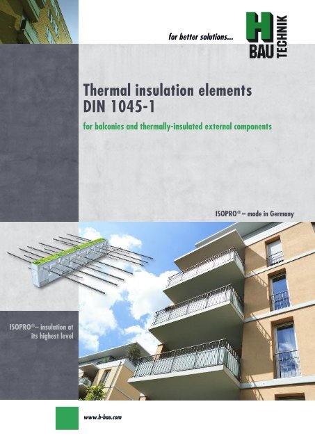
ISOPRO ® – insulation at<br />
its highest level<br />
Thermal insulation elements<br />
DIN 1045-1<br />
for balconies and thermally-insulated external components<br />
www.h-bau.com<br />
for better solutions...<br />
ISOPRO ® – made in Germany
H-Bau Technik GmbH<br />
Contact<br />
H-Bau<br />
Technik GmbH<br />
Head Office:<br />
Am Güterbahnhof 20<br />
79771 Klettgau<br />
Germany<br />
Tel. +49 (0) 77 42 / 92 15-20<br />
Fax +49 (0) 77 42 / 92 15-90<br />
eMail: export.klettgau@h-bau.de<br />
www.h-bau.com<br />
Production North-East:<br />
Brandenburger Allee<br />
14641 Nauen-Wachow<br />
Germany<br />
Tel. +49 (0) 332 39 / 775-20<br />
Fax +49 (0) 332 39 / 775-90<br />
eMail: export.berlin@h-bau.de<br />
Paul Rieger:<br />
Tel. +49 (0) 77 42 / 92 15-21<br />
Fax +49 (0) 77 42 / 92 15-93<br />
Mobil +49 (0) 171 / 864 72 61<br />
eMail: paul.rieger@h-bau.de<br />
Oliver Etzrodt<br />
Tel. +49 (0) 70 82 / 41 39 63<br />
Fax +49 (0) 70 82 / 79 33 00<br />
Mobil +49 (0) 171 / 864 72 60<br />
eMail: oliver.etzrodt@h-bau.de<br />
Rudolf Till<br />
Tel. +49 (0) 332 39 / 775-24<br />
Fax +49 (0) 332 39 / 775-90<br />
Mobil +49 (0) 172 / 993 70 50<br />
eMail: rudi.till@t-online.de
ISOPRO ®<br />
Balcony insulation elements<br />
Contents<br />
for better solutions...<br />
ISOPRO ® Thermal insulation elements<br />
General Overview of types 2-3<br />
Technical principles 4-6<br />
Building physics – Heat insulation 7<br />
Building physics – Fire protection 8<br />
Exposition class 9<br />
<strong>Type</strong> IP-<strong>IPT</strong> Examples 11<br />
Construction and dimensions 12-13<br />
Dimensioning table 14-15<br />
Special types 16-17<br />
On-site reinforcement and installation instructions 18-21<br />
Two-part elements 22-23<br />
Deflection and height offset 24-25<br />
Expansion joint spacing 26<br />
<strong>Type</strong> <strong>IPT</strong>-Corner Construction and dimensions/on-site reinforcement 27-29<br />
Dimensioning table 30<br />
<strong>Type</strong> IPH Technical principles 31<br />
<strong>Type</strong> IPE Technical principles 32<br />
Dimensioning table 33<br />
<strong>Type</strong> IPQ-IPQS Examples of shear force elements 34<br />
IPQZ Technical principles 35<br />
Construction and dimensions 36-37<br />
Dimensioning table 38<br />
On-site reinforcement 39-41<br />
<strong>Type</strong> IPQQ-IPQQS Construction and dimensions 42-43<br />
Dimensioning table 43<br />
On-site reinforcement 44-45<br />
Torque from eccentric connection 46<br />
<strong>Type</strong> <strong>IPT</strong>D Technical principles 47<br />
Construction and dimensions 48<br />
On-site reinforcement 49<br />
Dimensioning table 50-51<br />
<strong>Type</strong> IPA, IPF, IPO Technical principles 53<br />
<strong>Type</strong> IPA Construction and dimensional values 54<br />
On-site reinforcement and installation instructions 55<br />
<strong>Type</strong> IPF Construction and dimensional values 56<br />
On-site reinforcement and installation instructions 57<br />
<strong>Type</strong> IPO Construction and dimensional values 58<br />
On-site reinforcement and installation instructions 59<br />
<strong>Type</strong> IPS, IPW Technical principles 61<br />
<strong>Type</strong> IPS Construction and dimensional values 62<br />
On-site reinforcement and installation instructions 63<br />
<strong>Type</strong> IPW Construction and dimensional values 64<br />
On-site reinforcement and installation instructions 65<br />
Tender 66<br />
ISOPRO ® - insulation at its highest level<br />
1
2<br />
ISOPRO ®<br />
Overview of types<br />
www.h-bau.com<br />
ISOPRO ® type IP - page 12<br />
for freely-projecting balcony slabs.<br />
The element transfers negative bending moments<br />
and positive shear forces.<br />
ISOPRO ® type <strong>IPT</strong> - page 13<br />
for freely-projecting balcony slabs.<br />
The element transfers negative bending moments<br />
and positive shear forces.<br />
ISOPRO ® type <strong>IPT</strong>-Corner - page 27<br />
for freely-projecting external-corner balconies.<br />
The element transfers negative bending moments<br />
and positive shear forces.<br />
ISOPRO ® type IPQ - page 35<br />
for joint-supported slabs (e.g. balconies and<br />
loggia on supports).<br />
The element transfers positive shear forces.<br />
ISOPRO ® type IPQS - page 36<br />
for joint-supported slabs with selective force<br />
absorption.<br />
The element transfers positive shear forces.<br />
ISOPRO ® type IPQZ - page 36<br />
for joint-supported slabs with selective force<br />
absorption with zero stress.<br />
The element transfers positive shear forces.<br />
ISOPRO ® type IPQQ - page 42<br />
for joint-supported slabs.<br />
The element transfers positive and negative<br />
shear forces.<br />
ISOPRO ® type IPQQS - page 42<br />
for joint-supported slabs with selective force<br />
absorption.<br />
The element transfers positive and negative<br />
shear forces.<br />
Balkon Decke<br />
Balkon Decke<br />
Balkon Decke<br />
Balkon Decke<br />
Balkon Decke<br />
Balkon Decke<br />
Balkon Decke<br />
Balkon Decke
ISOPRO ®<br />
Overview of types<br />
ISOPRO ® type <strong>IPT</strong>D - page 47<br />
for re-entrant balcony slabs in the floor area.<br />
The element transfers positive and negative<br />
bending moments and shear forces.<br />
ISOPRO ® type IPH - page 31<br />
For selective absorption of horizontal forces in<br />
connection with cantilever slab or shear force<br />
connections.<br />
ISOPRO ® type IPE - page 32<br />
for selective absorption of horizontal forces<br />
and moments in conjunction with IP & <strong>IPT</strong> cantilever<br />
slab connections.<br />
ISOPRO ® type IPA - page 54<br />
for connection of fascias at storey floor level.<br />
The element is attached at selected points.<br />
ISOPRO ® type IPF - page 56<br />
for connection of projecting parapets at storey<br />
floor level.<br />
The element is attached at selected points.<br />
ISOPRO ® type IPO - page 58<br />
for connection of reinforced concrete consoles<br />
B<br />
at storey floor level.<br />
The element is attached at selected points.<br />
ISOPRO ® type IPS - page 62<br />
for connection of wall consoles and cantilever<br />
beams.<br />
The element transfers positive and negative<br />
shear forces.<br />
ISOPRO ® type IPW - page 64<br />
for connection of full-height wall panels.<br />
The element transfers bending moments and<br />
shear forces in both the vertical and horizontal<br />
direction.<br />
Konsole<br />
for better solutions...<br />
Balkon Decke<br />
Balkon Decke<br />
Balkon Decke<br />
Konsole<br />
Attika<br />
Brüstung<br />
B<br />
Decke<br />
Decke<br />
Decke<br />
Wandscheibe innen<br />
ISOPRO ® - insulation at its highest level<br />
3
4<br />
ISOPRO ®<br />
Technical principles<br />
The product<br />
ISOPRO ® is a thermally insulating,<br />
supporting, connection element between<br />
concrete construction components.<br />
Its excellent thermal insulation<br />
properties provide a reliable solution<br />
to the problems of building physics at<br />
the interface between external and internal<br />
construction elements.<br />
ISOPRO ® consists of an EPS insulating<br />
body 80 mm thick of the heat conduction<br />
group 035 together with a<br />
static rod framework that ensures effective<br />
transfer of the forces from BST<br />
500 in the area of the insulation and<br />
up to 100 mm to the side from BST<br />
500 NR.<br />
Elements made from high-performance<br />
specialty concrete or rods<br />
made from BST 500 NR are used in<br />
the compression zone.<br />
www.h-bau.com<br />
Features<br />
Approved and type-tested in accordance<br />
with DIN 1045-1<br />
Reduction of thermal bridges according<br />
to DIN 4108-2 and EnEV<br />
Avoids condensation and growth<br />
of mould<br />
Stainless steel construction provides<br />
corrosion protection<br />
Faster and more economical installation<br />
The consistently high quality standard<br />
of ISOPRO ® is maintained by<br />
continual in-house and third-party<br />
monitoring.<br />
Optimum absorption of shear<br />
forces and bending moments<br />
Application area<br />
Projecting balcony with ISOPRO ® type IP<br />
Supported balcony with ISOPRO ® type IPQ
ISOPRO ®<br />
Technical principles<br />
Installation locations for ISOPRO ® balcony insulation elements:<br />
for better solutions...<br />
ISOPRO ® in single-skin brickwork ISOPRO ® in single-skin brickwork with<br />
Thermal Insulation Bonding System<br />
ISOPRO ® in double-skin brickwork ISOPRO ® in double-skin brickwork with<br />
rear ventilation<br />
Order codes for ISOPRO ® balcony insulation elements:<br />
Order example 1:<br />
Freely-projecting balcony slab<br />
Slab thickness: h = 180 mm<br />
Concrete cover: c v = 35 mm<br />
m Ed = 31.6 kNm/m<br />
v Ed = 51.4 kN/m<br />
Fire protection requirement F90<br />
Order example 2:<br />
Supported balcony slab<br />
Slab thickness: h = 200 mm<br />
v Ed = 84,3 kN/m<br />
Fire protection requirement F90<br />
Additional identification for special element type IP:<br />
Downward curve in the wall ⇒ Var. l<br />
Upward curve in the wall ⇒ Var. ll<br />
Order example: IP 30 Var.l c v 35 h200<br />
IP 50 CV35 Q8 F90 h180<br />
<strong>Type</strong><br />
load bearing capacity<br />
concrete cover<br />
supplemented shear force<br />
fire protection class F90<br />
height of element<br />
IPQ 50 F90 h200<br />
<strong>Type</strong><br />
load bearing capacity<br />
fire protection class F90<br />
height of element<br />
Note:<br />
For types IPQ and IPQS no additional identification for the concrete covering c v is required.<br />
All of the special elements for types IP and <strong>IPT</strong> are shown on pages 16-17.<br />
Var. lll HV ⇐ ceiling offset upwards<br />
Var. lll UV ⇐ ceiling offset downwards<br />
ISOPRO ® 5<br />
- insulation at its highest level
6<br />
ISOPRO ®<br />
Component catalogue and test certificates<br />
Component catalogue ISOPRO ® elements<br />
Reinforcing steel: BSt 500 S<br />
Stainless steel: BSt 500 NR in accordance with general building authority approval Material<br />
No. 1.4571 or 1.4362<br />
Compression bearing: Pressure elements made from high tensile special concrete;<br />
BSt 500 NR in accordance with general building authority approval<br />
Insulation body: Rigid polystyrene foam of heat conduction group 035<br />
Fire protection slabs: Fibre-cement slab from construction material class A1<br />
Connecting structural components<br />
Concrete: Standard concrete according to DIN 1045-2 or DIN EN 206-1 with a dry bulk<br />
density of 2000 kg/m 3 to 2600 kg/m 3 (light concrete is not permitted)<br />
Reinforcing steel: BSt 500 M and BSt 500 S<br />
Test certificates<br />
Approvals: DIBt Berlin<br />
General building authority approval<br />
ISOPRO type IP Z-15.7-244<br />
ISOPRO type <strong>IPT</strong> Z-15.7-243<br />
type testing: State Office for Construction Engineering, Tübingen<br />
Test Report (type testing)<br />
ISOPRO type IP Prüf-Nr. 06/2<br />
ISOPRO type <strong>IPT</strong> Prüf-Nr. 08/5<br />
ISOPRO type IPQ Prüf-Nr. 08/6<br />
www.h-bau.com<br />
Minimum strength of concrete for external structural components:<br />
≥ C25/30 and dependent on the exposition classes according to DIN 1045-1<br />
Minimum strength of concrete for internal structural components:<br />
≥ C20/25 and dependent on the exposition classes according to DIN 1045-1
ISOPRO ®<br />
Building physics – Heat insulation<br />
Thermal bridge<br />
In the construction of buildings, unconsidered<br />
thermal bridges are a hidden<br />
risk. Thermal bridges are defined<br />
as locations in parts of a building in<br />
which heat transfer to the outside occurs<br />
more quickly than in other parts<br />
of the building.<br />
There is a difference between geometrical<br />
thermal bridges, in which, for<br />
the heat dissipation from the internal<br />
surface, there is an adjacent, larger,<br />
external surface (e.g. external corners<br />
of the building), and constructed thermal<br />
bridges, which create thermal<br />
bridges by the use of fixtures or materials<br />
with high heat conductivity or<br />
lack of thermal insulation. One example<br />
of constructive thermal bridges<br />
is reinforced concrete elements which<br />
penetrate external walls. At low outside<br />
temperatures, this increased heat<br />
flow leads to lower temperatures at<br />
the surface of the room wall. Problems<br />
of decreasing temperatures result<br />
from surface contact with the air<br />
in the room and its water retention capacity.<br />
Air humidity<br />
Air humidity (also air moisture) is defined<br />
as the proportion of water<br />
vapour mixed with gas (in this case in<br />
the room). The best known measure<br />
of humidity is the relative humidity,<br />
given as a percentage, which relates<br />
to the proportion of<br />
water vapour content in the air to the<br />
maximum possible content at any<br />
time. At lower temperatures the water<br />
retention capacity is lower than at<br />
higher temperatures, so that one<br />
cubic metre of air at 10ºC can absorb<br />
9.41 g of water.<br />
The same volume of air at 30ºC can<br />
absorb up to 30.38 g of water. This is<br />
known as saturation concentration.<br />
Due to fluctuating temperatures, for<br />
the same water concentration the relative<br />
humidity in the room also<br />
changes. Air, which is being cooled<br />
at the surface close to the thermal<br />
bridge, produces an increase in relative<br />
humidity until it reaches saturation<br />
concentration.<br />
Dew point temperature<br />
The temperature at which the water<br />
volume in the air is sufficient to cause<br />
saturation (relative humidity of 100%)<br />
is known as the dew point temperature,<br />
since a further decrease in temperature<br />
will cause excess humidity to<br />
be released from the air as condensate.<br />
This condensate attaches itself to<br />
the surface of the wall.<br />
Therefore, the higher the temperature<br />
and relative humidity levels in the<br />
dew point temperature [°C]<br />
20<br />
18<br />
16<br />
14<br />
12.6<br />
12<br />
10<br />
9.3<br />
8<br />
no risk *<br />
for better solutions...<br />
room are, the higher is the condensation<br />
point temperature and with it the<br />
increased risk of water condensation<br />
on the colder parts of the building surfaces.<br />
The assumed room climate is<br />
20ºC and 50% relative humidity. For<br />
these conditions the dew point temperature<br />
is 9.3ºC.<br />
The minimum heat insulation<br />
The hazard threat comes not only<br />
from humidity-related effects on construction<br />
elements and the associated<br />
damage to the building, but, more<br />
importantly, also from the health hazard<br />
due to mildew formation in these<br />
areas. The formation of mildew does<br />
not only start at the point when water<br />
condensation occurs, but already at<br />
the point when the surface temperature<br />
at the wall produces 80% relative<br />
air humidity. For normal climatic conditions<br />
in a room, the non-critical surface<br />
temperature is 12.6ºC. When<br />
this surface temperature is reached<br />
there is no further hazard risk.<br />
air temperature 22°C<br />
air temperature 20°C<br />
Relative humidity [%]<br />
air temperature 18°C<br />
* No risk of mildew formation from12.6ºC<br />
(DIN 4108-2 : 2001-03)<br />
6<br />
40 45 50 55 60 65 70 75 80 85 90<br />
Dependence of the dew point temperature on relative humidity and air temperature<br />
ISOPRO ® - insulation at its highest level<br />
7
8<br />
ISOPRO ®<br />
Building physics – Fire protection DIN 4109<br />
Fire-resistance class F 30<br />
All ISOPRO ® elements are categorised as fire protection class F30. The requirements to be met for the complete construction<br />
are illustrated in the following diagrams:<br />
F30 - wall area construction F30 - door area construction<br />
mineral-based mineral-based plaster plaster<br />
screeding / screeding plastering / plastering<br />
ISOPRO element ISOPRO element<br />
screeding / screeding plastering / plastering<br />
ISOPRO element ISOPRO element<br />
mineral-based mineral-based plaster plaster mineral-based mineral-based plaster plaster<br />
Fire-resistance class F 90<br />
All ISOPRO ® elements are also supplied to fire-resistance class F90, meeting the technical requirements for fire protection<br />
of balconies etc.<br />
The designation F90 is added to the element identification e.g. ISOPRO ® <strong>IPT</strong> 55 cv 30 F90.<br />
A1 material<br />
non-flammable<br />
The ISOPRO ® elements are fitted with fire protection plates attached to the top side and the under side.<br />
The construction can be seen in the sketch of the system below.<br />
detail 1<br />
detail 1<br />
A1 material<br />
non-flammable<br />
It is self-evident that to meet the requirements of the fire-resistance class F90, all other adjacent construction elements<br />
must also satisfy these requirements. For constructions with selected-point connections it is necessary to ensure that the<br />
intermediate insulation used also meets the fire-resistance requirements.<br />
www.h-bau.com<br />
100<br />
15<br />
15<br />
8<br />
F90 fire fire protection slab<br />
F90 fire fire protection slab
ISOPRO ®<br />
Exposition classes<br />
Exposition classes and concrete covering<br />
Reinforcement corrosion Minimum concrete<br />
strength class<br />
XC3 high humidity, outside<br />
construction elements,<br />
damp rooms<br />
XC4 alternating wet and dry,<br />
outside construction elements<br />
exposed to rain<br />
XD1 high humidity, area of<br />
spray water from road<br />
surface<br />
XS1 salt-laden air, outside<br />
construction elements<br />
near coasts<br />
Concrete attack Minimum concrete<br />
strength class<br />
XF1 high water saturation<br />
with no condensation<br />
source, outside construction<br />
elements<br />
Depth of concrete<br />
covering c nom<br />
Red. depth of concrete<br />
covering c v *<br />
C 20/25 c nom = 35 mm c v = 30 mm<br />
C 25/30 c nom = 40 mm c v = 35 mm<br />
C 30/37 c nom = 55 mm c v = 50 mm<br />
C 30/37 c nom = 55 mm c v = 50 mm<br />
C 25/30<br />
Concrete covering<br />
c v = degree of<br />
reinforcement corrosion<br />
* c v = a reduction of 5mm according to DIN 1045-1, 6.3 is taken into account<br />
DIN 1045-1 Concrete covering:<br />
for better solutions...<br />
Table for concrete covering<br />
This table for concrete covering is<br />
extracted from Tables 3 + 4 in DIN<br />
1045-1, 6.3<br />
The recommendations for external<br />
balconies are:<br />
in-situ concrete balconies, prefabricated<br />
balconies and filigree<br />
slabs with in-situ concrete covering<br />
and permanent sealing on<br />
the top surface:<br />
- concrete class C 25/30<br />
- exposition class XC4 with c v 30<br />
in-situ concrete balconies, prefabricated<br />
balconies and filigree<br />
slabs with in-situ concrete covering<br />
without permanent sealing:<br />
- concrete class C 25/30<br />
- exposition class XC4 with c v 35<br />
For constructions in accordance with DIN 1045-1 the most binding requirement is the issue of concrete covering (exposition<br />
class).<br />
The following concrete coverings (c v ) are frequently encountered:<br />
c v = 30mm<br />
c v = 35mm<br />
c v = 40mm<br />
c v = 50mm (second layer for c v = 30mm and c v = 35mm)<br />
Example: IP 12/10 c v 30 h = 180 mm<br />
Always include the element height!<br />
ISOPRO ® - insulation at its highest level<br />
9
10<br />
ISOPRO ®<br />
Dimensioning program ISOPRO ® DESIGN<br />
ISOPRO ® DESIGN dimensioning program<br />
With ISOPRO ® DESIGN we are passing on our many years of experience in the dimensioning of our ISOPRO ® thermal<br />
insulation elements for the most popular balcony systems.<br />
You can select from the popular balcony systems, e.g. cantilever balcony, supported balcony, loggia, internal corner balcony<br />
and external corner balcony, or using free inputs of known dimensional values work out the loading. After inputting<br />
the geometrical data and the effective loads, the relevant ISOPRO ® elements can be selected.<br />
The classification and the geometrical circumstances<br />
of the ISOPRO ® elements can<br />
be checked for feasibility in section and<br />
plan view and, if required, printed out as a<br />
formwork drawing or exported as a dxf file<br />
for further processing.<br />
Features<br />
all popular balcony systems can be selected<br />
installation languages German, English<br />
and Polish<br />
Dimensioning in accordance with German,<br />
Swiss or Polish standards (DIN,<br />
SIA, Eurocode)<br />
Dimensioning using FEM module<br />
Report output with verification<br />
CAD export<br />
www.h-bau.com<br />
ISOPRO ® DESIGN on CD or as free download at:<br />
Tel.: +49 (0) 77 42 / 92 15-20<br />
Fax: +49 (0) 77 42 / 92 15-90<br />
eMail: info@h-bau.de<br />
Internet: www.h-bau.com
IP / <strong>IPT</strong> 1st position<br />
ISOPRO ® <strong>Type</strong> IP / <strong>IPT</strong><br />
Examples<br />
IP / <strong>IPT</strong> 2nd position<br />
IP / <strong>IPT</strong><br />
IP / <strong>IPT</strong><br />
IP / <strong>IPT</strong><br />
IP / <strong>IPT</strong><br />
IP / <strong>IPT</strong> IP / <strong>IPT</strong><br />
IP / <strong>IPT</strong> IP / IP <strong>IPT</strong> / <strong>IPT</strong> IP / <strong>IPT</strong><br />
Freely-projecting balcony<br />
Side-separated internal corner balcony Internal corner balcony<br />
Internal corner balcony/loggia overlying on 3 sides,<br />
partially projecting<br />
<strong>IPT</strong> Corner IP / <strong>IPT</strong><br />
IP / <strong>IPT</strong><br />
2nd position<br />
for better solutions...<br />
IP / <strong>IPT</strong><br />
IP / <strong>IPT</strong><br />
IP / <strong>IPT</strong><br />
IP / <strong>IPT</strong><br />
IP / <strong>IPT</strong><br />
IP / <strong>IPT</strong><br />
IP / <strong>IPT</strong><br />
IP / <strong>IPT</strong><br />
IP / <strong>IPT</strong><br />
IP / <strong>IPT</strong><br />
IP / <strong>IPT</strong> 1st position<br />
1st position<br />
IP / <strong>IPT</strong> IP / IP <strong>IPT</strong>/ <strong>IPT</strong> IP / <strong>IPT</strong> 1st positionIP<br />
/ <strong>IPT</strong><br />
IP / <strong>IPT</strong> IP / <strong>IPT</strong><br />
IP / <strong>IPT</strong><br />
1st position<br />
1st position<br />
IP / <strong>IPT</strong> 2nd position<br />
IP / <strong>IPT</strong> 2nd position<br />
IP / <strong>IPT</strong> 1st position<br />
IP / <strong>IPT</strong> 1st position<br />
IP / <strong>IPT</strong> 1st position<br />
IP / <strong>IPT</strong> 2nd position<br />
IP / <strong>IPT</strong> 2nd position<br />
IP / <strong>IPT</strong> 2nd position<br />
IP / <strong>IPT</strong> 2nd position<br />
IP / <strong>IPT</strong> 1st position<br />
IP / <strong>IPT</strong> 2nd position<br />
IP / <strong>IPT</strong> 2nd position<br />
IP / <strong>IPT</strong><br />
IP / <strong>IPT</strong><br />
<strong>IPT</strong> Corner<br />
<strong>IPT</strong> Corner<br />
IP / <strong>IPT</strong> <strong>IPT</strong> Corner<br />
IP / <strong>IPT</strong> <strong>IPT</strong> Corner IP / <strong>IPT</strong> <strong>IPT</strong> Corner<br />
<strong>IPT</strong> Corner IP / <strong>IPT</strong><br />
IP / <strong>IPT</strong><br />
2nd position<br />
External corner balcony<br />
IP / <strong>IPT</strong><br />
11<br />
ISOPRO ® - insulation at its highest level<br />
<strong>IPT</strong> Corner IP / <strong>IPT</strong><br />
IP / <strong>IPT</strong><br />
2nd position<br />
<strong>IPT</strong> Corner IP / <strong>IPT</strong><br />
IP / <strong>IPT</strong><br />
2nd position<br />
<strong>IPT</strong> Corner IP / <strong>IPT</strong><br />
IP / <strong>IPT</strong><br />
2nd position
12<br />
ISOPRO ® <strong>Type</strong> IP<br />
Construction and dimensions<br />
Section IP<br />
160 - 250<br />
Section IP - X<br />
160 - 250<br />
balcony side<br />
balcony side<br />
Configuration of the elements<br />
1000<br />
Dimensions type IP [length in mm]<br />
L ZB<br />
L ZB<br />
Top view<br />
L Q<br />
L Q<br />
80<br />
80<br />
80<br />
<strong>Type</strong> Length of element [mm] Tension rods Shear force rods Compression support<br />
L Q<br />
L ZD<br />
L ZD<br />
slab side<br />
slab side<br />
IP 10 1000 7 Ø 6 4 Ø 6 4<br />
IP 20 1000 7 Ø 8 4 Ø 6 4<br />
IP 25 1000 8 Ø 8 4 Ø 8 4<br />
IP 30 1000 4 Ø 8 + 4 Ø 10 4 Ø 8 6<br />
IP 40 1000 8 Ø 10 4 Ø 8 6<br />
IP 50 1000 10 Ø 10 4 Ø 8 8<br />
<strong>Type</strong><br />
Tension rods<br />
LZB LZD Shear force rods<br />
LQ LQ8 Supplemental shear force<br />
LQ10 LQ12 IP 10 370 430 250 615 - -<br />
IP 20 480 560 250 615 - -<br />
IP 25 480 560 280 615 615 745<br />
IP 30 590 690 280 615 615 745<br />
IP 40 590 690 280 615 615 745<br />
IP 50 590 690 280 615 615 745<br />
Expansion joint spacings for ISOPRO ® type IP can be found on page 26.<br />
www.h-bau.com<br />
Element classification<br />
see type test IP<br />
<strong>Type</strong> test<br />
Prüf-Nr. 06/2<br />
Approval<br />
Ap-No. Z-15.7-244
ISOPRO ® <strong>Type</strong> <strong>IPT</strong><br />
Construction and dimensions<br />
Section <strong>IPT</strong><br />
160 - 250<br />
160 - 250<br />
1000<br />
L ZB<br />
L ZB<br />
L Q<br />
L Q<br />
L D<br />
L D<br />
80<br />
balcony side slab side<br />
Section <strong>IPT</strong> - X<br />
Configuration of the elements<br />
80<br />
80<br />
balcony side slab side<br />
Dimensions type <strong>IPT</strong> [length in mm]<br />
Top view<br />
<strong>Type</strong> Length of element [mm] Tension rods Shear force rods Compression rods<br />
Tension rods Shear force rods Compr. rods Supplemental shear force<br />
<strong>Type</strong><br />
LZB LZD LQ LD LQ8 LQ10 LQ12 <strong>IPT</strong> 55 710 810 210 165 400 400 490<br />
<strong>IPT</strong> 60 590 690 210 165 400 400 490<br />
<strong>IPT</strong> 70 710 810 210 165 400 400 490<br />
<strong>IPT</strong> 80 710 810 210 165 400 400 490<br />
<strong>IPT</strong> 100 710 830 210 200 400 400 490<br />
80<br />
<strong>IPT</strong> 55 500 + 500 6 Ø 10 + 4 Ø12 4 Ø 8 6x2 Ø 10 + 4x2 Ø 12<br />
<strong>IPT</strong> 60 500 + 500 10 Ø 12 4 Ø 8 10x2 Ø 12<br />
<strong>IPT</strong> 70 500 + 500 10 Ø 12 4 Ø 8 7x2 Ø 14 + 3x2 Ø 12<br />
<strong>IPT</strong> 80 500 + 500 10 Ø 12 4 Ø 8 10x2 Ø 14<br />
<strong>IPT</strong> 100 500 + 500 10 Ø 14 4 Ø 8 10x2 Ø 14<br />
Expansion joint spacings for ISOPRO ® type <strong>IPT</strong> can be found on page 26.<br />
L D<br />
L D<br />
L Q<br />
L ZD<br />
L ZD<br />
for better solutions...<br />
Element classification<br />
see type test IP<br />
<strong>Type</strong> test<br />
Prüf-Nr. 08/5<br />
Approval<br />
Ap-No. Z-15.7-243<br />
IP / <strong>IPT</strong><br />
13<br />
ISOPRO ® - insulation at its highest level
14<br />
ISOPRO ®<br />
Dimensioning table for concrete ≥ C20/25<br />
Element height [mm]<br />
dependent on c v [mm]<br />
Dimensional values of the absorbable moments m Rd [kNm/m]<br />
30 35 40 45 50 IP 10 IP 20 IP 25 IP 30 IP 40<br />
- - - - 160 7.0 12.2 13.8 17.7 20.4<br />
- - - 160 - 7.4 13.0 14.6 18.8 21.7<br />
- - 160 - 170 7.8 13.8 15.5 19.9 23.0<br />
- 160 - 170 - 8.3 14.5 16.3 21.1 24.3<br />
160 - 170 - 180 8.7 15.3 17.2 22.2 25.5<br />
- 170 - 180 - 9.1 16.1 18.1 23.3 26.8<br />
170 - 180 - 190 9.6 16.8 18.9 24.4 28.1<br />
- 180 - 190 - 10.0 17.6 19.8 25.5 29.4<br />
180 - 190 - 200 10.4 18.4 20.6 26.7 30.7<br />
- 190 - 200 - 10.8 19.1 21.5 27.8 32.0<br />
190 - 200 - 210 11.3 19.9 22.4 28.9 33.3<br />
- 200 - 210 - 11.7 20.7 23.2 30.0 34.6<br />
200 - 210 - 220 12.1 21.4 24.1 31.1 35.9<br />
- 210 - 220 - 12.6 22.2 24.9 32.3 37.2<br />
210 - 220 - 230 13.0 22.9 25.8 33.4 38.4<br />
- 220 - 230 - 13.4 23.7 26.7 34.5 39.7<br />
220 - 230 - 240 13.9 24.5 27.5 35.6 41.0<br />
- 230 - 240 - 14.3 25.2 28.4 36.7 42.3<br />
230 - 240 - 250 14.7 26.0 29.2 37.9 43.6<br />
- 240 - 250 - 15.1 26.8 30.1 39.0 44.9<br />
240 - 250 - - 15.6 27.5 31.0 40.1 46.2<br />
- 250 - - - 16.0 28.3 31.8 41.2 47.5<br />
250 - - - - 16.4 29.1 32.7 42.3 48.8<br />
Dimensional values of the absorbable shear forces v Rd [kN/m]<br />
h = 160 - 250 [mm] 27.5 41.5<br />
<strong>Type</strong>s with supplemented shear force load bearing capacity<br />
<strong>Type</strong> IP 10 Q... IP 20 Q... IP 25 Q... IP 30 Q... IP 40 Q...<br />
Dimensional values of the absorbable shear forces v Rd [kN/m]<br />
Q8 (2Ø8/2Ø10) h ≥ 170mm 61.8* 79.2<br />
Q10 (4Ø10) h ≥ 170mm 96.6<br />
Q12 (4Ø12) h ≥ 180mm 139.1<br />
* (4 Ø8) h ≥ 160mm<br />
<strong>Type</strong>s with positive and negative shear force absorption<br />
Dimensional values of the absorbable shear forces v Rd [kN/m]<br />
<strong>Type</strong> IP 10 IP 20 IP 25 IP 30 IP 40<br />
Q8X (4Ø8/2Ø10) + 61.8 / - 48.8<br />
Q10X (4Ø10/2Ø12) + 96.6 / - 69.6<br />
Q12X (4Ø12/2Ø12) + 139.1 / - 69.6<br />
www.h-bau.com
ISOPRO ®<br />
Dimensioning table for concrete ≥ C20/25<br />
Dimensional values of the absorbable moments m Rd [kNm/m]<br />
IP 50 <strong>IPT</strong> 55 <strong>IPT</strong> 60 <strong>IPT</strong> 70 <strong>IPT</strong> 80 <strong>IPT</strong> 100<br />
27.0 28.3 31.9 35.2 36.8 43.9<br />
28.7 30.1 33.9 37.5 39.1 46.8<br />
30.4 31.9 36.0 39.7 41.5 49.7<br />
32.1 33.7 38.0 42.0 43.9 52.6<br />
33.8 35.6 40.1 44.3 46.3 55.5<br />
35.5 37.4 42.1 46.6 48.6 58.4<br />
37.2 39.2 44.2 48.9 51.0 61.3<br />
38.9 41.0 46.2 51.1 53.4 64.2<br />
40.6 42.8 48.2 53.4 55.8 67.1<br />
42.3 44.6 50.3 55.7 58.2 69.9<br />
44.1 46.4 52.3 58.0 60.6 72.8<br />
45.8 48.2 54.4 60.3 62.9 75.7<br />
47.5 50.1 56.4 62.5 65.3 78.6<br />
49.2 51.9 58.5 64.8 67.7 81.5<br />
50.9 53.7 60.5 67.1 70.1 84.4<br />
52.6 55.5 62.5 69.4 72.5 87.3<br />
54.3 57.3 64.6 71.7 74.9 90.2<br />
56.0 59.1 66.6 74.0 77.3 93.1<br />
57.7 60.9 68.7 76.2 79.6 96.0<br />
59.4 62.8 70.7 78.5 82.0 98.8<br />
61.1 64.6 72.8 80.8 84.4 101.7<br />
62.8 66.4 74.8 83.1 86.8 104.6<br />
64.5 68.2 76.9 85.4 89.2 107.5<br />
Dimensional values of the absorbable shear forces v Rd [kN/m]<br />
41.5<br />
IP 50 Q... <strong>IPT</strong> 55 Q... <strong>IPT</strong> 60 Q... <strong>IPT</strong> 70 Q... <strong>IPT</strong> 80 Q... <strong>IPT</strong> 100 Q...<br />
Dimensional values of the absorbable shear forces v Rd [kN/m]<br />
79.2<br />
96.6<br />
139.1<br />
Dimensional values of the absorbable shear forces v Rd [kN/m]<br />
IP 50 <strong>IPT</strong> 55 <strong>IPT</strong> 60 <strong>IPT</strong> 70 <strong>IPT</strong> 80 <strong>IPT</strong> 100<br />
+ 61.8 / - 48.8<br />
+ 96.6 / - 69.6<br />
+ 139.1 / - 69.6<br />
for better solutions...<br />
IP / <strong>IPT</strong><br />
15<br />
ISOPRO ® - insulation at its highest level
16<br />
ISOPRO ®<br />
Special types Valid for type series IP and <strong>IPT</strong> (analogously)<br />
Connection to a floor slab with a “small” step-up offset<br />
balcony<br />
wall<br />
slab<br />
balcony<br />
�<br />
For a step-up offset of less than 80 mm a standard element<br />
can also be used.<br />
� slab<br />
In balcony this case a stirrup reinforcement � wall with an upper leg<br />
balcony<br />
�<br />
length ≥ ls is required to deflect the tensile force towards<br />
the floor.<br />
�<br />
Dimensioning of the stirrup reinforcement � for cantilever<br />
wall<br />
effect and shear force on the � balcony slab.<br />
��<br />
balcony � wall<br />
balcony<br />
balcony<br />
balcony<br />
h ≤ 80<br />
h ≤ 80<br />
Connection to a vertical wall – connection downwards<br />
balcony<br />
�<br />
wall<br />
wall<br />
Connection to a vertical wall – �connection<br />
upwards<br />
balcony wall<br />
�<br />
balcony wall<br />
h ≤ 80<br />
The ISOPRO<br />
�<br />
® tension rods correspond to the required<br />
�<br />
overlap length ls in accordance with DIN 1045-1.<br />
See pages 18-21 for connection reinforcement to the<br />
balcony side.<br />
�<br />
balcony wall<br />
�<br />
≥ 220<br />
�<br />
�<br />
≥ 220<br />
�<br />
�<br />
�<br />
slab<br />
slab<br />
The ISOPRO<br />
slab<br />
balcony<br />
�<br />
�<br />
� slab<br />
® tension rods correspond to the required<br />
overlap length ls in accordance with DIN 1045-1.<br />
See pages 18-21 for connection reinforcement to the<br />
balcony side.<br />
www.h-bau.com<br />
�<br />
�<br />
�<br />
�<br />
�<br />
� upper reinforcement of steel bars or mesh<br />
� closed stirrup<br />
� lower reinforcement of steel bars or mesh<br />
� upper reinforcement of steel bars or mesh<br />
For connection reinforcement on the balcony side see<br />
� closed stirrup<br />
pages 18-21. � upper reinforcement of steel bars or mesh<br />
The necessary shear reinforcement in the overlap area<br />
must be proved in accordance with DIN 1045-1.<br />
Recommended joist width: � closed at least stirrup 200 mm.<br />
� lower reinforcement of steel bars or mesh<br />
Var. I<br />
insert stirrup<br />
�<br />
�<br />
insert stirrup<br />
� insert stirrup<br />
�<br />
� insert stirrup<br />
� insert stirrup<br />
� insert stirrup<br />
� upper reinforcement of steel bars or mesh<br />
� closed stirrup<br />
� reinforcement<br />
lower reinforcement of steel bars or mesh<br />
� reinforcement<br />
� reinforcement<br />
� reinforcement<br />
The necessary shear reinforcement in the overlap area<br />
must be proved in accordance with DIN 1045-1.<br />
The minimum wall thickness is dependent on the type.<br />
Var. II<br />
� reinforcement<br />
The necessary shear reinforcement in the overlap area<br />
� upper reinforcement of steel bars or mesh<br />
must be proved � lower in accordance reinforcement with of steel DIN bars 1045-1. or mesh<br />
The minimum wall thickness is dependent on the type.<br />
� closed stirrup<br />
� upper reinforcement of steel bars or mesh<br />
� angled reinforcement<br />
� closed stirrup<br />
� reinforcement
�<br />
balcony wall<br />
ISOPRO ®<br />
Special types Valid for type series � IP and <strong>IPT</strong> (analogously)<br />
�<br />
balcony wall<br />
Connection to a floor slab with a step-up offset<br />
balcony<br />
≥ 220<br />
�<br />
balcony<br />
�<br />
Dimensioning of the stirrup reinforcement for cantilever<br />
�<br />
moment and shear force for the balcony slab.<br />
The <strong>ISOPRO®</strong> tension rods correspond to the required<br />
overlap length ls in accordance with DIN 1045-1.<br />
balcony<br />
On-site connection reinforcement see pages 18-21.<br />
Connection to a floor slab with step-down offset �<br />
�<br />
balcony<br />
≥ 220<br />
�<br />
�<br />
�<br />
≥ 220<br />
�<br />
≥ 220<br />
�<br />
slab<br />
slab<br />
Dimensioning of the stirrup reinforcement for cantilever<br />
moment and shear force for the balcony slab.<br />
The <strong>ISOPRO®</strong> tension rods correspond to the required<br />
overlap length ls in accordance with DIN 1045-1.<br />
On-site connection reinforcement see pages 18-21.<br />
�<br />
Var. III HV<br />
slab<br />
slab<br />
�<br />
�<br />
�<br />
Var. III UV<br />
For further solutions please contact our applications engineering department.<br />
Tel.: +49 (0) 77 42 / 92 15-70<br />
Fax: +49 (0) 77 42 / 92 15-96<br />
�<br />
�<br />
� upper reinforcement of steel bars or mesh<br />
�<br />
� closed stirrup<br />
� reinforcement<br />
� lower reinforcement of steel bars or mesh<br />
� closed stirrup<br />
The required shear reinforcement in the overlap area<br />
must be proved in accordance with DIN 1045-1.<br />
� angled reinforcement<br />
Recommended minimum beam width: at least 220 mm<br />
closed stirrup<br />
closed stirrup<br />
� insert sti<br />
� upper reinforcement of steel bars or mesh<br />
�<br />
� insert stirrup<br />
� lower reinforcement of steel bars or mesh<br />
� upper reinforcement of steel bars or mesh<br />
� angled reinforcement<br />
� insert stirrup<br />
� lower reinforcement of steel bars or mesh<br />
� upper reinforcement of steel bars or mesh<br />
� insert stirrup<br />
for better solutions...<br />
� reinforcement<br />
� lower reinforcement of steel bars or mesh<br />
The required shear reinforcement in the overlap area<br />
must be proved in accordance with DIN 1045-1.<br />
Constructive angled reinforcement item 3.<br />
Recommended minimum beam width: at least 220 mm<br />
�<br />
IP / <strong>IPT</strong><br />
17<br />
ISOPRO ® - insulation at its highest level
alcony slab<br />
ny slab<br />
�<br />
balcony slab<br />
ISOPRO ® ny <strong>Type</strong> IP slab<br />
balcony slab<br />
� �<br />
ny slab<br />
�<br />
balcony slab<br />
� �<br />
balcony slab<br />
A<br />
�<br />
� �<br />
�<br />
� �<br />
concrete ≥ 25/30 concrete ≥ 20/25<br />
ny slab<br />
18<br />
ISOPRO ® <strong>Type</strong> IP<br />
On-site reinforcement and installation instructions<br />
�<br />
A<br />
ISOPRO ® type IP with on-site mesh support<br />
The mesh support replaces the suspension reinforcement.<br />
It should be installed at a distance of ≤ 100 mm from the<br />
insulation and raised up until it is immediately below the<br />
tension reinforcement. The diameter of the diagonals must<br />
be at least 5 mm. The transverse force rod can be positioned<br />
above or below the mesh support.<br />
www.h-bau.com<br />
ISOPRO ® <strong>Type</strong> IP<br />
ny slab<br />
�<br />
A<br />
�<br />
te ≥ 25/30 concrete ≥ 20/25<br />
A<br />
�<br />
�<br />
�<br />
�<br />
�<br />
Section A - A<br />
Section A - integral A suspension reinforcement<br />
integral suspension � reinforcement<br />
�<br />
�<br />
�<br />
ISOPRO tension rods<br />
� insert edging according to DIN<br />
� � lower reinforcement<br />
� ISOPRO transverse force rods ISOPRO compression support � distribution rods Ø 8<br />
� lower reinforcement<br />
ISOPRO transverse force rods<br />
Installation instructions<br />
Lay the lower reinforcement � for the floor and balcony<br />
slab.<br />
Install ISOPRO ® IP and align. The direction of alignment<br />
(arrow symbol on top of element) must be followed.<br />
Insert the balcony-side edging � in accordance with<br />
DIN 1045-1 and connect to the ISOPRO ® tension rods.<br />
The ISOPRO ® tension rods and the support reinforcement<br />
are at the same level. If required. the binder on<br />
the tension rod level can be cut through.<br />
Lay the distribution rods. one Ø 8 top and bottom item<br />
�.<br />
In the case of indirect support, lay the floor-side edging<br />
� according to DIN 1045-1 and distribution rods �<br />
Ø 8.<br />
Insert the upper slab reinforcement � and bind together<br />
with the ISOPRO ® tension rods. The ISOPRO ®<br />
tension rods and the support reinforcement are at the<br />
same level.<br />
It is necessary when concreting to fill and pack uniformly<br />
on both sides in order to prevent movement of<br />
the ISOPRO ® elements<br />
balcony<br />
Mesh support<br />
ISOPRO tension rods<br />
ISOPRO compression support<br />
100<br />
� upper reinforcement<br />
� upper reinforcement<br />
� insert edging according to DIN<br />
� distribution rods Ø 8<br />
slab
ISOPRO ® <strong>Type</strong> IP<br />
On-site connection reinforcement<br />
On-site connection reinforcement for ISOPRO ® type IP<br />
<strong>Type</strong><br />
as,erf *<br />
[cm²/m]<br />
for better solutions...<br />
Recommendation for on-site connection reinforcement<br />
Concrete reinforcing steel<br />
rod BSt 500 S<br />
Concrete steel mesh<br />
BSt 500 M<br />
ISOPRO ® elements are supplied as standard from the factory with the required balcony-side suspension reinforcement.<br />
On the end-face side of the slabs to be connected, distribution rods of at least 2 Ø 8 are to be arranged on-site.<br />
In the case of indirect support of the elements it should be noted:<br />
A suspension reinforcement is required on the floor side that is dimensioned for V Rd . Distribution rods of at least 2 Ø 8<br />
are to be arranged on the end-face side of the slabs.<br />
The required steel cross-section for the suspension reinforcement per metre can be taken from the table:<br />
Concrete steel mesh<br />
+ reinforcing steel rod<br />
IP 10 1.98 Ø 8 / 200 Q257A / R257A -<br />
IP 20 3.52 Ø 10 / 170 Q424A / R424A Q188A + Ø 6/150<br />
IP 25 4.02 Ø 10 / 150 Q424A / R424A Q257A + Ø 6/150<br />
IP 30 5.15 Ø 10 / 110 Q524A / R524A Q188A + Ø 8/150<br />
IP 40 6.28 Ø 10 / 100 Q636A Q335A + Ø 8/150<br />
IP 50 7.85 Ø 12 / 100 - Q 524A + Ø 8/150<br />
* The required connection reinforcement A s,erf applies to fully-loaded ISOPRO ® elements. For lower loading, these can<br />
be reduced correspondingly.<br />
Note:<br />
For proof of the shear force load bearing capacity of the slabs without web reinforcement. DIN 1045-1. Section 10.3.3<br />
applies. For proof of the shear force load bearing capacity of the slabs with web reinforcement DIN 1045-1. Section<br />
10.3.4 applies. The maximum shear force transferable across the joint is limited to 0.3 · V Rd.max .<br />
Suspension reinforcement for ISOPRO ® type IP<br />
<strong>Type</strong> Standard Q8 Q10 Q12<br />
IP 10 Q...<br />
IP 20 Q...<br />
IP 25 Q...<br />
IP 30 Q...<br />
IP 40 Q...<br />
IP 50 Q...<br />
a s,erf [cm²/m] 0.63 1.42 2.22 3.20<br />
selected 4 Ø 6 4 Ø 8 4 Ø 10 4 Ø 12<br />
a s,erf [cm²/m] 0.63 1.42 2.22 3.20<br />
selected 4 Ø 6 4 Ø 8 4 Ø 10 4 Ø 12<br />
a s,erf [cm²/m] 0.95 1.82 2.22 3.20<br />
selected 4 Ø 6 4 Ø 8 4 Ø 10 4 Ø 12<br />
a s,erf [cm²/m] 0.95 1.82 2.22 3.20<br />
selected 4 Ø 6 4 Ø 8 4 Ø 10 4 Ø 12<br />
a s,erf [cm²/m] 0.95 1.82 2.22 3.20<br />
selected 4 Ø 6 4 Ø 8 4 Ø 10 4 Ø 12<br />
a s,erf [cm²/m] 0.95 1.82 2.22 3.20<br />
selected 4 Ø 6 4 Ø 8 4 Ø 10 4 Ø 12<br />
IP / <strong>IPT</strong><br />
19<br />
ISOPRO ® - insulation at its highest level
20<br />
ISOPRO ® <strong>Type</strong> <strong>IPT</strong><br />
On-site reinforcement and installation instructions<br />
balcony slab<br />
ny slab<br />
�<br />
balcony slab<br />
ISOPRO ® ny <strong>Type</strong> <strong>IPT</strong>slab<br />
balcony slab<br />
� �<br />
ny slab<br />
�<br />
�<br />
balcony slab<br />
� �<br />
balcony slab<br />
A<br />
�<br />
� �<br />
�<br />
� �<br />
concrete ≥ 25/30 concrete ≥ 20/25<br />
ny slab<br />
A<br />
www.h-bau.com<br />
ISOPRO ® <strong>Type</strong> <strong>IPT</strong><br />
ny slab<br />
�<br />
A<br />
�<br />
te ≥ 25/30 concrete ≥ 20/25<br />
A<br />
�<br />
�<br />
�<br />
�<br />
�<br />
Section A - A<br />
Section A - integral A suspension reinforcement<br />
integral suspension � reinforcement<br />
�<br />
�<br />
�<br />
� upper reinforcement<br />
ISOPRO tension rods � upper reinforcement<br />
ISOPRO tension rods<br />
� insert edging according to DIN<br />
� � lower reinforcement<br />
� ISOPRO transverse force rods ISOPRO compression support � distribution rods Ø 8<br />
� lower reinforcement<br />
ISOPRO transverse force rods<br />
ISOPRO compression support<br />
Installation instructions<br />
� insert edging according to DIN<br />
� distribution rods Ø 8<br />
Lay the lower reinforcement � for the floor and balcony<br />
slab.<br />
Install ISOPRO ® <strong>IPT</strong> and align. The direction of alignment<br />
(arrow symbol on top of element) must be followed.<br />
Insert the balcony-side edging � in accordance with<br />
DIN 1045-1 and connect to the ISOPRO ® tension rods.<br />
The ISOPRO ® tension rods and the support reinforcement<br />
are at the same level. If required, the binder on<br />
the tension rod level can be cut through.<br />
Lay the distribution rods, one Ø 8 top and bottom item<br />
�.<br />
In the case of indirect support, lay the floor-side edging<br />
� according to DIN 1045-1 and distribution rods �<br />
Ø 8.<br />
Insert the upper slab reinforcement � and bind together<br />
with the ISOPRO ® tension rods. The ISOPRO ®<br />
tension rods and the support reinforcement are at the<br />
same level.<br />
It is necessary when concreting to fill and pack uniformly<br />
on both sides in order to prevent movement of<br />
the ISOPRO ® elements
ISOPRO ® <strong>Type</strong> <strong>IPT</strong><br />
On-site connection reinforcement<br />
On-site connection reinforcement for ISOPRO ® type <strong>IPT</strong><br />
<strong>Type</strong><br />
as,erf *<br />
[cm²/m]<br />
for better solutions...<br />
Recommendation for on-site connection reinforcement<br />
Concrete reinforcing steel rod<br />
BSt 500 S<br />
Concrete steel mesh<br />
+ reinforcing steel rod<br />
<strong>IPT</strong> 55 8.34 Ø 12 / 125 Q335A + Ø 10 / 150<br />
<strong>IPT</strong> 60 9.40 Ø 12 / 100 Q335A + Ø 10 / 125<br />
<strong>IPT</strong> 70 10.50 Ø 12 / 100 Q335A + Ø 12 / 150<br />
<strong>IPT</strong> 80 11.00 Ø 12 / 100 Q335A + Ø 12 / 125<br />
<strong>IPT</strong> 100 13.16 Ø 14 / 100 Q524A + Ø 12 / 125<br />
* The required connection reinforcement A s,erf applies to fully-loaded ISOPRO ® elements. For lower loading, these can<br />
be reduced correspondingly.<br />
Note:<br />
For proof of the shear force load bearing capacity of the slabs without web reinforcement, DIN 1045-1, Section 10.3.3<br />
applies. For proof of the shear force load bearing capacity of the slabs with web reinforcement DIN 1045-1, Section<br />
10.3.4 applies. The maximum shear force transferable across the joint is limited to 0.3 · V Rd,max .<br />
Suspension reinforcement for ISOPRO ® type <strong>IPT</strong><br />
ISOPRO ® elements are supplied as standard from the factory with the required balcony-side suspension reinforcement.<br />
On the end-face side of the slabs to be connected, distribution rods of at least 2 Ø 8 are to be arranged on-site.<br />
In the case of indirect support of the elements it should be noted:<br />
A suspension reinforcement is required on the floor side that is dimensioned for V Rd . Distribution rods of at least 2 Ø 8<br />
are to be arranged on the end-face side of the slabs.<br />
The required steel cross-section for the suspension reinforcement per metre can be taken from the table:<br />
<strong>Type</strong> Standard Q8 Q10 Q12<br />
<strong>IPT</strong> 55 Q...<br />
<strong>IPT</strong> 60 Q...<br />
<strong>IPT</strong> 70 Q...<br />
<strong>IPT</strong> 80 Q...<br />
<strong>IPT</strong> 100 Q...<br />
a s,erf [cm²/m] 0.95 1.42 2.22 3.20<br />
selected 4 Ø 6 4 Ø 8 4 Ø 10 4 Ø 12<br />
a s,erf [cm²/m] 0.95 1.42 2.22 3.20<br />
selected 4 Ø 6 4 Ø 8 4 Ø 10 4 Ø 12<br />
a s,erf [cm²/m] 0.95 1.42 2.22 3.20<br />
selected 4 Ø 6 4 Ø 8 4 Ø 10 4 Ø 12<br />
a s,erf [cm²/m] 0.95 1.82 2.22 3.20<br />
selected 4 Ø 6 4 Ø 8 4 Ø 10 4 Ø 12<br />
a s,erf [cm²/m] 0.95 1.82 2.22 3.20<br />
selected 4 Ø 6 4 Ø 8 4 Ø 10 4 Ø 12<br />
IP / <strong>IPT</strong><br />
21<br />
ISOPRO ® - insulation at its highest level
22<br />
ISOPRO ® <strong>Type</strong> IP & <strong>IPT</strong><br />
Two-part elements installation instructions<br />
In type IP pre-cast units In type <strong>IPT</strong> pre-cast units<br />
≤100<br />
≥ 100<br />
�<br />
�<br />
�<br />
≤100<br />
�<br />
On-site type IP On-site type <strong>IPT</strong><br />
≥ 100<br />
�<br />
�<br />
www.h-bau.com<br />
�<br />
�<br />
≤100<br />
�<br />
≥ 180* *<strong>IPT</strong> 100 ≥ 215<br />
�<br />
�<br />
≤100<br />
�<br />
≥ 180* *<strong>IPT</strong> 100 ≥ 215<br />
In pre-cast units<br />
Arrange the lower reinforcement layer including the<br />
mesh support as per structural design. Distance to insulation<br />
joint ≤ 100 mm.<br />
Install lower section �. The last transverse rod in the<br />
mesh must be placed as close as possible to the insulation,<br />
observing the required concrete covering.<br />
For IP: the transverse force rod can be under or on top<br />
of the mesh support. The mesh support should be lifted<br />
until it is underneath the tension reinforcement.<br />
Concreting the slab element.<br />
Locate and fix the associated upper section � and,<br />
where required, intermediate section �.<br />
<strong>Type</strong> IP is supplied with suspension reinforcement as standard<br />
On-site<br />
Lay the necessary on-site reinforcement on the floor<br />
side. (See pages 18-21)<br />
Lay the slab element on the timber beams prepared for<br />
it.<br />
Lay the necessary on-site reinforcement on the balcony<br />
side. (See pages 18-21)<br />
Attach the upper section � and, where required, intermediate<br />
section �. Bind the tensioning rods to the onsite<br />
reinforcement.<br />
Note:<br />
For an element height h = 210 to 250 mm fit additional insertion<br />
stirrups Ø 6/200 or stirrup mesh Q188A on the<br />
balcony side.<br />
Important note:<br />
The type identification for lower and upper sections must match (see also colour identification). The direction of installation<br />
(on the balcony side) must be observed.
ISOPRO ® <strong>Type</strong> IP & <strong>IPT</strong><br />
Two-part elements<br />
Construction<br />
<strong>Type</strong> IP <strong>Type</strong> <strong>IPT</strong><br />
upper section<br />
middle section<br />
lower section<br />
for better solutions...<br />
upper section<br />
middle section<br />
lower section<br />
balcony slab balcony<br />
slab<br />
General notes<br />
All ISOPRO ® elements of types IP and <strong>IPT</strong> can be supplied as two-part elements<br />
The permitted section sizes can be found in the tables on pages<br />
14 and 15 of this technical information.<br />
Intermediate sections can be supplied for height offset compensation<br />
in 20 and 40 mm thicknesses.<br />
<strong>Type</strong> IP: If the mesh supports are placed with a spacing of<br />
≤ 100 mm from the insulation joint, no additional suspension<br />
reinforcement is required. Instead a suspension reinforcement<br />
dimensioned for VRd should be located along the insulation<br />
joints.<br />
For information regarding the required formwork height offset<br />
and the maximum spacing of expansion joints, refer to pages<br />
24-26.<br />
The adhesive labels (type designation) for the upper and lower<br />
sections must be identical. Follow the instructions for the balcony<br />
side and the floor side.<br />
The following elements also have an additional<br />
colour coding:<br />
ISOPRO ® type Colour code<br />
IP 20 green<br />
IP 30 blue<br />
IP 40 yellow<br />
IP 50 white<br />
The continuity of the colour coding through<br />
the elements ensures correct matching every<br />
time, even for short sections.<br />
IP / <strong>IPT</strong><br />
23<br />
ISOPRO ® - insulation at its highest level
24<br />
ISOPRO ® <strong>Type</strong> IP & <strong>IPT</strong><br />
Deflection and camber<br />
Freely cantilevered slabs made from<br />
concrete experience a sinking of the<br />
edge when they are stripped. This displacement<br />
is a combination of a deformation<br />
of the balcony insulation<br />
element used and a bending of the<br />
slab itself.<br />
Cambering the balcony slab<br />
www.h-bau.com<br />
These two deformations are superimposed<br />
and offset by cambering the<br />
formwork.<br />
From the calculation shown below the<br />
required formwork camber on the<br />
cantilever arm end is derived resulting<br />
from the ISOPRO ® elements at<br />
100% loading.<br />
Element heigh h [mm] IP 10<br />
Concrete covering c v<br />
30 35 40 45 50<br />
IP 20<br />
IP 25<br />
IP 30<br />
IP 40<br />
IP 50<br />
To obtain the total camber, the slab<br />
deformation according to DIN 1045-<br />
1 is added. For the total camber to be<br />
specified by the structural designer in<br />
the construction drawings the direction<br />
of the scheduled water run-off<br />
must be considered when making the<br />
camber.<br />
<strong>IPT</strong> 55<br />
<strong>IPT</strong> 60<br />
<strong>IPT</strong> 70<br />
<strong>IPT</strong> 80<br />
<strong>IPT</strong> 100<br />
160 0.51 0.59 0.92 1.06<br />
160 0.48 0.56 0.87 1.00<br />
160 170 0.45 0.53 0.82 0.94<br />
160 170 0.43 0.50 0.77 0.89<br />
160 170 180 0.41 0.47 0.73 0.84<br />
170 180 0.39 0.45 0.70 0.80<br />
170 180 190 0.37 0.43 0.67 0.79<br />
180 190 0.35 0.41 0.64 0.73<br />
180 190 200 0.34 0.39 0.61 0.69<br />
190 200 0.33 0.38 0.59 0.67<br />
190 200 210 0.31 0.36 0.56 0.64<br />
200 210 0.30 0.35 0.54 0.62<br />
200 210 220 0.29 0.34 0.52 0.59<br />
210 220 0.28 0.33 0.50 0.57<br />
210 220 230 0.27 0.31 0.49 0.55<br />
220 230 0.26 0.30 0.47 0.53<br />
220 230 240 0.26 0.29 0.46 0.52<br />
230 240 0.25 0.29 0.44 0.50<br />
230 240 250 0.24 0.28 0.43 0.49<br />
240 250 0.23 0.27 0.42 0.47<br />
240 250 0.23 0.26 0.40 0.46<br />
250 0.22 0.25 0.39 0.45<br />
250 0.21 0.25 0.38 0.43
ISOPRO ® <strong>Type</strong> IP & <strong>IPT</strong><br />
Deflection and camber<br />
Determination of the balcony slab camber<br />
ü [mm] = value in the table · (m Ed /m Rd ) · l k [m] · 10<br />
m Ed<br />
mRd lk for better solutions...<br />
Bending moment for determining the camber resulting from the ISOPRO ® element.<br />
The decisive load combination is decided by the designer.<br />
Design moment of the ISOPRO ® element in accordance with the dimensioning tables on pages 14 and 15.<br />
Cantilever length in [m]<br />
Example:<br />
Cantilever length: l k = 1.80 m<br />
Slab thickness: h = 180 mm<br />
Dead weight (slab and covering): g = 6.0 kN/m 2<br />
Edge load (parapet): F = 1.5 kN/m<br />
Traffic loading: q = 4.0 kN/m 2<br />
Concrete cover: c v = 30 mm<br />
Dimensioning:<br />
m Ed = (g + q) x l k 2 / 2 + F x lk = (6.0 · 1.35 + 4.0 · 1.5) · 1.8 2 / 2 + 1.5 · 1.8 · 1.35 = 26.5 kNm/m<br />
v Ed = (g + q) x l k + F = (6.0 · 1.35 + 4.0 · 1.5) · 1.8 + 1.5 · 1.35 = 27.4 kN/m<br />
Selected: ISOPRO ® IP 30 c v 30 h = 180 mm m Rd = 26.7 kNm/m v Rd = 41.5 kN/m<br />
Selected load combination in the determination of the camber resulting from the ISOPRO ® element:<br />
m Ed = (g + q/3) · l k 2 /2 + F · lk= (6.0 · 1.35 + 4.0/3 · 1.5) · 1.8 2 / 2 + 1.5 · 1.8 · 1.35 = 20.0 kNm/m<br />
ü = 0.39 · (20.0 / 26.5) · 1.80 · 10 = 5.3 mm<br />
This camber results from the deformation of the ISOPRO ® elements at 100% loading and is to be superimposed by<br />
the slab deformation in accordance with DIN 1045-1.<br />
IP / <strong>IPT</strong><br />
25<br />
ISOPRO ® - insulation at its highest level
spacing e<br />
26<br />
ISOPRO ® <strong>Type</strong> IP & <strong>IPT</strong><br />
Expansion joint spacing<br />
Expansion joint spacing ISOPRO ®<br />
The external concrete components must have expansion joints at right angles to the insulation layer in order to limit the<br />
stress caused by changes in temperature. The spacing of the joints e is given in the following table:<br />
expansion joint spacing e<br />
balcony<br />
Expansion joint spacing for ISOPRO ® type IP and <strong>IPT</strong><br />
Rod diameter [mm] ≤ 10 12 14 16 20<br />
Joint spacing e [m] 13.00 11.30 10.10 9.20 8.00<br />
For corner constructions, the maximum rod leg length is e/2<br />
www.h-bau.com<br />
expansion joint dowelling<br />
expansion joint e.g. HED-S + plastic sleeves<br />
expansion joint<br />
ISOPRO ISOPRO<br />
expansion joint<br />
expansion joint spacing e<br />
ISOPRO <strong>Type</strong> <strong>IPT</strong> Corner<br />
e /2<br />
balcony<br />
e /2<br />
ISOPRO <strong>Type</strong> <strong>IPT</strong> Corner<br />
expansion joint<br />
e /2<br />
balcony
ISOPRO ® <strong>Type</strong> <strong>IPT</strong> Corner<br />
Construction and dimensions<br />
ISOPRO ® type <strong>IPT</strong> Corner 20<br />
690 80<br />
690<br />
3 Ø 8<br />
SECTION<br />
690<br />
580<br />
1st layer c v 30<br />
2nd layer c v 50<br />
5 Ø 10<br />
1st layer<br />
80<br />
80<br />
balcony side<br />
2nd layer<br />
slab balcony<br />
On-site reinforcement <strong>IPT</strong> Corner 20<br />
<strong>IPT</strong> Corner 20 1st layer<br />
� 5 Ø 10<br />
� 5 Ø 10<br />
slab<br />
� 5 Ø 10<br />
<strong>IPT</strong> Corner 20 2nd layer<br />
580<br />
1st + 2nd layer c v 30<br />
3 Ø 8<br />
690<br />
� 5 Ø 10<br />
balcony<br />
5 Ø 10<br />
� 5 Ø 10<br />
� 5 Ø 10<br />
Notes:<br />
for better solutions...<br />
Corner element comprises 2 elements<br />
1st and 2nd layer<br />
Element height h ≥ 180 mm<br />
810<br />
CORNER<br />
<strong>IPT</strong><br />
3 Ø 10<br />
1s<br />
Special elements h = 160 mm 700<br />
possible<br />
8 Ø 12 Spacing between the floor-side<br />
filigree slabs and the insulation<br />
body ≥ 100 mm<br />
4<br />
80<br />
810<br />
SECTION<br />
slab<br />
On-site connection reinforcement<br />
A s,erf = 3.92 cm²<br />
recommended structural components<br />
catalogue:<br />
� Connection reinforcement<br />
1st layer 5 Ø 10 / 100<br />
l = balcony cantilever length -<br />
70 mm<br />
� Connection reinforcement<br />
2nd layer 5 Ø 10 / 100<br />
l = balcony cantilever length -<br />
70 mm<br />
� Supplementary reinforcement<br />
5 Ø 10 / 100<br />
l = 2 x balcony cantilever<br />
length<br />
� Supplementary reinforcement<br />
5 Ø 10 / 100<br />
l = 2 x balcony cantilever<br />
length<br />
810 80<br />
1st layer c v 30<br />
2nd layer c v 50<br />
<strong>IPT</strong> Corner 30 1st layer<br />
slab<br />
� 6 Ø 12 � 6 Ø 12<br />
� 6 Ø 12<br />
27<br />
ISOPRO ® - insulation at its highest level<br />
7 Ø<br />
80
5 Ø 10<br />
ny<br />
28<br />
ISOPRO ® <strong>Type</strong> <strong>IPT</strong> Corner<br />
Construction and dimensions<br />
ISOPRO ® type <strong>IPT</strong> Corner 30<br />
810<br />
80<br />
810<br />
3 Ø 10<br />
SECTION<br />
www.h-bau.com<br />
700<br />
balcony side<br />
810 80<br />
810<br />
1st layer c v 30<br />
2nd layer c v 50<br />
7 Ø 12<br />
1st layer<br />
8 Ø 12 4 Ø 14<br />
80<br />
slab balcony<br />
On-site reinforcement <strong>IPT</strong> Corner 30<br />
<strong>IPT</strong> Corner 30 1st layer<br />
� 6 Ø 12<br />
� 6 Ø 12<br />
slab<br />
� 6 Ø 12<br />
<strong>IPT</strong> Corner 30 2nd layer<br />
8 Ø 12 4 Ø 14<br />
700<br />
1st layer c v 40<br />
2nd layer c v 20<br />
2nd layer<br />
3 Ø 10<br />
7 Ø 12<br />
� 6 Ø 12<br />
balcony<br />
� 6 Ø 12<br />
� 6 Ø 12<br />
830<br />
80<br />
830<br />
Notes:<br />
Corner element comprises 2 elements<br />
1st and 2nd layer<br />
Element height h ≥ 180 mm<br />
SECTION<br />
slab<br />
4 Ø 10<br />
Special elements h = 160 mm<br />
700<br />
possible<br />
Spacing between the floor-side<br />
filigree slabs and the insulation<br />
body ≥ 100 mm<br />
830 80<br />
1st layer c v 30<br />
2nd layer c v 50<br />
6 Ø 14<br />
1st layer<br />
6 Ø 14 6 Ø 14<br />
On-site connection reinforcement<br />
A s,erf = 6.41 cm²<br />
recommended structural components<br />
catalogue:<br />
� Connection reinforcement<br />
1st layer 6 Ø 12 / 100<br />
l = balcony cantilever length -<br />
70 mm<br />
� Connection reinforcement<br />
2nd layer 6 Ø 12 / 100<br />
l = balcony cantilever length -<br />
70 mm<br />
� Supplementary reinforcement<br />
6 Ø 12 / 100<br />
l = 2 x balcony cantilever<br />
length<br />
� Supplementary reinforcement<br />
6 Ø 12 / 100<br />
l = 2 x balcony cantilever<br />
length<br />
80<br />
balcony sid<br />
6 Ø 14 6 Ø 14<br />
700<br />
1st layer c v 40<br />
2nd layer c v 20<br />
<strong>IPT</strong> Corner 50 1st layer<br />
slab<br />
� 6 Ø 14 � 6 Ø 14<br />
� 6 Ø 14
7 Ø 12<br />
balcony<br />
ISOPRO ® <strong>Type</strong> <strong>IPT</strong> Corner<br />
Construction and dimensions<br />
ISOPRO ® type <strong>IPT</strong> Corner 50<br />
830<br />
80<br />
830<br />
4 Ø 10<br />
SECTION<br />
700<br />
balcony side<br />
830 80<br />
830<br />
1st layer c v 30<br />
2nd layer c v 50<br />
6 Ø 14<br />
1st layer<br />
6 Ø 14 6 Ø 14<br />
80<br />
slab balcony<br />
On-site reinforcement <strong>IPT</strong> Corner 50<br />
<strong>IPT</strong> Corner 50 1st layer<br />
� 6 Ø 14<br />
� 6 Ø 14<br />
slab<br />
� 6 Ø 14<br />
<strong>IPT</strong> Corner 50 2nd layer<br />
6 Ø 14 6 Ø 14<br />
700<br />
1st layer c v 40<br />
2nd layer c v 20<br />
2nd layer<br />
4 Ø 10<br />
6 Ø 14<br />
� 6 Ø 14<br />
balcony<br />
� 6 Ø 14<br />
� 6 Ø 14<br />
Notes:<br />
for better solutions...<br />
Corner element comprises 2 elements<br />
1st and 2nd layer<br />
Element height h ≥ 180 mm<br />
Special elements h = 160 mm<br />
possible<br />
Spacing between the floor-side<br />
filigree slabs and the insulation<br />
body ≥ 100 mm <strong>IPT</strong> CORNER<br />
On-site connection reinforcement<br />
A s,erf = 7.27 cm²<br />
recommended structural components<br />
catalogue:<br />
� Connection reinforcement<br />
1st layer 6 Ø 14 / 100<br />
l = balcony cantilever length -<br />
70 mm<br />
� Connection reinforcement<br />
2nd layer 6 Ø 14 / 100<br />
l = balcony cantilever length -<br />
70 mm<br />
� Supplementary reinforcement<br />
6 Ø 14 / 100<br />
l = 2 x balcony cantilever<br />
length<br />
� Supplementary reinforcement<br />
6 Ø 14 / 100<br />
l = 2 x balcony cantilever<br />
length<br />
29<br />
ISOPRO ® - insulation at its highest level
30<br />
ISOPRO ® <strong>Type</strong> <strong>IPT</strong> Corner<br />
Dimensioning table<br />
Dimensioning table for concrete ≥ C20/25<br />
Element height [mm]<br />
dependent on c v [mm]<br />
www.h-bau.com<br />
Dimensional values for the absorbable moments M Rd [kN]<br />
30 35 <strong>IPT</strong> Eck 20 <strong>IPT</strong> Eck 30 <strong>IPT</strong> Eck 50<br />
- 180 19.5 25.9 28.8<br />
180 - 20.3 27.3 30.4<br />
- 190 21.2 28.7 32.0<br />
190 - 22.0 30.1 33.5<br />
- 200 22.9 31.5 35.1<br />
200 - 23.7 32.9 36.7<br />
- 210 24.6 34.3 38.3<br />
210 - 25.4 35.7 39.9<br />
- 220 26.3 37.1 41.5<br />
220 - 27.1 38.5 43.0<br />
- 230 28.0 39.9 44.6<br />
230 - 28.8 41.3 46.2<br />
- 240 29.7 42.7 47.8<br />
240 - 30.6 44.1 49.4<br />
- 250 31.4 45.5 50.9<br />
250 - 32.3 46.9 52.5<br />
Dimensional values for the absorbable shear forces V Rd [kN]<br />
h = 180 - 190 [mm]<br />
72.6 96.8<br />
46.5<br />
h = 200 - 250 [mm] 104.6 118.1<br />
Dimensioning table for concrete ≥ C25/30<br />
Element height [mm]<br />
dependent on c v [mm]<br />
Dimensional values for the absorbable moments M Rd [kN]<br />
30 35 <strong>IPT</strong> Eck 20 <strong>IPT</strong> Eck 30 <strong>IPT</strong> Eck 50<br />
- 180 19.5 29.4 33.2<br />
180 - 20.3 31.0 35.0<br />
- 190 21.2 32.6 36.8<br />
190 - 22.0 34.2 38.7<br />
- 200 22.9 35.8 40.5<br />
200 - 23.7 37.4 42.3<br />
- 210 24.6 38.9 44.1<br />
210 - 25.4 40.5 46.0<br />
- 220 26.3 42.1 47.8<br />
220 - 27.1 43.7 49.6<br />
- 230 28.0 45.3 51.4<br />
230 - 28.8 46.8 53.2<br />
- 240 29.7 48.4 55.1<br />
240 - 30.6 50.0 56.9<br />
- 250 31.4 51.6 58.7<br />
250 - 32.3 53.2 60.5<br />
Dimensional values for the absorbable shear forces V Rd [kN]<br />
h = 180 - 190 [mm]<br />
72.6 96.8<br />
46.5<br />
h = 200 - 250 [mm] 104.6 118.1
ISOPRO ® <strong>Type</strong> IPH<br />
Technical data<br />
Notes<br />
for better solutions...<br />
The ISOPRO ® elements type IPH for absorption of horizontal forces must only be used together with ISOPRO ® cantilever<br />
slabs or shear-force connections.<br />
The number of IPH elements to be configured is taken from the data provided by the structural designer. See page 26<br />
for the configuration of expansion joints.<br />
When using ISOPRO ® IPH elements note that the force absorption of the line connection is reduced by the percentage<br />
length ratio of the IPH elements to the total connection length.<br />
Plan view Section<br />
100<br />
100<br />
100<br />
100<br />
100<br />
100<br />
100<br />
100<br />
100<br />
balcony balcony<br />
slab<br />
balcony slab<br />
balcony slab<br />
balcony slab<br />
IPH 1 for absorption of horizontal forces parallel to the expansion joint.<br />
balcony balcony<br />
slab<br />
balcony slab<br />
balcony slab<br />
balcony slab<br />
IPH 2 for absorption of horizontal forces at right-angles to the expansion joint.<br />
balcony balcony<br />
slab<br />
balcony slab<br />
balcony slab<br />
balcony slab<br />
Dimensioning table, type IPH for concrete ≥ C20/25<br />
c v - independent<br />
balcony balcony<br />
balcony<br />
balcony<br />
balcony<br />
220<br />
220<br />
220<br />
220<br />
220<br />
220<br />
220<br />
220<br />
Reinforcement Element length<br />
HRd [kN]<br />
Shear force Horizontal<br />
[mm]<br />
Vertical Horizontal<br />
IPH 1 2 x 1 Ø 8 - 100 ± 7.4 kN -<br />
IPH 2 - 1 Ø 10 100 - ± 18.1 kN<br />
IPH 3 2 x 1 Ø 8 1 Ø 10 100 ± 7.4 kN ± 18.1 kN<br />
80<br />
80<br />
80<br />
80<br />
250<br />
80<br />
250 80<br />
250 80<br />
250 80<br />
250<br />
80<br />
250 80<br />
250 80<br />
250 80<br />
IPH 3 for absorption of horizontal forces parallel and at right-angles to the expansion joint.<br />
250<br />
250<br />
250<br />
250<br />
250<br />
250<br />
250<br />
250<br />
slab<br />
slab<br />
slab<br />
slab<br />
balcony balcony<br />
slab<br />
balcony slab<br />
balcony slab<br />
balcony slab<br />
balcony balcony<br />
slab<br />
balcony slab<br />
balcony slab<br />
balcony slab<br />
On-site reinforcement<br />
The installation of the ISOPRO ® IPH elements takes place analogously to the installation of the ISOPRO ® cantilever slabs<br />
or shear-force connections.<br />
The number and position of the elements is taken from the statics data. The elements are to be fixed in their positions.<br />
IPH / IPE<br />
31<br />
ISOPRO ® - insulation at its highest level
32<br />
100<br />
ISOPRO ® <strong>Type</strong> IPE<br />
Technical data<br />
Notes<br />
The ISOPRO ® elements type IPE for absorption of horizontal forces parallel and at right-angles to the insulation level<br />
must only be used together with ISOPRO ® cantilever slabs or shear-force connections. Moments generated for example<br />
from the effects of earthquakes can only be absorbed with the ISOPRO ® type IP/<strong>IPT</strong> elements.<br />
The number of IPE elements to be configured is taken from the data provided by the structural designer. See page 26<br />
for the configuration of expansion joints.<br />
When using ISOPRO ® HRd ||<br />
MRdy ZRd ⊥<br />
balcony slab<br />
IPE elements note that the force absorption of the line connection is reduced by the percentage<br />
length ratio of the IPE elements to the total connection length.<br />
100<br />
balcony slab<br />
balcony slab<br />
ISOPRO ® type IPE 1<br />
100<br />
100<br />
740 80<br />
740<br />
ZRd ⊥<br />
balcony slab<br />
www.h-bau.com<br />
balcony slab<br />
Construction and dimensions<br />
Z Rd ⊥<br />
550 80<br />
740 80<br />
H Rd ||<br />
H Rd ||<br />
balcony slab<br />
M Rdy<br />
550 80<br />
Z Rd ⊥<br />
balcony slab<br />
M Rdy<br />
H Rd ||<br />
balcony slab<br />
ISOPRO ® type IPE 2<br />
Examples of IPE elements<br />
M Rdy<br />
550<br />
IPQQ IPQQ IPE IPE IPQQ IPQQ IPE IPE IPQQ IPQQ<br />
IP/<strong>IPT</strong> IP/<strong>IPT</strong> IPE IPE IP/<strong>IPT</strong> IP/<strong>IPT</strong> IPE IPE IP/<strong>IPT</strong> IP/<strong>IPT</strong><br />
740<br />
550
ISOPRO ® <strong>Type</strong> IPE<br />
Dimensioning table for concrete ≥ C20/25<br />
Dimensioning table type IPE for concrete ≥ C20/25<br />
c v - independent<br />
Shear-force<br />
rods<br />
Horizontal<br />
anchor<br />
Element length<br />
[mm]<br />
H Rd ⏐⏐<br />
[kN]<br />
for better solutions...<br />
IPE 1 2 x 1 Ø 8 2 Ø 8 100 ±15.4 +43.7<br />
IPE 2 2 x 1 Ø 12 2 Ø 12 100 ±34.7 +83.7<br />
Dimensional values for absorbable moments M Rdy [kNm] dependent on ISOPRO ® IP/<strong>IPT</strong><br />
Element height [mm]<br />
dependent<br />
on c v [mm]<br />
IP 20<br />
IP 25<br />
IP 30, IP 40<br />
IP 50<br />
<strong>IPT</strong> 55, <strong>IPT</strong> 60<br />
<strong>IPT</strong> 70, <strong>IPT</strong> 80<br />
Z Rd⊥<br />
[kN]<br />
<strong>IPT</strong> 100<br />
30* 35* IPE 1 IPE 2 IPE 1 IPE 2 IPE 1 IPE 2 IPE 1 IPE 2<br />
- 160 2.21 2.16 3.60 3.51 3.71 5.18 3.67 6.86<br />
160 - 2.33 2.28 3.80 3.72 3.93 5.49 3.89 7.20<br />
- 170 2.46 2.41 4.01 3.93 4.15 5.80 4.11 7.70<br />
170 - 2.59 2.54 4.22 4.14 4.37 6.11 4.33 8.04<br />
- 180 2.71 2.66 4.43 4.35 4.59 6.43 4.54 8.54<br />
180 - 2.84 2.79 4.64 4.56 4.81 6.74 4.76 8.87<br />
- 190 2.97 2.92 4.85 4.77 5.03 7.05 4.98 9.37<br />
190 - 3.09 3.04 5.06 4.98 5.24 7.36 5.20 9.71<br />
- 200 3.22 3.17 5.27 5.18 5.46 7.67 5.64 10.21<br />
200 - 3.35 3.30 5.48 5.39 5.68 7.99 5.42 10.55<br />
- 210 3.47 3.42 5.69 5.60 5.90 8.30 5.86 11.05<br />
210 - 3.60 3.55 5.90 5.81 6.12 8.61 6.07 11.38<br />
- 220 3.73 3.68 6.10 6.02 6.34 8.92 6.29 11.89<br />
220 - 3.85 3.80 6.31 6.23 6.56 9.23 6.51 12.22<br />
- 230 3.98 3.93 6.52 6.44 6.77 9.55 6.73 12.72<br />
230 - 4.11 4.06 6.73 6.65 6.99 9.86 6.95 13.06<br />
- 240 4.23 4.18 6.94 6.86 7.21 10.17 7.17 13.56<br />
240 - 4.36 4.31 7.15 7.07 7.43 10.48 7.39 13.89<br />
- 250 4.49 4.44 7.36 7.28 7.65 10.79 7.60 14.40<br />
250 - 4.61 4.56 7.57 7.48 7.87 11.11 7.82 14.73<br />
* Concrete cover of the adjacent IP/<strong>IPT</strong> elements<br />
Note:<br />
For the IPE elements either M Rdy or Z Rd⊥ but not both simultaneously!<br />
Moments can only be absorbed in connection with adjacent ISOPRO ® IP/<strong>IPT</strong> elements.<br />
IPH / IPE<br />
33<br />
ISOPRO ® - insulation at its highest level
34<br />
ISOPRO ®<br />
Examples of shear force elements<br />
www.h-bau.com<br />
IPQ IPH<br />
IPQ<br />
IPQS IPQS<br />
IPH IPQ IPQ<br />
IPQS<br />
IPQ<br />
propped balcony<br />
propped balcony with selective point connection<br />
tie strip in lower position<br />
IPQ<br />
IPQ<br />
propped internal corner balcony<br />
IPQZ<br />
IPQS<br />
IPQQ IPH IPQQ<br />
propped balcony<br />
IPQQS IPH<br />
IPQQS<br />
propped balcony with selective point connection<br />
IPH IPQQ IPQQ<br />
IPQQ<br />
tie strip in lower position<br />
IPQQ<br />
IPQS<br />
propped internal corner balcony<br />
re-entrant balcony with tie strip 3-sided overlying loggia with tie strip<br />
IPQZ
ISOPRO ® <strong>Type</strong> IPQ<br />
General<br />
ISOPRO ® elements for pinned slabs<br />
The product<br />
ISOPRO ® elements from the IPQ series<br />
are thermally insulating, supporting<br />
connection elements between<br />
supported concrete structural components<br />
such as balconies and loggias<br />
on props.<br />
Depending on the type they transfer<br />
positive and negative shear forces.<br />
They are available as meter lengths<br />
for linear force absorption or as short<br />
lengths for point transfer.<br />
Features<br />
<strong>Type</strong>-tested in accordance with<br />
DIN 1045-1<br />
Reduction of thermal bridges according<br />
to DIN 4108-2 and EnEV<br />
Avoids condensation and growth<br />
of mould<br />
Stainless steel construction provides<br />
corrosion protection<br />
Faster and more economical installation<br />
The consistently high quality standard<br />
of <strong>ISOPRO®</strong> is maintained<br />
by continual in-house and thirdparty<br />
monitoring<br />
for better solutions...<br />
Application area<br />
<strong>Type</strong> IPQ - for transferring positive<br />
shear forces<br />
<strong>Type</strong> IPQS – short element for point<br />
transfer of positive shear forces<br />
<strong>Type</strong> IPQQ – for transfer of positive<br />
and negative shear forces<br />
<strong>Type</strong> IPQQS – short element for<br />
point transfer of positive and negative<br />
shear forces<br />
<strong>Type</strong> IPQZ – short element for zerostress<br />
connection of re-entrant balconies<br />
and loggias<br />
IPQ / IPQS<br />
35<br />
ISOPRO ® - insulation at its highest level
Element length L<br />
Element length L<br />
36<br />
balcony<br />
Element length L<br />
ISOPRO ® <strong>Type</strong> IPQ, IPQS & IPQZ<br />
Construction and dimensions<br />
Plan view type IPQ - transverse rod folded back on floor side<br />
Element length L<br />
balcony<br />
L 80 L LQB 80 L L L QD 80<br />
L QB 80<br />
L QB QD QB QD<br />
QD<br />
balcony<br />
Element length L<br />
Shear-force rods IPQ & IPQS<br />
www.h-bau.com<br />
Plan view type IPQ - transverse rod straight on floor side<br />
Element length L<br />
slab slab balcony balcony slab<br />
slab<br />
Rods Ø 6 → folded on floor side<br />
Rods Ø 8, 10, 12 & 14 → straight on floor side<br />
Section type IPQ - transverse rod folded back on floor side<br />
Element length L<br />
Plan view type IPQS - transverse rod straight on floor side<br />
L 80 L L QB QD QB 80<br />
LQD Element length L<br />
Element length L<br />
slab balcony<br />
slab slab balcony balcony slab slab<br />
Element length L<br />
L 80 L L D D D 80 L<br />
80 L L 80 L L D L QB QD 80<br />
L QD QB QD<br />
QB 80<br />
balcony<br />
Section type IPQZ - transverse rod folded back on floor side<br />
Element length L<br />
Section type IPQ - transverse rod straight on floor side<br />
Section type IPQS - transverse rod straight on floor side<br />
L 80 L L QB QD QB 80<br />
LQD 80<br />
L QB<br />
L QD<br />
slab balcony slab<br />
balcony slab<br />
L 80 L L D D D 80 LD
ISOPRO ® <strong>Type</strong> IPQ, IPQS & IPQZ<br />
Construction and dimensions<br />
Assignment of the elements type IPQ & IPQS<br />
<strong>Type</strong><br />
Element<br />
length<br />
[mm]<br />
Number<br />
for better solutions...<br />
Shear force rod Pressure zone<br />
Length of shear-force rod Rod floor side<br />
L QB [mm] L QD [mm] folded back straight<br />
Number<br />
IPQ 10 1000 4 Ø 6 310 150 � 4 DL<br />
IPQ 20 1000 5 Ø 6 310 150 � 4 DL<br />
IPQ 30 1000 6 Ø 6 310 150 � 4 DL<br />
IPQ 40 1000 8 Ø 6 310 150 � 4 DL<br />
IPQ 50 1000 10 Ø 6 310 150 � 4 DL<br />
IPQ 70 1000 6 Ø 8 420 490 � 4 DL<br />
IPQ 80 1000 8 Ø 8 420 490 � 4 DL<br />
IPQ 90 1000 6 Ø 10 520 615 � 4 DL<br />
IPQ 100 1000 5 Ø 12 630 740 � 4 DL<br />
IPQ 110 1000 6 Ø 12 630 740 � 5 DL<br />
Length<br />
L D [mm]<br />
IPQS 10 300 2 Ø 8 420 495 � 2 Ø 10 150<br />
IPQS 20 400 3 Ø 8 420 495 � 3 Ø 10 150<br />
IPQS 30 500 4 Ø 8 420 495 � 2 DL<br />
IPQS 40 300 2 Ø 10 530 615 � 3 Ø 10 150<br />
IPQS 50 400 3 Ø 10 530 615 � 4 Ø 12 165<br />
IPQS 60 300 2 Ø 12 630 740 � 4 Ø 12 165<br />
IPQS 70 400 3 Ø 12 630 740 � 5 Ø 12 165<br />
IPQS 80 300 2 Ø 14 750 860 � 4 Ø 14 165<br />
IPQS 90 400 3 Ø 14 750 860 � 6 Ø 14 165<br />
IPQZ 10 300 2 Ø 8 420 495 �<br />
IPQZ 20 400 3 Ø 8 420 495 �<br />
IPQZ 30 500 4 Ø 8 420 495 �<br />
IPQZ 40 300 2 Ø 10 530 615 �<br />
IPQZ 50 400 3 Ø 10 530 615 �<br />
IPQZ 60 300 2 Ø 12 630 740 �<br />
IPQZ 70 400 3 Ø 12 630 740 �<br />
IPQZ 80 300 2 Ø 14 750 860 �<br />
IPQZ 90 400 3 Ø 14 750 860 �<br />
IPQ / IPQS<br />
37<br />
ISOPRO ® - insulation at its highest level
ISOPRO ® <strong>Type</strong> IPQ, IPQS & IPQZ<br />
Dimensioning table for concrete ≥ C20/25<br />
Dimensional values for elements type IPQ, IPQS & IPQZ<br />
<strong>Type</strong> IPQ<br />
38 www.h-bau.com<br />
Element length<br />
[mm]<br />
Element height<br />
[mm]<br />
Shear force<br />
v Rd [kN/m]<br />
IPQ 10 1000 ≥ 160 + 34.8<br />
IPQ 20 1000 ≥ 160 + 43.5<br />
IPQ 30 1000 ≥ 160 + 52.2<br />
IPQ 40 1000 ≥ 160 + 69.5<br />
IPQ 50 1000 ≥ 160 + 86.9<br />
IPQ 70 1000 ≥ 160 + 92.7<br />
IPQ 80 1000 ≥ 160 + 123.6<br />
IPQ 90 1000 ≥ 170 + 144.9<br />
IPQ 100 1000 ≥ 180 + 172.0<br />
IPQ 110 1000 ≥ 180 + 208.9<br />
<strong>Type</strong> IPQS<br />
Element length<br />
[mm]<br />
Element height<br />
[mm]<br />
Shear force<br />
V Rd [kN]<br />
IPQS 10 300 ≥ 160 + 30.9<br />
IPQS 20 400 ≥ 160 + 46.4<br />
IPQS 30 500 ≥ 160 + 61.8<br />
IPQS 40 300 ≥ 170 + 48.3<br />
IPQS 50 400 ≥ 170 + 72.4<br />
IPQS 60 300 ≥ 180 + 69.5<br />
IPQS 70 400 ≥ 180 + 102.2<br />
IPQS 80 300 ≥ 190 + 94.7<br />
IPQS 90 400 ≥ 190 + 142.0<br />
<strong>Type</strong> IPQZ<br />
Element length<br />
[mm]<br />
Element height<br />
[mm]<br />
Shear force<br />
V Rd [kN]<br />
IPQZ 10 300 ≥ 160 + 30.9<br />
IPQZ 20 400 ≥ 160 + 46.4<br />
IPQZ 30 500 ≥ 160 + 61.8<br />
IPQZ 40 300 ≥ 170 + 48.3<br />
IPQZ 50 400 ≥ 170 + 72.4<br />
IPQZ 60 300 ≥ 180 + 69.5<br />
IPQZ 70 400 ≥ 180 + 102.2<br />
IPQZ 80 300 ≥ 190 + 94.7<br />
IPQZ 90 400 ≥ 190 + 142.0
ISOPRO ® <strong>Type</strong> IPQ<br />
On-site reinforcement and installation instructions<br />
balcony slab<br />
ny slab<br />
�<br />
balcony slab<br />
ISOPRO ® ny <strong>Type</strong> IPQslab<br />
balcony slab<br />
�<br />
�<br />
ny slab<br />
�<br />
�<br />
ISOPRO ® <strong>Type</strong> IPQ<br />
balcony slab<br />
� �<br />
ny slab<br />
balcony slab<br />
A<br />
� �<br />
�<br />
�<br />
� �<br />
concrete ≥ 25/30 concrete ≥ 20/25<br />
ny slab<br />
�<br />
A<br />
�<br />
A<br />
�<br />
�<br />
On-site suspension reinforcement ISOPRO ® type IPQ<br />
te ≥ 25/30 concrete ≥ 20/25<br />
A<br />
<strong>Type</strong> IPQ<br />
a s,erf<br />
[cm²/m]<br />
�<br />
�<br />
�<br />
selected<br />
IPQ 10 0.80 4 Ø 6<br />
IPQ 20 1.00 5 Ø 6<br />
IPQ 30 1.20 6 Ø 6<br />
IPQ 40 1.60 8 Ø 6<br />
IPQ 50 2.00 4 Ø 8<br />
for better solutions...<br />
Section A - A<br />
Section A - A<br />
� upper reinforcement<br />
� upper reinforcement<br />
�<br />
� insert stirrup<br />
�<br />
�<br />
� insert stirrup<br />
� �<br />
� lower reinforcement<br />
� ISOPRO transverse force rods ISOPRO compression support � distribution rods Ø 8<br />
� lower reinforcement<br />
ISOPRO transverse force rods<br />
ISOPRO compression support<br />
Installation instructions<br />
Lay the lower reinforcement � for the floor and balcony<br />
slab.<br />
Install ISOPRO ® IPQ and align. The direction of alignment<br />
(arrow symbol on top of element) must be followed.<br />
Insert the balcony-side suspension reinforcement � (see<br />
table) and connect to the ISOPRO ® shear-force rods.<br />
The ISOPRO ® shear-force rods and the support reinforcement<br />
are at the same level.<br />
Lay the distribution rods, one Ø 8 top and bottom pos.<br />
�.<br />
In the case of indirect support, lay the floor-side suspension<br />
reinforcement � and distribution rods � Ø 8<br />
Insert the upper slab reinforcement �.<br />
� distribution rods Ø 8<br />
It is necessary when concreting to fill and pack uniformly<br />
on both sides in order to prevent movement of<br />
the ISOPRO ® elements.<br />
Note:<br />
For proof of the shear force load bearing capacity of the<br />
slabs without web reinforcement, DIN 1045-1, Section<br />
10.3.3 applies. For proof of the shear force load bearing<br />
capacity of the slabs with web reinforcement, DIN 1045-<br />
1, Section 10.3.4 applies. The maximum shear force<br />
transferable across the joint is limited to 0.3 · V Rd,max .<br />
<strong>Type</strong> IPQ<br />
a s,erf<br />
[cm²/m]<br />
selected<br />
IPQ 70 2.13 6 Ø 8<br />
IPQ 80 2.84 8 Ø 8<br />
IPQ 90 3.33 6 Ø 10<br />
IPQ 100 3.95 5 Ø 12<br />
IPQ 110 4.80 6 Ø 12<br />
IPQ / IPQS<br />
39<br />
ISOPRO ® - insulation at its highest level
40<br />
ISOPRO ® <strong>Type</strong> IPQS<br />
On-site reinforcement and installation instructions<br />
balcony slab<br />
ny slab<br />
�<br />
balcony slab<br />
ISOPRO ® ny <strong>Type</strong> IPQS slab<br />
balcony slab<br />
�<br />
�<br />
ny slab<br />
�<br />
�<br />
balcony slab<br />
� �<br />
balcony slab<br />
A<br />
� �<br />
�<br />
�<br />
� �<br />
concrete ≥ 25/30 concrete ≥ 20/25<br />
ny slab<br />
A<br />
www.h-bau.com<br />
ISOPRO ® <strong>Type</strong> IPQS<br />
ny slab<br />
�<br />
A<br />
�<br />
�<br />
�<br />
�<br />
Section A - A<br />
On-site suspension reinforcement ISOPRO ® type IPQS<br />
te ≥ 25/30 concrete ≥ 20/25<br />
A<br />
<strong>Type</strong> IPQS<br />
A s,erf<br />
[cm²]<br />
�<br />
�<br />
selected<br />
IPQS 10 0.71 2 Ø 8<br />
IPQS 20 1.07 3 Ø 8<br />
IPQS 30 1.42 4 Ø 8<br />
IPQS 40 1.11 2 Ø 10<br />
IPQS 50 1.66 3 Ø 10<br />
�<br />
�<br />
Section A - A<br />
on-site � suspension reinforcement<br />
�<br />
on-site suspension reinforcement<br />
� insert stirrup<br />
� � lower reinforcement<br />
� ISOPRO transverse force rods ISOPRO compression rods � distribution rods Ø 8<br />
� lower reinforcement<br />
ISOPRO transverse force rods<br />
ISOPRO compression rods<br />
Installation instructions<br />
Lay the lower reinforcement � for the floor and balcony<br />
slab.<br />
Install ISOPRO ® IPQS and align. The direction of alignment<br />
(arrow symbol on top of element) must be followed.<br />
Insert the balcony-side suspension reinforcement � (see<br />
table) and connect to the ISOPRO ® shear-force rods.<br />
The ISOPRO ® shear-force rods and the support reinforcement<br />
are at the same level.<br />
Lay the distribution rods, one Ø 8 top and bottom pos.<br />
�.<br />
In the case of indirect support, lay the floor-side suspension<br />
reinforcement � and distribution rods � Ø 8<br />
Insert the upper slab reinforcement �.<br />
� upper reinforcement<br />
� upper reinforcement<br />
� insert stirrup<br />
� distribution rods Ø 8<br />
It is necessary when concreting to fill and pack uniformly<br />
on both sides in order to prevent movement of<br />
the ISOPRO ® elements.<br />
Note:<br />
For proof of the shear force load bearing capacity of the<br />
slabs without web reinforcement, DIN 1045-1, Section<br />
10.3.3 applies. For proof of the shear force load bearing<br />
capacity of the slabs with web reinforcement, DIN 1045-<br />
1, Section 10.3.4 applies. The maximum shear force<br />
transferable across the joint is limited to 0.3 · V Rd,max .<br />
<strong>Type</strong> IPQS<br />
A s,erf<br />
[cm²]<br />
selected<br />
IPQS 60 1.60 2 Ø 12<br />
IPQS 70 2.35 3 Ø 12<br />
IPQS 80 2.18 2 Ø 14<br />
IPQS 90 3.26 3 Ø 14
ISOPRO ® <strong>Type</strong> IPQZ<br />
On-site reinforcement<br />
Installation instructions<br />
�<br />
<strong>Type</strong> IPQZ Tie strip �� Insert stirrup �� to be used with<br />
IPQZ 10 2 Ø 8 1 Ø 8 IPQS 10<br />
IPQZ 20 3 Ø 8 2 Ø 8 IPQS 20<br />
IPQZ 30 4 Ø 8 2 Ø 8 IPQS 30<br />
IPQZ 40 2 Ø 10 1 Ø 10 IPQS 40<br />
IPQZ 50 3 Ø 10 2 Ø 10 IPQS 50<br />
IPQZ 60 2 Ø 12 2 Ø 10 IPQS 60<br />
IPQZ 70 3 Ø 12 3 Ø 10 IPQS 70<br />
IPQZ 80 2 Ø 14 2 Ø 10 IPQS 80<br />
IPQZ 90 3 Ø 14 3 Ø 10 IPQS 90<br />
�<br />
for better solutions...<br />
For zero-stress mounting of an IPQZ, an opposed IPQS element is used. A tie strip � reinforcement is placed between<br />
the two elements, which corresponds in diameter and rod count to the elements IPQS and IPQZ – see table.<br />
For connection to the floor in the case of IPQS, the on-site stirrup reinforcement � is required to back anchor the tie<br />
strip.<br />
The required suspension reinforcement and the on-site slab reinforcement are not shown here.<br />
<strong>Type</strong> IPQZ <strong>Type</strong> IPQS<br />
slab balcony<br />
tie strip<br />
On-site reinforcement ISOPRO ® type IPQZ<br />
� back anchoring of tie strip<br />
IPQS/IPQZ<br />
41<br />
ISOPRO ® - insulation at its highest level
1000<br />
ISOPRO ® <strong>Type</strong> IPQQ & IPQQS<br />
Construction and dimensions<br />
Plan view type IPQQ - transverse rod folded back on floor side<br />
1000<br />
1000<br />
1000<br />
L L QB QB<br />
42 www.h-bau.com<br />
80 80<br />
L L QD QD<br />
Balkon Balkon Decke Decke Balkon Balkon Decke Decke<br />
Shear-force rods IPQQ & IPQQS<br />
Rods Ø 6 L L 80 L D 80 L D → folded D Don<br />
floor side<br />
Elementlänge L<br />
Rods Ø 8, 10, 12 & 14 → straight on floor side<br />
Section type IPQQ - transverse rod folded back on floor side<br />
Plan view type IPQQ - transverse rod straight on floor side<br />
1000<br />
1000<br />
L L QB QB<br />
L D<br />
L D<br />
80 80<br />
80 80<br />
L D<br />
L D<br />
L L QD QD<br />
Plan view type IPQQS - transverse rod straight on floor side<br />
LQB 80 LQD LQB L80 QB LQD 80<br />
Balkon<br />
LQD Decke<br />
LQBL QB<br />
L80 QB 80<br />
L80 LQD QD<br />
LQD Balkon Balkon Decke Decke Balkon Balkon Balkon Decke Decke<br />
Decke<br />
L D<br />
Elementlänge L<br />
80<br />
LL DD<br />
80<br />
L QB<br />
L LD D<br />
80<br />
Balkon Decke<br />
L D<br />
80<br />
80<br />
L D<br />
L D<br />
L QD<br />
1000<br />
Elementlänge L<br />
1000<br />
Section type IPQQ - transverse rod straight on floor side<br />
Elementlänge L<br />
L D<br />
L D<br />
80<br />
80<br />
LL DD<br />
LD Section type IPQQS - transverse rod straight on floor side<br />
Balkon<br />
L QB<br />
L D<br />
80<br />
80<br />
L D<br />
80<br />
L QD<br />
L D<br />
Decke
ISOPRO ® <strong>Type</strong> IPQQ & IPQQS for better solutions...<br />
Construction and dimensions, dimensioning table for concrete ≥ C20/25<br />
Allocation of the elements type IPQQ & IPQQS<br />
<strong>Type</strong><br />
Element<br />
length<br />
[mm]<br />
Number<br />
Shear force rod Compression rod<br />
Length of shear-force rod Rod floor side<br />
L QB [mm] L QD [mm] folded straight<br />
Number<br />
Length<br />
L D [mm]<br />
IPQQ 10 1000 2x 4 Ø 6 310 150 � 4 Ø 10 150<br />
IPQQ 30 1000 2x 6 Ø 6 310 150 � 4 Ø 10 150<br />
IPQQ 40 1000 2x 8 Ø 6 310 150 � 6 Ø 10 150<br />
IPQQ 50 1000 2x 10 Ø 6 310 150 � 6 Ø 10 150<br />
IPQQ 70 1000 2x 6 Ø 8 495 495 � 6 Ø 10 150<br />
IPQQ 90 1000 2x 6 Ø 10 615 615 � 10 Ø 10 150<br />
IPQQ 110 1000 2x 6 Ø 12 740 740 � 10 Ø 12 165<br />
IPQQS 10 300 2x 2 Ø 8 495 495 � 2 Ø 10 150<br />
IPQQS 20 400 2x 3 Ø 8 495 495 � 3 Ø 10 150<br />
IPQQS 40 300 2x 2 Ø 10 615 615 � 3 Ø 10 150<br />
IPQQS 50 400 2x 3 Ø 10 615 615 � 4 Ø 12 165<br />
IPQQS 60 300 2x 2 Ø 12 740 740 � 4 Ø 12 165<br />
IPQQS 70 400 2x 3 Ø 12 740 740 � 5 Ø 12 165<br />
IPQQS 80 300 2x 2 Ø 14 860 860 � 4 Ø 14 165<br />
IPQQS 90 400 2x 3 Ø 14 860 860 � 6 Ø 14 165<br />
Dimensional values of the elements type IPQQ & IPQQS<br />
<strong>Type</strong><br />
IPQQ<br />
Element<br />
length [mm]<br />
Element<br />
height [mm]<br />
Shear force<br />
v Rd [kN/m]<br />
IPQQ 10 1000 ≥ 160 ± 34.8<br />
IPQQ 30 1000 ≥ 160 ± 52.2<br />
IPQQ 40 1000 ≥ 160 ± 69.5<br />
IPQQ 50 1000 ≥ 160 ± 86.9<br />
IPQQ 70 1000 ≥ 160 ± 92.7<br />
IPQQ 90 1000 ≥ 170 ± 144.9<br />
IPQQ 110 1000 ≥ 180 ± 208.9<br />
<strong>Type</strong><br />
IPQQS<br />
Element<br />
length [mm]<br />
Element<br />
height [mm]<br />
Shear force<br />
V Rd [kN]<br />
IPQQS 10 300 ≥ 160 ± 30.9<br />
IPQQS 20 400 ≥ 160 ± 46.4<br />
IPQQS 40 300 ≥ 170 ± 46.4<br />
IPQQS 50 400 ≥ 170 ± 72.4<br />
IPQQS 60 300 ≥ 180 ± 69.5<br />
IPQQS 70 400 ≥ 180 ± 102.2<br />
IPQQS 80 300 ≥ 190 ± 94.7<br />
IPQQS 90 400 ≥ 190 ± 142.0<br />
IPQQ/IPQQS<br />
43<br />
ISOPRO ® - insulation at its highest level
ISOPRO ® <strong>Type</strong> IPQQ<br />
On-site reinforcement and installation instructions<br />
balcony slab<br />
ny slab<br />
�<br />
balcony slab<br />
ISOPRO ® ny<br />
<strong>Type</strong> IPQQ slab<br />
balcony slab<br />
� �<br />
ny slab<br />
�<br />
�<br />
balcony slab<br />
� �<br />
balcony slab<br />
A<br />
�<br />
� �<br />
�<br />
� �<br />
concrete ≥ 25/30 concrete ≥ 20/25<br />
ny slab<br />
A<br />
44 www.h-bau.com<br />
ISOPRO ® <strong>Type</strong> IPQQ<br />
ny slab<br />
A<br />
�<br />
�<br />
�<br />
�<br />
On-site suspension reinforcement ISOPRO ® type IPQQ<br />
te ≥ 25/30 concrete ≥ 20/25<br />
A<br />
<strong>Type</strong> IPQQ<br />
a s,erf<br />
[cm²/m]<br />
�<br />
�<br />
�<br />
selected<br />
IPQQ 10 0.80 4 Ø 6<br />
IPQQ 30 1.20 6 Ø 6<br />
IPQQ 40 1.60 8 Ø 6<br />
IPQQ 50 2.00 4 Ø 8<br />
Section A - A<br />
Section A - A<br />
on-site suspension reinforcement<br />
�<br />
�<br />
on-site suspension reinforcement<br />
�<br />
�<br />
� upper reinforcement<br />
� upper reinforcement<br />
� insert stirrup<br />
� � lower reinforcement<br />
� ISOPRO transverse force rods ISOPRO compression rods � lower � reinforcement<br />
distribution rods Ø 8<br />
ISOPRO transverse force rods<br />
ISOPRO compression rods<br />
Installation instructions<br />
Lay the lower reinforcement � for the floor and balcony<br />
slab.<br />
Install ISOPRO ® IPQQ and align. The direction of<br />
alignment (arrow symbol on top of element) must be followed.<br />
Insert the balcony-side suspension reinforcement � (see<br />
table) and connect to the ISOPRO ® shear-force rods.<br />
The ISOPRO ® shear-force rods and the support reinforcement<br />
are at the same level.<br />
Lay the distribution rods, one Ø 8 top and bottom pos.<br />
�.<br />
In the case of indirect support, lay the floor-side suspension<br />
reinforcement � and distribution rods � Ø 8<br />
Insert the upper slab reinforcement �.<br />
� insert stirrup<br />
� distribution rods Ø 8<br />
It is necessary when concreting to fill and pack uniformly<br />
on both sides in order to prevent movement of<br />
the ISOPRO ® elements.<br />
Note:<br />
For proof of the shear force load bearing capacity of the<br />
slabs without web reinforcement, DIN 1045-1, Section<br />
10.3.3 applies. For proof of the shear force load bearing<br />
capacity of the slabs with web reinforcement, DIN 1045-<br />
1, Section 10.3.4 applies. The maximum shear force<br />
transferable across the joint is limited to 0.3 · V Rd,max .<br />
<strong>Type</strong> IPQQ<br />
a s,erf<br />
[cm²/m]<br />
selected<br />
IPQQ 70 2.13 6 Ø 8<br />
IPQS 90 3.33 6 Ø 10<br />
IPQQ 110 4.80 6 Ø 12
ISOPRO ® <strong>Type</strong> IPQQS<br />
On-site reinforcement and installation instructions<br />
balcony slab<br />
ny slab<br />
�<br />
balcony slab<br />
ISOPRO ® ny <strong>Type</strong> IPQQS slab<br />
ISOPRO ® <strong>Type</strong> IPQQS<br />
balcony slab<br />
ny slab<br />
�<br />
�<br />
�<br />
�<br />
balcony slab<br />
� �<br />
ny slab<br />
balcony slab<br />
A<br />
� �<br />
� �<br />
� �<br />
concrete ≥ 25/30 concrete ≥ 20/25<br />
ny slab<br />
A<br />
�<br />
�<br />
A<br />
�<br />
�<br />
�<br />
Section A - A<br />
On-site suspension reinforcement ISOPRO ® type IPQQS<br />
te ≥ 25/30 concrete ≥ 20/25<br />
A<br />
<strong>Type</strong> IPQQS<br />
A s,erf<br />
[cm²]<br />
�<br />
�<br />
selected<br />
IPQQS 10 0.71 2 Ø 8<br />
IPQQS 20 1.07 3 Ø 8<br />
IPQQS 40 1.11 2 Ø 10<br />
IPQQS 50 1.67 3 Ø 10<br />
�<br />
�<br />
Section A - A<br />
on-site � suspension reinforcement<br />
�<br />
on-site suspension reinforcement<br />
for better solutions...<br />
� insert stirrup<br />
� � lower reinforcement<br />
� ISOPRO transverse force rods ISOPRO compression rods � distribution rods Ø 8<br />
� lower reinforcement<br />
ISOPRO transverse force rods<br />
ISOPRO compression rods<br />
Installation instructions<br />
Lay the lower reinforcement � for the floor and balcony<br />
slab.<br />
Install ISOPRO ® IPQQS and align. The direction of<br />
alignment (arrow symbol on top of element) must be followed.<br />
Insert the balcony-side suspension reinforcement � (see<br />
table) and connect to the ISOPRO ® shear-force rods.<br />
The ISOPRO ® shear-force rods and the support reinforcement<br />
are at the same level.<br />
Lay the distribution rods, one Ø 8 top and bottom pos.<br />
�.<br />
In the case of indirect support, lay the floor-side suspension<br />
reinforcement � and distribution rods � Ø 8<br />
Insert the upper slab reinforcement �.<br />
� upper reinforcement<br />
� upper reinforcement<br />
� insert stirrup<br />
� distribution rods Ø 8<br />
It is necessary when concreting to fill and pack uniformly<br />
on both sides in order to prevent movement of<br />
the ISOPRO ® elements.<br />
Note:<br />
For proof of the shear force load bearing capacity of the<br />
slabs without web reinforcement, DIN 1045-1, Section<br />
10.3.3 applies. For proof of the shear force load bearing<br />
capacity of the slabs with web reinforcement, DIN 1045-<br />
1, Section 10.3.4 applies. The maximum shear force<br />
transferable across the joint is limited to 0.3 · V Rd,max .<br />
<strong>Type</strong> IPQQS<br />
A s,erf<br />
[cm²]<br />
selected<br />
IPQQS 60 1.60 2 Ø 12<br />
IPQQS 70 2.35 3 Ø 12<br />
IPQQS 80 2.18 2 Ø 14<br />
IPQQS 90 3.26 3 Ø 14<br />
IPQQ/IPQQS<br />
45<br />
ISOPRO ® - insulation at its highest level
ISOPRO ® <strong>Type</strong> IPQ - IPQQS<br />
Moment from eccentric connection<br />
Moment from eccentric connection<br />
When dimensioning the floor-side connection reinforcement of the ISOPRO ® VEd V<br />
shear-force elements<br />
V<br />
type IPQ – IPQQS,<br />
Ed<br />
Ed<br />
a moment due to the eccentric connection must be taken into account in addition.<br />
In the case of the same sign, the moment is to be superimposed on the moments from the scheduled loading.<br />
∆ M Ed = V Ed x Z v<br />
balcony<br />
V Ed<br />
V Ed<br />
V Ed<br />
46 www.h-bau.com<br />
Z v<br />
∆ MEd<br />
V Ed<br />
ISOPRO ® elements with compression support<br />
Z v = 124 mm<br />
V Ed<br />
slab<br />
balcony slab<br />
<strong>Type</strong> IPQ<br />
V Ed<br />
<strong>Type</strong> IPQQ<br />
V Ed<br />
V Ed<br />
∆ mEd [kNm/m]<br />
IPQ 10 4.32<br />
IPQ 20 5.39<br />
IPQ 30 6.47<br />
IPQ 40 8.62<br />
IPQ 50 10.78<br />
IPQ 70 11.49<br />
IPQ 80 15.33<br />
IPQ 90 17.93<br />
IPQ 100 21.56<br />
IPQ 110 25.89<br />
∆ m Ed<br />
[kNm/m]<br />
IPQQ 10 4.00<br />
IPQQ 30 6.00<br />
IPQQ 40 7.99<br />
IPQQ 50 9.99<br />
IPQQ 70 10.66<br />
IPQQ 90 16.66<br />
IPQQ 110 24.02<br />
∆ M Ed<br />
<strong>Type</strong> IPQS<br />
V Ed<br />
V Ed<br />
V Ed<br />
V Ed<br />
<strong>Type</strong> IPQQS<br />
balcony<br />
V Ed<br />
Z v<br />
∆ MEd<br />
V Ed<br />
slab<br />
balcony slab<br />
V Ed<br />
V Ed<br />
V Ed<br />
∆ M Ed<br />
ISOPRO ® elements with compression rods<br />
Z v = 115 mm<br />
∆ M Ed<br />
[kNm]<br />
IPQS 10 3.55<br />
IPQS 20 5.33<br />
IPQS 30 7.66<br />
IPQS 40 5.34<br />
IPQS 50 8.33<br />
IPQS 60 7.99<br />
IPQS 70 11.75<br />
IPQS 80 10.89<br />
IPQS 90 16.33<br />
∆ M Ed<br />
[kNm]<br />
IPQQS 10 3.55<br />
IPQQS 20 5.33<br />
IPQQS 40 5.33<br />
IPQQS 50 8.33<br />
IPQQS 60 7.99<br />
IPQQS 70 11.75<br />
IPQQS 80 10.89<br />
IPQQS 90 16.33<br />
<strong>Type</strong> IPQZ<br />
V Ed<br />
V Ed<br />
∆ M Ed<br />
[kNm]<br />
IPQZ 10 3.55<br />
IPQZ 20 5.33<br />
IPQZ 30 7.66<br />
IPQZ 40 5.34<br />
IPQZ 50 8.33<br />
IPQZ 60 7.99<br />
IPQZ 70 11.75<br />
IPQZ 80 10.89<br />
IPQZ 90 16.33<br />
V Ed<br />
V Ed
ISOPRO ® <strong>Type</strong> <strong>IPT</strong>D<br />
General<br />
ISOPRO ® elements for re-entrant slabs<br />
The product<br />
ISOPRO ® elements from the <strong>IPT</strong>D series<br />
are thermally insulating, supporting<br />
connection elements for floor<br />
area re-entrant constructional elements.<br />
They transfer positive and negative<br />
bending moments and shear<br />
forces.<br />
Features<br />
Reduction of thermal bridges according<br />
to DIN 4108-2 and EnEV<br />
Avoids condensation and growth<br />
of mould<br />
Stainless steel construction provides<br />
corrosion protection<br />
Faster and more economical installation<br />
The consistently high quality standard<br />
of ISOPRO ® is maintained by<br />
continual in-house and third-party<br />
monitoring<br />
for better solutions...<br />
Applications area<br />
<strong>IPT</strong>D <strong>IPT</strong>D<br />
Re-entrant balcony<br />
<strong>IPT</strong>D<br />
47<br />
ISOPRO ® - insulation at its highest level
ISOPRO ® <strong>Type</strong> <strong>IPT</strong>D<br />
Construction and dimensions<br />
Plan view<br />
Section<br />
48 www.h-bau.com<br />
160 - 250<br />
Belegung der Elemente<br />
balcony side<br />
L ZB<br />
L DB<br />
L Q<br />
80<br />
80<br />
<strong>Type</strong> Element length [mm] Tensioning rods Shear-force rods Compression rods<br />
<strong>IPT</strong>D 20 1000 8 Ø 10 2 x 4 Ø 8 8 Ø 10<br />
<strong>IPT</strong>D 30 1000 8 Ø 10 + 2 Ø 12 2 x 4 Ø 8 8 Ø 10 + 2 Ø 12<br />
<strong>IPT</strong>D 50 1000 10 Ø 12 2 x 4 Ø 8 10 Ø 12<br />
<strong>IPT</strong>D 60 1000 12 Ø 12 2 x 4 Ø 8 12 Ø 12<br />
<strong>IPT</strong>D 70 1000 10 Ø 14 2 x 4 Ø 8 10 Ø 14<br />
<strong>IPT</strong>D 80 1000 12 Ø 14 + 2 Ø 14 2 x 4 Ø 8 12 Ø 14 + 2 Ø 14<br />
Abmessungen Typ <strong>IPT</strong>D [Länge in mm]<br />
<strong>Type</strong><br />
Tensioning rods<br />
LZB LZD Compression rods<br />
LDB LDD Shear-force<br />
rods LQ Supplemented shear force<br />
LQ8 LQ10 <strong>IPT</strong>D 20 590 690 590 690 495 495 / 615 495 / 615<br />
<strong>IPT</strong>D 30 590 690 590 690 495 495 / 615 495 / 615<br />
<strong>IPT</strong>D 50 590 690 590 690 495 495 / 615 495 / 615<br />
<strong>IPT</strong>D 60 590 690 590 690 495 495 / 615 495 / 615<br />
<strong>IPT</strong>D 70 710 830 710 830 495 495 / 615 495 / 615<br />
<strong>IPT</strong>D 80 710 830 710 830 495 495 / 615 495 / 615<br />
L Q<br />
L ZD<br />
L DD<br />
slab side
ISOPRO ® <strong>Type</strong> <strong>IPT</strong>D<br />
On-site reinforcement and installation instructions<br />
balcony slab<br />
ny slab<br />
�<br />
balcony slab<br />
ISOPRO ® ny slab<br />
<strong>Type</strong> <strong>IPT</strong>D<br />
balcony slab<br />
� �<br />
ny slab<br />
�<br />
�<br />
ISOPRO ® <strong>Type</strong> <strong>IPT</strong>D<br />
balcony slab<br />
� �<br />
ny slab<br />
� �<br />
balcony slab<br />
� �<br />
A<br />
� �<br />
� �<br />
concrete ≥ 25/30 concrete ≥ 20/25<br />
ny slab<br />
A<br />
A<br />
� �<br />
�<br />
�<br />
On-site suspension reinforcement type <strong>IPT</strong>D<br />
te ≥ 25/30 concrete ≥ 20/25<br />
A<br />
Suspension reinforcement a s,erf [cm²/m]<br />
�<br />
�<br />
�<br />
Section A - A<br />
Section A - Aintegral<br />
suspension reinforcement<br />
integral suspension reinforcement<br />
�<br />
�<br />
�<br />
�<br />
for better solutions...<br />
� upper reinforcement<br />
ISOPRO tension rods�<br />
upper reinforcement<br />
� suspension reinforcement<br />
� � lower reinforcement<br />
� ISOPRO transverse force rods ISOPRO compression support � lower �reinforcement distribution rods Ø 8<br />
ISOPRO transverse force rods<br />
Installation instructions<br />
ISOPRO tension rods<br />
ISOPRO compression support<br />
Lay the lower reinforcement � for the floor and balcony<br />
slab.<br />
Install ISOPRO ® <strong>IPT</strong>D and align. The direction of alignment<br />
(arrow symbol on top of element) must be followed.<br />
Insert the balcony-side suspension reinforcement � (see<br />
table) and connect to the ISOPRO ® shear-force rods.<br />
The ISOPRO ® shear-force rods and the support reinforcement<br />
are at the same level.<br />
Lay the distribution rods, one Ø 8 top and bottom pos.<br />
�.<br />
In the case of indirect support, lay the floor-side suspension<br />
reinforcement � and distribution rods � Ø 8<br />
Insert the upper slab reinforcement �.<br />
� suspension reinforcement<br />
� distribution rods Ø 8<br />
It is necessary when concreting to fill and pack uniformly<br />
on both sides in order to prevent movement of<br />
the ISOPRO ® elements.<br />
<strong>Type</strong> <strong>IPT</strong>D 20 Q... <strong>IPT</strong>D 30 Q... <strong>IPT</strong>D 50 Q... <strong>IPT</strong>D 60 Q... <strong>IPT</strong>D 70 Q... <strong>IPT</strong>D 80 Q...<br />
Standard 0.98 0.98 0.98 0.98 0.98 0.98<br />
Q8 1.72 1.72 1.72 1.72 1.72 1.72<br />
Q10 2.72 2.72 2.72 2.72 2.72 2.72<br />
Insert stirrup selected<br />
Note:<br />
For proof of the shear force load bearing capacity of the<br />
slabs without web reinforcement, DIN 1045-1, Section<br />
10.3.3 applies. For proof of the shear force load bearing<br />
capacity of the slabs with web reinforcement, DIN 1045-<br />
1, Section 10.3.4 applies. The maximum shear force<br />
transferable across the joint is limited to 0.3 · V Rd,max .<br />
<strong>Type</strong> <strong>IPT</strong>D 20 Q... <strong>IPT</strong>D 30 Q... <strong>IPT</strong>D 50 Q... <strong>IPT</strong>D 60 Q... <strong>IPT</strong>D 70 Q... <strong>IPT</strong>D 80 Q...<br />
Standard 4 Ø 6 4 Ø 6 4 Ø 6 4 Ø 6 4 Ø 6 4 Ø 6<br />
Q8 4 Ø 8 4 Ø 8 4 Ø 8 4 Ø 8 4 Ø 8 4 Ø 8<br />
Q10 4 Ø 10 4 Ø 10 4 Ø 10 4 Ø 10 4 Ø 10 4 Ø 10<br />
<strong>IPT</strong>D<br />
49<br />
ISOPRO ® - insulation at its highest level
50<br />
ISOPRO ® <strong>Type</strong> <strong>IPT</strong>D<br />
Dimensioning table for concrete ≥ C20/25<br />
Element height [mm]<br />
dependent on cv [mm]<br />
30 35 <strong>IPT</strong>D 20<br />
www.h-bau.com<br />
Dimensional values of the absorbable moments m Rd [kNm/m]<br />
<strong>IPT</strong>D 20<br />
Q8<br />
<strong>IPT</strong>D 20<br />
Q10<br />
<strong>IPT</strong>D 30<br />
<strong>IPT</strong>D 30<br />
Q8<br />
<strong>IPT</strong>D 30<br />
Q10<br />
<strong>IPT</strong>D 50<br />
<strong>IPT</strong>D 50<br />
Q8<br />
- 160 ± 12.4 – – ± 17.7 – – ± 24.1 –<br />
160 - ± 13.1 – – ± 18.7 – – ± 25.6 –<br />
- 170 ± 13.9 ± 12.3 – ± 19.8 ± 18.3 – ± 27.0 ± 25.5<br />
170 - ± 14.6 ± 13.0 – ± 20.8 ± 19.2 – ± 28.5 ± 26.9<br />
- 180 ± 15.3 ± 13.6 ± 11.4 ± 21.9 ± 20.2 ± 17.9 ± 29.9 ± 28.3<br />
180 - ± 16.0 ± 14.3 ± 11.9 ± 22.9 ± 21.1 ± 18.8 ± 31.4 ± 29.7<br />
- 190 ± 16.8 ± 14.9 ± 12.4 ± 24.0 ± 22.1 ± 19.6 ± 32.8 ± 31.0<br />
190 - ± 17.5 ± 15.6 ± 13.0 ± 25.0 ± 23.1 ± 20.5 ± 34.3 ± 32.4<br />
- 200 ± 18.2 ± 16.2 ± 13.5 ± 26.0 ± 24.0 ± 21.3 ± 35.8 ± 33.8<br />
200 - ± 19.0 ± 16.9 ± 14.1 ± 27.1 ± 25.0 ± 22.2 ± 37.2 ± 35.2<br />
- 210 ± 19.7 ± 17.5 ± 14.6 ± 28.1 ± 26.0 ± 23.0 ± 38.7 ± 36.5<br />
210 - ± 20.3 ± 18.0 ± 15.0 ± 28.9 ± 26.7 ± 23.7 ± 40.1 ± 37.9<br />
- 220 ± 21.1 ± 18.8 ± 15.7 ± 30.2 ± 27.9 ± 24.7 ± 41.6 ± 39.3<br />
220 - ± 21.9 ± 19.5 ± 16.2 ± 31.2 ± 28.8 ± 25.6 ± 43.0 ± 40.6<br />
- 230 ± 22.6 ± 20.1 ± 16.8 ± 32.3 ± 29.8 ± 26.4 ± 44.5 ± 42.0<br />
230 - ± 23.3 ± 20.8 ± 17.3 ± 33.3 ± 30.8 ± 27.3 ± 45.9 ± 43.4<br />
- 240 ± 24.1 ± 21.4 ± 17.8 ± 34.4 ± 31.7 ± 28.1 ± 47.4 ± 44.8<br />
240 - ± 24.8 ± 22.1 ± 18.4 ± 35.4 ± 32.7 ± 29.0 ± 48.8 ± 46.1<br />
- 250 ± 25.5 ± 22.7 ± 18.9 ± 36.4 ± 33.6 ± 29.8 ± 50.3 ± 47.5<br />
250 - ± 26.3 ± 23.4 ± 19.5 ± 37.5 ± 34.6 ± 30.7 ± 51.7 ± 43.4<br />
Dimensional values of the absorbable shear forces v Rd [kN/m]<br />
h = 160 - 250 ± 42.8 ± 74.8 ± 118.2 ± 42.8 ± 74.8 ± 118.2 ± 42.8 ± 74.8
ISOPRO ® <strong>Type</strong> <strong>IPT</strong>D<br />
Dimensioning table for concrete ≥ C20/25<br />
<strong>IPT</strong>D 50<br />
Q10<br />
<strong>IPT</strong>D 60<br />
Dimensional values of the absorbable moments m Rd [kNm/m]<br />
<strong>IPT</strong>D 60<br />
Q8<br />
<strong>IPT</strong>D 60<br />
Q10<br />
<strong>IPT</strong>D 70<br />
<strong>IPT</strong>D 70<br />
Q8<br />
<strong>IPT</strong>D 70<br />
Q10<br />
<strong>IPT</strong>D 80<br />
for better solutions...<br />
<strong>IPT</strong>D 80<br />
Q8<br />
<strong>IPT</strong>D 80<br />
Q10<br />
– ± 29.3 – – ± 33.6 – – ± 47.4 – –<br />
– ± 31.1 – – ± 35.7 – – ± 50.3 – –<br />
– ± 32.8 ± 31.3 – ± 37.7 ± 36.3 – ± 53.2 ± 51.9 –<br />
– ± 34.6 ± 33.0 – ± 39.8 ± 38.3 – ± 56.1 ± 54.8 –<br />
± 26.1 ± 36.4 ± 34.7 ± 32.5 ± 41.9 ± 40.3 ± 38.1 ± 59.1 ± 57.6 ± 55.7<br />
± 27.3 ± 38.1 ± 36.4 ± 34.1 ± 44.0 ± 42.3 ± 40.0 ± 62.0 ± 60.5 ± 58.4<br />
± 28.6 ± 39.9 ± 38.1 ± 35.6 ± 46.0 ± 44.3 ± 41.8 ± 64.9 ± 63.4 ± 61.2<br />
± 29.8 ± 41.7 ± 39.8 ± 37.2 ± 48.1 ± 46.2 ± 43.7 ± 67.8 ± 66.2 ± 64.0<br />
± 31.1 ± 43.4 ± 41.5 ± 38.8 ± 50.2 ± 48.2 ± 45.6 ± 70.8 ± 69.1 ± 66.7<br />
± 32.4 ± 45.2 ± 43.1 ± 40.4 ± 52.2 ± 50.2 ± 47.5 ± 73.7 ± 71.9 ± 69.5<br />
± 33.6 ± 47.0 ± 44.8 ± 41.9 ± 54.3 ± 52.2 ± 49.4 ± 76.6 ± 74.8 ± 72.2<br />
± 34.9 ± 48.7 ± 46.5 ± 43.5 ± 56.4 ± 54.2 ± 51.3 ± 79.5 ± 77.6 ± 75.0<br />
± 36.2 ± 50.5 ± 48.2 ± 45.1 ± 58.5 ± 56.2 ± 53.1 ± 82.5 ± 80.5 ± 77.7<br />
± 37.4 ± 52.3 ± 49.9 ± 46.7 ± 60.5 ± 58.2 ± 55.0 ± 85.4 ± 83.3 ± 80.5<br />
± 38.7 ± 54.0 ± 51.6 ± 48.2 ± 62.6 ± 60.2 ± 56.9 ± 88.3 ± 86.2 ± 83.3<br />
± 40.0 ± 55.8 ± 53.3 ± 49.8 ± 64.7 ± 62.2 ± 58.8 ± 91.2 ± 89.0 ± 86.0<br />
± 41.2 ± 57.5 ± 54.9 ± 51.4 ± 66.8 ± 64.2 ± 60.7 ± 94.1 ± 91.9 ± 88.8<br />
± 42.5 ± 59.3 ± 56.6 ± 53.0 ± 68.8 ± 66.2 ± 62.6 ± 97.1 ± 94.7 ± 91.5<br />
± 43.8 ± 61.1 ± 58.3 ± 54.6 ± 70.9 ± 68.2 ± 64.5 ± 100.0 ± 97.6 ± 94.3<br />
± 45.0 ± 62.8 ± 60.0 ± 56.1 ± 73.0 ± 70.2 ± 66.3 ± 102.9 ± 100.4 ± 97.0<br />
Dimensional values of the absorbable shear forces v Rd [kN/m]<br />
± 118.2 ± 42.8 ± 74.8 ± 118.2 ± 42.8 ± 74.8 ± 118.2 ± 42.8 ± 74.8 ± 118.2<br />
<strong>IPT</strong>D<br />
51<br />
ISOPRO ® - insulation at its highest level
52<br />
Notes<br />
www.h-bau.com
ISOPRO ® <strong>Type</strong> IPA, IPO, IPF<br />
General<br />
The product<br />
The ISOPRO ® elements from the IPA,<br />
IPO & IPF series are thermally insulating<br />
and supporting connection elements<br />
for attached roof parapets,<br />
reinforced steel consoles and projecting<br />
parapets on storey floors.<br />
They are inserted selectively.<br />
Features<br />
Reduction of thermal bridges according<br />
to DIN 4108-2 and EnEV<br />
Avoids condensation and growth<br />
of mould<br />
Stainless steel construction provides<br />
corrosion protection<br />
Faster and more economical installation<br />
The consistently high quality standard<br />
of ISOPRO ® is maintained by<br />
continual in-house and third-party<br />
monitoring.<br />
for better solutions...<br />
Application area<br />
Roof parapet on storey floor<br />
Console on storey floor<br />
Parapet on storey floor IPA, IPO, IPF<br />
53<br />
ISOPRO ® - insulation at its highest level
ISOPRO ® <strong>Type</strong> IPA<br />
Construction and calculation values<br />
ISOPRO ® type IPA – for ≥ 160 attached roof parapets on storey floors<br />
≥ 160 60 380<br />
Section<br />
V Ed<br />
34<br />
34<br />
Plan view<br />
≥ 160 60 380<br />
M Ed<br />
N Ed<br />
≥ 160<br />
56<br />
≥ 160 60 380<br />
VEd VEd Bemessungsachse<br />
59 60 60 59<br />
350<br />
56<br />
130<br />
160<br />
Dimensions:<br />
Length of element: 350 mm<br />
Roof parapet thickness: 160 – 240 mm<br />
Height of element: ≥ 160 mm<br />
Thickness of insulation element: 60 mm<br />
Reinforcement:<br />
Tension rods: 3 Ø 8<br />
Compression rods: 3 Ø 8<br />
Transverse force rods: 2 x 2 Ø 6<br />
Dimensional values for NRd = 0<br />
MRd : 2.9 kNm / element<br />
VRd : ±12.7 kN / element<br />
M Rd [kNm]<br />
Mathematical model – Static system Interaction diagram<br />
54 www.h-bau.com<br />
MEd MEd N N<br />
Ed Ed<br />
≥ 160<br />
dimensioning Bemessungsachse axis<br />
130<br />
130<br />
M Rd [kNm]<br />
M Rd [kNm]<br />
N [kN] Rd<br />
N [kN] Rd<br />
N Rd [kN]
slab<br />
�<br />
ISOPRO ® ISOPRO<br />
<strong>Type</strong> IPA<br />
® <strong>Type</strong> IPA<br />
Insert stirrup 3 Ø 8 / 150 mm<br />
included in supply<br />
On-site reinforcement and installation instructions<br />
�<br />
�<br />
�<br />
�<br />
�<br />
�<br />
��<br />
�<br />
≥ 80<br />
concrete ≥ 20/25<br />
concrete ≥ 20/25<br />
<strong>Type</strong> IPA<br />
350<br />
slab<br />
�<br />
slab<br />
slab slab<br />
slab<br />
�<br />
concrete ≥ 25/30<br />
�<br />
�<br />
�<br />
ISOPRO ® <strong>Type</strong> IPA<br />
concrete ≥ 20/25<br />
concrete ≥ 20/25<br />
slab<br />
slab slab<br />
�<br />
slab<br />
slab<br />
�<br />
Insulation on-site<br />
�<br />
e = spacing of the elements^<br />
Insert stirrup 3 Ø 8 / 150 mm<br />
included in supply<br />
concrete ≥ 25/30<br />
<strong>Type</strong> IPA<br />
�<br />
slab<br />
≥ 160<br />
Installation instructions<br />
� distribution rods Ø 8<br />
� upper reinforcement<br />
Lay the lower reinforcement � including edging<br />
�.<br />
� edging in accordance with DIN<br />
Install ISOPRO � lower reinforcement<br />
® elements IPA. Spacing in ac-<br />
cordance with statics requirements.<br />
Install the insert stirrups 3 Ø 8 / 150 mm supplied<br />
and connect with the existing reinforcement.<br />
Lay the upper floor reinforcement � and distribution<br />
rods Ø 8 � and connect with the reinforcement<br />
of the ISOPRO ® element.<br />
Concrete the floor slab. Ensure that it cannot<br />
move.<br />
Fit the on-site insulation between the ISOPRO ®<br />
elements.<br />
Lay the roof parapet reinforcement � and edging<br />
6 and tie in with the ISOPRO ® elements.<br />
Spacing of the elements Expansion joint spacing<br />
The roof parapet must be proven as a continuous support<br />
e = spacing of the elements in accordance with the statics<br />
requirements<br />
� distribution rods Ø 8<br />
� upper reinforcement<br />
� edging in accordance with DIN<br />
� lower reinforcement<br />
for better solutions...<br />
Expansion joint spacing e ≤ 7.80 m<br />
above corner e/2 ≤ 3.50 m<br />
� roof parapet reinforcement<br />
55<br />
ISOPRO ® - insulation at its highest level<br />
� roof parapet reinforcement<br />
� constructional insert stirrup<br />
� roof parapet reinforcement<br />
IPA, IPO, IPF
d<br />
M Ed<br />
V Ed<br />
ISOPRO ® <strong>Type</strong> IPF<br />
Construction and calculation values<br />
ISOPRO ® ≥ 130<br />
type IPF – for projecting parapets on storey floors<br />
Section<br />
≥ 130<br />
M Ed<br />
33<br />
33<br />
Plan view<br />
100<br />
NEd NEd VEd M Ed<br />
Bemessungsachse<br />
56<br />
60<br />
V Ed<br />
56 www.h-bau.com<br />
≥ 130<br />
100<br />
59 V60 60 M59 Rd Rd<br />
350<br />
60<br />
100<br />
420<br />
Bemessungsachse<br />
Bemessungsachse<br />
V Rd<br />
60<br />
56<br />
420<br />
MRd VRd 160<br />
≥ 160 340<br />
≥ 160 340<br />
Dimensions:<br />
Length of element: 350 mm<br />
Height of element: ≥ 160 mm<br />
Thickness of insulation element: 60 mm<br />
Reinforcement:<br />
Tension rods: 3 Ø 6<br />
Compression rods: 3 Ø 6<br />
Transverse force rods: 2 Ø 6<br />
Dimensional values for NRd = 0<br />
MRd : ± 1.5 kNm / element<br />
VRd : + 12.7 kN / element<br />
M Rd [kNm]<br />
Mathematical model – Static system Interaction diagram<br />
420<br />
M Rd<br />
≥ 160 340<br />
M Rd [kNm]<br />
M Rd [kNm]<br />
N Rd [kN]<br />
N Rd [kN]<br />
V Rd = 12,7 kN<br />
V Rd = 12,7 kN<br />
N Rd [kN]<br />
V Rd = 12,7
�<br />
b<br />
b<br />
ISOPRO ® ISOPRO <strong>Type</strong> IPF<br />
® <strong>Type</strong> IPF<br />
On-site reinforcement and installation instructions<br />
�<br />
≥ 130<br />
60<br />
�<br />
≥ 80<br />
�<br />
concrete ≥ 25/30<br />
�<br />
<strong>Type</strong> IPF<br />
350<br />
�<br />
slab<br />
concrete ≥ 20/25<br />
�<br />
slab<br />
concrete ≥ 20/25<br />
�<br />
slab<br />
slab<br />
�<br />
slab<br />
slab<br />
Parapet<br />
Insulation on-site<br />
e = spacing of the elements<br />
ISOPRO ® <strong>Type</strong> IPF<br />
concrete ≥ 25/30<br />
concrete ≥ 20/25<br />
concrete ≥ 20/25<br />
<strong>Type</strong> IPF<br />
Installation instructions<br />
Lay the lower reinforcement � and edging �.<br />
Install ISOPRO ® elements IPF. Spacing in accordance<br />
with statics requirements.<br />
Lay the upper floor reinforcement � and connect<br />
with the reinforcement of the ISOPRO ® element.<br />
Fit the on-site insulation between the ISOPRO ®<br />
elements.<br />
Concrete the floor slab. Ensure that it cannot<br />
move.<br />
Lay the roof parapet reinforcement � and connect<br />
with the ISOPRO ® �<br />
�<br />
elements.<br />
Spacing of the elements Expansion joint spacing<br />
The parapet must be proven as a continuous support.<br />
e = spacing of the elements in accordance with the<br />
statics requirements.<br />
�<br />
�<br />
�<br />
slab<br />
slab<br />
�<br />
slab<br />
� upper reinforcement<br />
for better solutions...<br />
� edging in accordance with DIN<br />
� lower reinforcement<br />
� upper reinforcement<br />
lower reinforcement<br />
Expansion joint spacing e ≤ 7.80 m<br />
above corner e/2 ≤ 3.50 m<br />
edging in accordance with DIN<br />
57<br />
ISOPRO ® - insulation at its highest level<br />
� parapet reinforcement<br />
IPA, IPO, IPF
sliding film<br />
reinforced<br />
concrete console<br />
soft fibre<br />
slab<br />
ISOPRO ® <strong>Type</strong> IPO<br />
Construction and dimensional values<br />
ISOPRO ® type IPO – for projecting reinforced concrete consoles on storey floors<br />
350<br />
sliding film<br />
reinforced<br />
concrete console<br />
Section<br />
soft fibre<br />
slab<br />
+H Ed<br />
Plan view<br />
≥ 150<br />
130<br />
350<br />
60<br />
60<br />
58 www.h-bau.com<br />
2/3 l K<br />
+P Rd<br />
l K<br />
≥ 150<br />
130<br />
60<br />
60<br />
Mathematical model – Static system Interaction diagram<br />
725<br />
535<br />
725<br />
≥ 180<br />
535<br />
≥ 180<br />
PRd = 21.3<br />
PRd = 17.0<br />
superimposed load P Rd [kN]<br />
25<br />
15<br />
10<br />
5<br />
0<br />
Dimensions:<br />
Length of element: 350 mm<br />
Height of element: ab 180 mm<br />
Thickness of insulation element: 60 mm<br />
Reinforcement:<br />
Tension rods: 3 Ø 6 mm<br />
Compression rods: 3 Ø 8 mm<br />
Transverse force rods: 2 Ø 10 mm<br />
Dimensional values for HEd = 0<br />
PRd: 17.1 kN/element<br />
max. HRd : 18.4 kN/element<br />
concrete ≥ C20/25<br />
concrete ≥ C25/30<br />
0 2 4 6 8 10 12 14 16 20 22<br />
horizontal force H Ed [kN]<br />
H Ed = 18.4<br />
H Ed = 23.1
PRO ® <strong>Type</strong> IPF<br />
�<br />
concrete ≥ 25/30<br />
ISOPRO ® <strong>Type</strong> IPO<br />
On-site reinforcement and installation instructions<br />
�<br />
Spacing of the elements Expansion joint spacing<br />
≥ 80<br />
slab<br />
�<br />
slab<br />
concrete ≥ 20/25<br />
slab<br />
�<br />
350<br />
<strong>Type</strong> IPO<br />
�<br />
slab<br />
slab<br />
�<br />
concrete ≥ 20/25<br />
concrete ≥ 25/30<br />
�<br />
�<br />
�<br />
�<br />
Reinforced concrete balcony<br />
Insulation on-site<br />
ISOPRO ® <strong>Type</strong> IPF<br />
e = spacing of the elements<br />
concrete ≥ 20/25<br />
<strong>Type</strong> IPO<br />
The parapet must be proven as a continuous support.<br />
e = spacing of the elements in accordance with the<br />
statics requirements<br />
slab<br />
slab<br />
slab slab<br />
�<br />
�<br />
�<br />
� upper reinforcement<br />
for better solutions...<br />
� edging in accordance with DIN<br />
� lower reinforcement<br />
� closed stirrup<br />
3 Ø 6 / element<br />
Expansion joint spacing e ≤ 7.8 m<br />
above corner e/2 ≤ 3.5 m<br />
� upper reinforcement<br />
Installation instructions<br />
Lay the lower floor reinforcement � and edging<br />
�.<br />
Install ISOPRO ® elements IPO. Spacing in accordance<br />
with statics requirements.<br />
Lay the upper floor reinforcement � and connect<br />
with the reinforcement of the ISOPRO ® element.<br />
Fit the on-site insulation between the ISOPRO ®<br />
elements.<br />
Lay the console reinforcement � and � and tie<br />
in with the ISOPRO ® elements. The floor edge<br />
beam must be dimensioned as a continuous support.<br />
As far as possible concrete the console and the<br />
floor at the same time. Ensure that they cannot<br />
move.<br />
� edging in accordance with<br />
� lower reinforcement<br />
59<br />
ISOPRO ® - insulation at its highest level<br />
� steel rod according to statics<br />
IPA, IPO, IPF
60<br />
Notes<br />
www.h-bau.com
ISOPRO ® <strong>Type</strong> IPW & IPS<br />
General<br />
ISOPRO ® elements for vertical slabs and consoles<br />
The product<br />
The ISOPRO ® elements of the series<br />
IPW and IPS are thermally insulating,<br />
supporting connection elements for<br />
vertical wall panels or consoles. Depending<br />
on the type they transfer positive<br />
and negative shear forces, as<br />
well as bending moments and shear<br />
forces in the horizontal and vertical<br />
direction.<br />
Features<br />
Reduction of thermal bridges according<br />
to DIN 4108-2 and EnEV<br />
Avoids condensation and growth<br />
of mould<br />
Stainless steel construction provides<br />
corrosion protection<br />
Faster and more economical installation<br />
The consistently high quality standard<br />
of ISOPRO ® is maintained by<br />
continual in-house and third-party<br />
monitoring<br />
for better solutions...<br />
Application area<br />
The ISOPRO ® type IPS elements are<br />
suitable for connection of projecting<br />
wall consoles or cantilever beams.<br />
The ISOPRO ® type IPW elements<br />
are suitable for connection of storey<br />
level wall panels.<br />
IPW, IPS<br />
61<br />
ISOPRO ® - insulation at its highest level
ISOPRO ® <strong>Type</strong> IPS<br />
Construction and dimensional values<br />
Section<br />
Balcony slab Floor slab<br />
Console<br />
Dimensions type IPS [Length in mm]<br />
Tensioning Shear–force Compression<br />
<strong>Type</strong><br />
rods<br />
rods<br />
rods<br />
ZL QL DL 100<br />
IPS 1 614 495 360<br />
IPS 2 705 615 431<br />
IPS 3 833 740 502<br />
IPS 4 887 740 502<br />
Dimensioning table for concrete ≥ C20/25<br />
Element<br />
height [mm]<br />
M Rd<br />
[kNm]<br />
56<br />
56 288<br />
Balcony slab Floor slab<br />
Console<br />
Tensioning rods<br />
Shear-force rods<br />
Compression rods<br />
IPS 1 IPS 2 IPS 3 IPS 4<br />
V Rd<br />
[kN]<br />
M Rd<br />
[kNm]<br />
V Rd<br />
[kN]<br />
M Rd<br />
[kNm]<br />
56<br />
56 288<br />
V Rd<br />
[kN]<br />
100<br />
M Rd<br />
[kNm]<br />
Wall<br />
Tensioning rods<br />
Shear-force rods<br />
Compression rods<br />
Other constructions and dimensions are available on request.<br />
In order to determine the anchoring lengths, bonding range I is taken as the basis. However, if required, the reinforcement<br />
rods can also be designed for bonding range II.<br />
Configuration of the elements<br />
<strong>Type</strong> IPS 1 IPS 2 IPS 3 IPS 4<br />
Element width [mm] 220 220 220 220<br />
Tensioning rods 2 Ø 12 2 Ø 14 2 Ø 16 4 Ø 16<br />
Shear-force rods 2 Ø 8 2 Ø 10 2 Ø 12 2 Ø 12<br />
Compression rods 3 Ø 12 3 Ø 14 3 Ø 16 6 Ø 16<br />
300 13.6 21.3 18.3 33.3 24.0 46.4 38.5 64.7<br />
350 17.2 21.3 23.2 33.3 30.4 46.4 52.6 64.7<br />
400 20.8 21.3 28.1 33.3 36.8 46.4 66.8 64.7<br />
600 35.3 21.3 47.6 33.3 62.3 46.4 123.4 64.7<br />
62 www.h-bau.com<br />
V Rd<br />
[kN]
ISOPRO ® <strong>Type</strong> IPS<br />
On-site reinforcement and installation instructions<br />
concrete 25/30 closed stirrup suspension reinforcement<br />
Installation instructions<br />
edging<br />
Lay the wall panel � reinforcement (according to statics requirements).<br />
Install ISOPRO ® concrete 20/25<br />
element type IPS and connect with the wall reinforcement �.<br />
Transverse reinforcement in the overlap range according to DIN 1045-1.<br />
Install and connect beam reinforcement � and � in accordance with the<br />
statics data.<br />
Position � edging according to DIN 1045-1.<br />
Position � constructed as closed stirrup as shear security.<br />
When concreting ensure that both sides are uniformly filled and consolidated.<br />
Formwork camber of the beam in accordance with statics data.<br />
closed stirrup suspension reinforcement<br />
edging<br />
wall panel reinforcement according to statics<br />
concrete 20/25<br />
wall panel reinforcement according to statics<br />
Tensioning rods<br />
Shear-force rods<br />
Compression rods<br />
Element configuration Expansion joint spacing<br />
b b<br />
wall panel<br />
floor slab<br />
<strong>Type</strong> IPS <strong>Type</strong> IPS<br />
on-site insulation<br />
balcony slab<br />
wall panel<br />
80<br />
<strong>Type</strong><br />
for better solutions...<br />
Joint spacing [m]<br />
IPS 1 11.3<br />
IPS 2 10.1<br />
IPS 3 9.2<br />
IPS 4 8.0<br />
For construction above a corner the maximum<br />
leg length is e/2<br />
e<br />
Tensioning rod<br />
Shear-force rod<br />
Compression rod<br />
IPW, IPS<br />
63<br />
ISOPRO ® - insulation at its highest level
ISOPRO ® <strong>Type</strong> IPW<br />
Construction and dimensional values<br />
Section<br />
balcony slab floor slab<br />
h = 1,50 - 3,50 m<br />
outside wall<br />
upper section<br />
250<br />
lower section<br />
1250 middle section<br />
upper section b/h/t in mm<br />
150-250 / 250 / 80<br />
lower section b/h/t in mm<br />
150-250 / 1250 / 80<br />
ZL 80<br />
ZL<br />
322<br />
QL QL<br />
322<br />
DL 80 DL<br />
balcony slab floor slab<br />
Configuration of the elements<br />
322<br />
Horizontal shear-force rods<br />
Horizontal shear-force rods<br />
Dimensioning table for concrete ≥ C20/25<br />
inside wall<br />
Dimensions <strong>Type</strong> IPW length in mm<br />
<strong>Type</strong><br />
Tensioning<br />
rods<br />
Shear-force<br />
rods<br />
Compression<br />
rods<br />
Z L Q L D L<br />
IPW 1 600 423 270<br />
IPW 2 790 563 335<br />
IPW 3 980 653 410<br />
IPW 4 1170 783 470<br />
Element width: b = 150 – 250 mm<br />
Element height: h = 1.50 – 3.50 m<br />
Insulation material thickness: t = 80 mm<br />
Moments caused by wind loading are absorbed by<br />
the stiffening effect of the balcony slabs.<br />
M Rdz = 0<br />
In order to determine the overlap lengths, the bonding<br />
range II is taken as the basis. If desired the anchoring<br />
lengths can also be dimensioned for the<br />
bonding range I. Deviations in constructions and dimensions<br />
from the standard elements are available<br />
on request.<br />
<strong>Type</strong> IPW 1 IPW 2 IPW 3 IPW 4<br />
Element height [m] ≥1.50 ≥1.50 ≥1.50 ≥1.50<br />
Tensioning rods 2 Ø 12 2 Ø 12 4 Ø 12 4 Ø 12<br />
Shear-force rods Qz 6 Ø 6 6 Ø 10 8 Ø 8 8 Ø 10<br />
Shear-force rods Qy 2 x 2 Ø 6 2 x 2 Ø 6 2 x 2 Ø 6 2 x 2 Ø 6<br />
Compression rods 4 Ø 12 4 Ø 12 6 Ø 12 6 Ø 14<br />
<strong>Type</strong><br />
height<br />
≥ 1.50 m<br />
64 www.h-bau.com<br />
height<br />
≥ 1.75 m<br />
height<br />
≥ 2.00 m<br />
M Rdy [kNm]<br />
height<br />
≥ 2.25 m<br />
height<br />
≥ 2.50 m<br />
height<br />
≥ 2.75 m<br />
height<br />
3.00 m<br />
IPW 1 62.3 73.7 85.2 96.6 108.0 119.4 130.9 36.0 ± 10.9<br />
IPW 2 79.8 94.5 109.1 123.7 138.4 153.0 167.6 63.5 ± 10.9<br />
IPW 3 115.2 137.1 159.1 181.0 202.9 224.9 246.8 99.5 ± 10.9<br />
IPW 4 153.8 183.0 212.3 241.6 270.9 300.2 329.4 143.9 ± 10.9<br />
V Rdz<br />
[kN]<br />
V Rdy<br />
[kN]
ISOPRO ® <strong>Type</strong> IPW<br />
On-site reinforcement and installation instructions<br />
balcony slab concrete ≥ 25/30 concrete ≥ 20/25 floor slab<br />
� Connection reinforcement<br />
� Connection reinforcement<br />
according to statics<br />
according to statics<br />
outside wall<br />
�<br />
Insert stirrup as<br />
structural edging �<br />
reinforced concrete mesh<br />
balcony slab floor slab<br />
Mathematical model – static system<br />
M Rdz<br />
y<br />
steel rod min 2 Ø 8 �<br />
V Rdz V Rdy<br />
z<br />
x<br />
M Rdy<br />
� steel rod min 2 Ø 8<br />
� steel rod min 2 Ø 8<br />
�<br />
Insert stirrup as<br />
�<br />
structural edging<br />
reinforced concrete mesh<br />
� reinforced concrete meshes insert stirrup � � insert stirrup reinforced concrete meshes �<br />
� steel rod min 2 Ø 8<br />
wall panel<br />
inside wall<br />
Element configuration<br />
Installation instructions<br />
Lay the inner wall reinforcement � according<br />
to the structural engineering specifications.<br />
Attach the structural edging � (insert stirrup)<br />
on the inside.<br />
Starting at the bottom insert the individual<br />
ISOPRO ® elements type IPW and connect<br />
with the wall reinforcement �.<br />
Insert and bind the internal vertical distribution<br />
rods � and connection reinforcement<br />
�.<br />
Lay the external wall reinforcement �,<br />
structural edging �, vertical distribution<br />
rods � and connection reinforcement �<br />
in accordance with the statics requirements<br />
and connect to the ISOPRO ® elements.<br />
Take particular care when concreting that<br />
the elements are reliably in place. We recommend<br />
that both wall panels are uniformly<br />
filled and consolidated.<br />
b b<br />
floor slab<br />
<strong>Type</strong> IPW <strong>Type</strong> IPW<br />
on-site insulation<br />
balcony slab<br />
for better solutions...<br />
wall panel<br />
80<br />
IPW, IPS<br />
65<br />
ISOPRO ® - insulation at its highest level
ISOPRO ®<br />
Tender<br />
66 www.h-bau.com<br />
ISOPRO ® thermal insulation element from H-BAU Technik GmbH<br />
Statically effective and heat-insulating connection element between structural concrete<br />
components that reduce thermal bridges in accordance with DIN 4108-2 and EnEV.<br />
.......... m ISOPRO ® <strong>Type</strong> IP ..... c v = ...... mm h = ...... mm<br />
.......... m ISOPRO ® <strong>Type</strong> <strong>IPT</strong> ..... c v = ...... mm h = ...... mm<br />
.......... m ISOPRO ® <strong>Type</strong> IPQ ..... c v = ...... mm h = ...... mm<br />
.......... pce. ISOPRO ® <strong>Type</strong> IPQS ..... c v = ...... mm h = ...... mm<br />
.......... m ISOPRO ® <strong>Type</strong> IPQQ ..... c v = ...... mm h = ...... mm<br />
.......... pce. ISOPRO ® <strong>Type</strong> IPQQS ..... c v = ...... mm h = ...... mm<br />
.......... pce. ISOPRO ® <strong>Type</strong> ..... c v = ...... mm h = ...... mm<br />
Special fabrication in accordance with the following specification:<br />
..............................................................................................................................<br />
..........................................................................................................................<br />
ISOPRO ® elements for thermal insulation of concrete for<br />
storey floor item .....<br />
attic floor item .....<br />
........................................................<br />
and<br />
balcony slabs item ......<br />
loggia slab item ......<br />
cantilever slab item .....<br />
........................................................<br />
ISOPRO ® elements with fire protection construction F90<br />
The elements are bound together in the reinforcement of item …. and item ….<br />
ISOPRO ® elements and install in accordance with the specifications of the manufacturer<br />
H-Bau Technik GmbH.
Notes for better solutions...<br />
ISOPRO ® - insulation at its highest level
ISOPRO ®<br />
KE/SII<br />
RAPIDOBAT ®<br />
HED<br />
FERBOX ®<br />
BOXFER ®<br />
GRIPRIP ®<br />
PENTAFLEX ®<br />
RIPINOX ®<br />
PENTABORD ®<br />
WARMBORD ®<br />
SCHALBORD ®<br />
ZEMBORD ®<br />
SCHALL-ISO<br />
ZUBEHÖR<br />
Balcony insulation elements<br />
Transport anchors<br />
Shuttering tubes<br />
Shear dowels<br />
Reinforcement connectors<br />
Reinforcement connectors<br />
Masonry fixings<br />
Sealing technology<br />
Rustproof stainless steel<br />
Shuttering elements<br />
Shuttering elements<br />
Shuttering elements<br />
Shuttering elements<br />
Sound insulation elements<br />
Spacers<br />
www.h-bau.com<br />
Concreting with system...<br />
H-BAU Technik GmbH<br />
Am Güterbahnhof 20<br />
D-79771 Klettgau-Erzingen<br />
Tel. + 49 (0) 7742 92 15-20<br />
Fax + 49 (0) 7742 92 15-90<br />
info.klettgau@h-bau.de<br />
Production north-east<br />
Brandenburger Allee<br />
D-14641 Nauen-Wachow<br />
Tel. + 49 (0) 3 3239 775-20<br />
Fax + 49 (0) 3 3239 775-90<br />
info.berlin@h-bau.de<br />
01/2009