

FEBRUARY 2006 £3.80 - Index of
FEBRUARY 2006 £3.80 - Index of
FEBRUARY 2006 £3.80 - Index of

Create successful ePaper yourself
Turn your PDF publications into a flip-book with our unique Google optimized e-Paper software.
KNOW-HOW DC MOTORS<br />
Figure 3.<br />
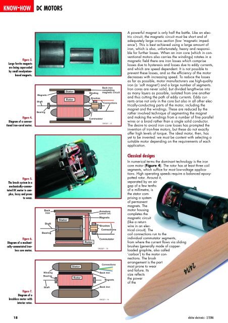
Large ferrite magnets<br />
are being superseded<br />
by small neodymiumbased<br />
magnets.<br />
Figure 4.<br />
Diagram <strong>of</strong> a conventional<br />
iron-cored motor.<br />
Figure 5.<br />
The brush system in a<br />
mechanically-commutated<br />
DC motor is complex,<br />
lossy and prone<br />
to wear.<br />
Figure 6.<br />
Diagram <strong>of</strong> a mechanically-commutatedironless<br />
core motor.<br />
Figure 7.<br />
Diagram <strong>of</strong> a<br />
brushless motor with<br />
interior rotor.<br />
18<br />
Magnets<br />
Shaft<br />
Bearing<br />
Back<br />
iron<br />
Shaft<br />
Bearing<br />
Stator<br />
Stator<br />
Rotor<br />
Winding<br />
Brushes<br />
Back iron<br />
completing<br />
magnetic circuit<br />
Connections<br />
Commutator<br />
050321 - 12<br />
Rotor<br />
Armature<br />
(potted coil)<br />
Magnets<br />
Brushes<br />
Connections<br />
Commutator<br />
050321 - 13<br />
Connections<br />
Winding Back iron<br />
Bearing<br />
Rotor<br />
Magnets<br />
Shaft<br />
Stator<br />
Back iron<br />
050321 - 14<br />
A powerful magnet is only half the battle. Like an electric<br />
circuit, the magnetic circuit must be short and <strong>of</strong><br />
adequately large cross section (low ‘magnetic impedance’).<br />
This is best achieved using a large amount <strong>of</strong><br />
iron, which is also, unfortunately, heavy and responsible<br />
for further losses. When an iron core (which in conventional<br />
motors also carries the windings) rotates in a<br />
magnetic field there are iron losses which comprise<br />
losses due to hysteresis and losses due to eddy currents,<br />
and which are speed dependent. It is not possible to<br />
prevent these losses, and so the efficiency <strong>of</strong> the motor<br />
decreases with increasing speed. To reduce the losses<br />
as far as possible, motor manufacturers use high-quality<br />
iron (a ‘s<strong>of</strong>t magnet’) and a large number <strong>of</strong> segments.<br />
Iron cores are never solid, but divided lengthwise into<br />
as many layers as possible, isolated from one another<br />
and thus cutting the path <strong>of</strong> eddy currents. Eddy currents<br />
arise not only in the core but also in all other electrically-conducting<br />
parts <strong>of</strong> the motor, including the<br />
magnet and the windings. These are reduced by the<br />
rather involved technique <strong>of</strong> segmenting the magnet<br />
and making the windings from a number <strong>of</strong> fine parallel<br />
wires or a braid rather than a single solid conductor.<br />
The desire to avoid iron core losses has prompted the<br />
invention <strong>of</strong> iron-free motors, but these do not exactly<br />
<strong>of</strong>fer high levels <strong>of</strong> torque. The ideal motor, then, has<br />
yet to be invented: we must be content with selecting a<br />
suitable motor depending on the requirements <strong>of</strong> each<br />
application.<br />
Classical designs<br />
In numerical terms the dominant technology is the iron<br />
core motor (Figure 4). The rotor has at least three coil<br />
segments, which suffice for most low-voltage applications.<br />
High operating speeds require a balanced epoxypotted<br />
rotor. Around it,<br />
separated by an air<br />
gap <strong>of</strong> a few tenths<br />
<strong>of</strong> a millimetre, is<br />
the stator comprising<br />
a system<br />
<strong>of</strong> permanent<br />
magnets. The<br />
motor housing<br />
completes the<br />
magnetic circuit<br />
(like a return<br />
wire in an electrical<br />
circuit). The<br />
coil connections run to the<br />
individual commutator segments,<br />
from where the current flows via sliding<br />
brushes (generally made <strong>of</strong> copperloaded<br />
graphite, also called<br />
‘carbon’) to the motor connections.<br />
The brush<br />
arrangement is the part<br />
most prone to wear<br />
and failure. Its<br />
size reflects<br />
the power<br />
<strong>of</strong> the<br />
elektor electronics - 2/<strong>2006</strong>


