

FEBRUARY 2006 £3.80 - Index of
FEBRUARY 2006 £3.80 - Index of
FEBRUARY 2006 £3.80 - Index of

You also want an ePaper? Increase the reach of your titles
YUMPU automatically turns print PDFs into web optimized ePapers that Google loves.
HANDS-ON RC MODELLING<br />
The environment<br />
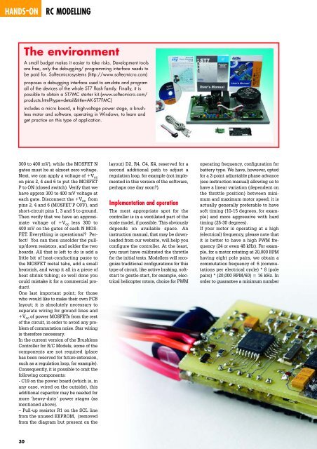
A small budget makes it easier to take risks. Development tools<br />
are free, only the debugging/ programming interface needs to<br />
be paid for. S<strong>of</strong>tecmicrosystems (http://www.s<strong>of</strong>tecmicro.com)<br />
proposes a debugging interface used to emulate and program<br />
all <strong>of</strong> the devices <strong>of</strong> the whole ST7 flash family. Finally, it is<br />
possible to obtain a ST7MC starter kit.(www.s<strong>of</strong>tecmicro.com/<br />
products.html?type=detail&title=AK-ST7FMC)<br />
includes a micro board, a high-voltage power stage, a brushless<br />
motor and s<strong>of</strong>tware, operating in Windows, to learn and<br />
get practice on this type <strong>of</strong> application.<br />
300 to 400 mV), while the MOSFET N<br />
gates must be at almost zero voltage.<br />
Next, we can apply a voltage <strong>of</strong> +V cc<br />
on pins 2, 4 and 6 to put the MOSFET<br />
P to ON (closed switch). Verify that we<br />
have approx 300 to 400 mV voltage at<br />
each gate. Disconnect the +V cc from<br />
pins 2, 4 and 6 (MOSFET P OFF), and<br />
short-circuit pins 1, 3 and 5 to ground.<br />
Then verify that we have an approximate<br />
voltage <strong>of</strong> +V cc less 300 to<br />
400 mV on the gates <strong>of</strong> each N MOS-<br />
FET. Everything is operational? Perfect!<br />
You can then unsolder the pullup/down<br />
resistors, and solder the two<br />
boards. All that is left to do is add a<br />
little bit <strong>of</strong> heat-conducting paste to<br />
the MOSFET metal tabs, add a small<br />
heatsink, and wrap it all in a piece <strong>of</strong><br />
heat shrink tubing; so well done you<br />
could mistake it for a commercial product!.<br />
One last important point; for those<br />
who would like to make their own PCB<br />
layout; it is absolutely necessary to<br />
separate wiring for ground lines and<br />
+V cc <strong>of</strong> power MOSFETs from the rest<br />
<strong>of</strong> the circuit, in order to avoid any problem<br />
<strong>of</strong> commutation noise. Star wiring<br />
is therefore necessary.<br />
In the current version <strong>of</strong> the Brushless<br />
Controller for R/C Models, some <strong>of</strong> the<br />
components are not required (place<br />
has been reserved for future extension,<br />
such as a regulation loop, for example).<br />
Consequently, it is possible to omit the<br />
following components:<br />
- C19 on the power board (which is, in<br />
any case, wired on the outside), this<br />
additional capacitor may be needed for<br />
more ‘heavy-duty’ power stages (as<br />
mentioned above).<br />
– Pull-up resistor R1 on the SCL line<br />
from the unused EEPROM, (removed<br />
from the diagram but present on the<br />
30<br />
layout) D2, R4, C4, K4, reserved for a<br />
second additional path to adjust a<br />
regulation loop, for example (not implemented<br />
in this version <strong>of</strong> the s<strong>of</strong>tware,<br />
perhaps one day soon?).<br />
Implementation and operation<br />
The most appropriate spot for the<br />
controller is in a ventilated part <strong>of</strong> the<br />
scale model, if possible. This obviously<br />
depends on available space. An<br />
instruction manual, that may be downloaded<br />
from our website, will help you<br />
configure the controller. At the least,<br />
you must have calibrated the throttle<br />
for the initial tests. Modellers will recognize<br />
traditional configurations for this<br />
type <strong>of</strong> circuit, like active braking, s<strong>of</strong>tstart<br />
to gentle start, for example, electrical<br />
helicopter rotors, choice for PWM<br />
operating frequency, configuration for<br />
battery type. We have, however, opted<br />
for a 2-point adjustable phase advance<br />
(see instruction manual) allowing us to<br />
have a linear variation (dependent on<br />
the throttle position) between minimum<br />
and maximum motor speed; it is<br />
actually generally preferable to have<br />
s<strong>of</strong>t timing (10-15 degrees, for example)<br />
and more aggressive with hard<br />
timing (25-30 degrees).<br />
If your motor is operating at a high<br />
(electrical) frequency, please note that<br />
it is better to have a high PWM frequency<br />
(24 or even 48 kHz). For example,<br />
for a motor rotating at 20,000 RPM<br />
having eight pole pairs, we obtain a<br />
commutation frequency <strong>of</strong>: 6 (commutations<br />
per electrical cycle) * 8 (pole<br />
pairs) * (20,000 RPM/60) = 16 kHz. In<br />
order to guarantee a minimum number


