

FEBRUARY 2006 £3.80 - Index of
FEBRUARY 2006 £3.80 - Index of
FEBRUARY 2006 £3.80 - Index of

Create successful ePaper yourself
Turn your PDF publications into a flip-book with our unique Google optimized e-Paper software.
nections that are essential for a ‘quick<br />
start’, so you can get your bearings as<br />
fast as possible. The connections not<br />
shown in the figure must always<br />
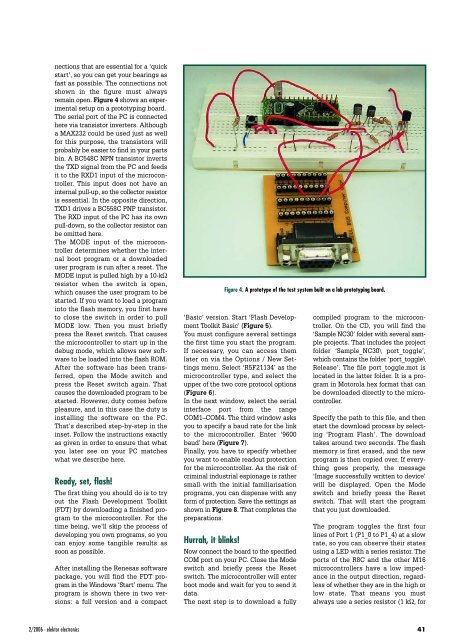
remain open. Figure 4 shows an experimental<br />
setup on a prototyping board.<br />
The serial port <strong>of</strong> the PC is connected<br />
here via transistor inverters. Although<br />
a MAX232 could be used just as well<br />
for this purpose, the transistors will<br />
probably be easier to find in your parts<br />
bin. A BC548C NPN transistor inverts<br />
the TXD signal from the PC and feeds<br />
it to the RXD1 input <strong>of</strong> the microcontroller.<br />
This input does not have an<br />
internal pull-up, so the collector resistor<br />
is essential. In the opposite direction,<br />
TXD1 drives a BC558C PNP transistor.<br />
The RXD input <strong>of</strong> the PC has its own<br />
pull-down, so the collector resistor can<br />
be omitted here.<br />
The MODE input <strong>of</strong> the microcontroller<br />
determines whether the internal<br />
boot program or a downloaded<br />
user program is run after a reset. The<br />
MODE input is pulled high by a 10-kΩ<br />
resistor when the switch is open,<br />
which causes the user program to be<br />
started. If you want to load a program<br />
into the flash memory, you first have<br />
to close the switch in order to pull<br />
MODE low. Then you must briefly<br />
press the Reset switch. That causes<br />
the microcontroller to start up in the<br />
debug mode, which allows new s<strong>of</strong>tware<br />
to be loaded into the flash ROM.<br />
After the s<strong>of</strong>tware has been transferred,<br />
open the Mode switch and<br />
press the Reset switch again. That<br />
causes the downloaded program to be<br />
started. However, duty comes before<br />
pleasure, and in this case the duty is<br />
installing the s<strong>of</strong>tware on the PC.<br />
That’s described step-by-step in the<br />
inset. Follow the instructions exactly<br />
as given in order to ensure that what<br />
you later see on your PC matches<br />
what we describe here.<br />
Ready, set, flash!<br />
The first thing you should do is to try<br />
out the Flash Development Toolkit<br />
(FDT) by downloading a finished program<br />
to the microcontroller. For the<br />
time being, we’ll skip the process <strong>of</strong><br />
developing you own programs, so you<br />
can enjoy some tangible results as<br />
soon as possible.<br />
After installing the Renesas s<strong>of</strong>tware<br />
package, you will find the FDT program<br />
in the Windows ‘Start’ menu. The<br />
program is shown there in two versions:<br />
a full version and a compact<br />
Figure 4. A prototype <strong>of</strong> the test system built on a lab prototyping board.<br />
‘Basic’ version. Start ‘Flash Development<br />
Toolkit Basic’ (Figure 5).<br />
You must configure several settings<br />
the first time you start the program.<br />
If necessary, you can access them<br />
later on via the Options / New Settings<br />
menu. Select ‘R5F21134’ as the<br />
microcontroller type, and select the<br />
upper <strong>of</strong> the two core protocol options<br />
(Figure 6).<br />
In the next window, select the serial<br />
interface port from the range<br />
COM1–COM4. The third window asks<br />
you to specify a baud rate for the link<br />
to the microcontroller. Enter ‘9600<br />
baud’ here (Figure 7).<br />
Finally, you have to specify whether<br />
you want to enable readout protection<br />
for the microcontroller. As the risk <strong>of</strong><br />
criminal industrial espionage is rather<br />
small with the initial familiarisation<br />
programs, you can dispense with any<br />
form <strong>of</strong> protection. Save the settings as<br />
shown in Figure 8. That completes the<br />
preparations.<br />
Hurrah, it blinks!<br />
Now connect the board to the specified<br />
COM port on your PC. Close the Mode<br />
switch and briefly press the Reset<br />
switch. The microcontroller will enter<br />
boot mode and wait for you to send it<br />
data.<br />
The next step is to download a fully<br />
compiled program to the microcontroller.<br />
On the CD, you will find the<br />
‘Sample NC30’ folder with several sample<br />
projects. That includes the project<br />
folder ‘Sample_NC30\ port_toggle’,<br />
which contains the folder ‘port_toggle\<br />
Release’. The file port_toggle.mot is<br />
located in the latter folder. It is a program<br />
in Motorola hex format that can<br />
be downloaded directly to the microcontroller.<br />
Specify the path to this file, and then<br />
start the download process by selecting<br />
‘Program Flash’. The download<br />
takes around two seconds. The flash<br />
memory is first erased, and the new<br />
program is then copied over. If everything<br />
goes properly, the message<br />
‘Image successfully written to device’<br />
will be displayed. Open the Mode<br />
switch and briefly press the Reset<br />
switch. That will start the program<br />
that you just downloaded.<br />
The program toggles the first four<br />
lines <strong>of</strong> Port 1 (P1_0 to P1_4) at a slow<br />
rate, so you can observe their states<br />
using a LED with a series resistor. The<br />
ports <strong>of</strong> the R8C and the other M16<br />
microcontrollers have a low impedance<br />
in the output direction, regardless<br />
<strong>of</strong> whether they are in the high or<br />
low state. That means you must<br />
always use a series resistor (1 kΩ, for<br />
2/<strong>2006</strong> - elektor electronics 41


