

FEBRUARY 2006 £3.80 - Index of
FEBRUARY 2006 £3.80 - Index of
FEBRUARY 2006 £3.80 - Index of

You also want an ePaper? Increase the reach of your titles
YUMPU automatically turns print PDFs into web optimized ePapers that Google loves.
HANDS-ON RC MODELLING<br />
conduct at the same time, which can<br />
cause a short-circuit and, in general,<br />
destroy the transistors), it is imperative<br />
to prioritize a very fast OFF setting and<br />
a slow ON setting. In this way, the<br />
BAT54C diodes allow for a very fast<br />
pull-up/down to the power MOSFET<br />
gates (to 0 or +Vbattery according to<br />
the type N or P <strong>of</strong> the MOSFET), while<br />
the ON setting is at 240 Ω (R37, for<br />
28<br />
PWM ON<br />
+VCC<br />
Figure 10. The double-sided board<br />
<strong>of</strong> the power stage.<br />
PWM OFF<br />
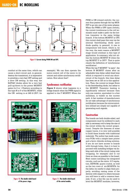
Figure 9. Current during PWM ON and OFF.<br />
+VCC<br />
050157 - 19<br />
example). We can then operate the<br />
motor-control cell <strong>of</strong> the micro to its<br />
utmost and utilise synchronous rectification.<br />
How about that?<br />
Synchronous rectification<br />
Figure 9 shows what happens in a<br />
bridge branch when the PWM signal is<br />
applied to the P MOSFET. When the<br />
Figure 11. The double-sided board<br />
<strong>of</strong> the control module.<br />
PWM is ON (closed switch), the current<br />
thus passes through the top MOS-<br />
FET to go into one <strong>of</strong> the motor phases.<br />
When the PWM is OFF (open switch),<br />
the current (continuous to the coil terminals)<br />
must make a path via the bottom<br />
transistor in the same bridge<br />
branch. If the bottom MOSFET is OFF,<br />
this current shall pass this way via the<br />
internal freewheeling diode (poor<br />
diode quality, in general). A rise in<br />
temperature will result, which is, by<br />
the way, the main reason a MOSFET<br />
stage would overheat in this type <strong>of</strong><br />
application. In summary, why not utilise<br />
the bottom MOSFET N when the<br />
top MOSFET P is OFF? That is quite<br />
clearly the definition <strong>of</strong> ‘synchronous<br />
rectification’.<br />
When the top P MOSFET “is open”, the<br />
bottom N MOSFET closes after an<br />
adjustable time delay called dead time<br />
which is required to avoid any shortcircuit<br />
<strong>of</strong> the branch; this time delay<br />
has been set at 325 ns in this application.<br />
Then, the current no longer flows<br />
to the freewheeling diode, but rather to<br />
the MOSFET. Transistor heating is<br />
significantly reduced because then<br />
only one resistor, equivalent to a few<br />
milliohms, is visible on the current<br />
path. A fair number <strong>of</strong> manufacturers<br />
do not take advantage <strong>of</strong> synchronous<br />
rectification because the microcontrollers<br />
utilised are simply not capable <strong>of</strong><br />
generating such signals.<br />
Construction<br />
The boards are both double-sided, and<br />
components must be soldered to each<br />
side (a necessary evil to keep the size <strong>of</strong><br />
the circuit within the correct proportions).<br />
Despite the fineness <strong>of</strong> some<br />
copper traces, it is very well possible<br />
to build these boards with traditional<br />
materials. The author has made numerous<br />
PCBs with a simple laser printer<br />
and a ferric chloride etching solution.<br />
If you do not have access to boards<br />
with through holes, then it is best to<br />
proceed with installing bridges via linking<br />
each side <strong>of</strong> the circuit (using wire<br />
wrapping, for example) and to cut<br />
them as close as possible to the board.<br />
Next comes installing the integrated<br />
circuits, such as the micro, 5-V regulators,<br />
EEPROM, quartz crystal, as well<br />
as the two rows <strong>of</strong> six MOSFETs: for<br />
the latter, be careful to align them properly,<br />
avoiding raising some <strong>of</strong> the<br />
devices with respect to others because<br />
you will have to add a common heatsink.<br />
If not, a fine file can be used to<br />
level the MOSFET modules; however,<br />
elektor electronics - 2/<strong>2006</strong>


