

FEBRUARY 2006 £3.80 - Index of
FEBRUARY 2006 £3.80 - Index of
FEBRUARY 2006 £3.80 - Index of

You also want an ePaper? Increase the reach of your titles
YUMPU automatically turns print PDFs into web optimized ePapers that Google loves.
KNOW-HOW DC MOTORS<br />
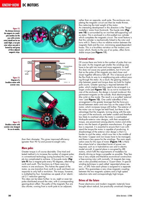
Figure 12.<br />
The distance between<br />
the magnets in a multipole<br />
machine (in this<br />
case with exterior<br />
rotor) should not be too<br />
small. Right, a ten-pole<br />
rotor where one pole is<br />
formed by each group<br />
<strong>of</strong> three adjacent<br />
magnetic strips.<br />
Figure 13.<br />
Diagram <strong>of</strong> a<br />
brushless motor with<br />
exterior rotor.<br />
Figure 14.<br />
Brushless motor with<br />
exterior rotor designed<br />
for use in models.<br />
20<br />
Shaft<br />
Rotor<br />
than their diameter. This gives improved efficiency<br />
(greater than 90 %) and power-to-weight ratio.<br />
More poles<br />
Stator<br />
Magnets<br />
Connections<br />
Bearing<br />
Back iron<br />
Winding<br />
050321 - 18<br />
Greater torque is <strong>of</strong> course desirable. One tried and<br />
tested method is to increase the number <strong>of</strong> magnet poles:<br />
in conventional technology (using brushes) this was simply<br />
too complicated to achieve. A four-pole motor (Figure<br />
9) has a magnet pole every 90 degrees, alternating<br />
north and south. This functions as if there were two<br />
motors in one enclosure. This halves the speed <strong>of</strong> the<br />
motor, as one transition from north to south and back corresponds<br />
to only half a revolution. The torque, however,<br />
is multiplied by four. Sometimes we speak <strong>of</strong> an ‘electrical<br />
2:1 reduction gearing’.<br />
This idea can be taken further: to six, eight or even ten<br />
poles distributed around the rotor, with a corresponding<br />
gearing-down effect. The paths <strong>of</strong> the magnetic flux are<br />
also shorter, running from a north pole to an adjacent,<br />
rather than an opposite, south pole. The enclosure completing<br />
the magnetic circuit can then be made thinner,<br />
thus reducing the total weight <strong>of</strong> the motor.<br />
An interesting development in this direction is the ‘Tango’<br />
modellers’ motor from Kontronik. The 6-pole rotor (Figure<br />
10) is surrounded by an iron-free self-supporting coil<br />
as stator. This is enclosed in a thin-walled iron cylinder<br />
which completes the magnetic circuit. The novel feature is<br />
that this cylinder is mechanically linked to the rotor and<br />
turns with it. There is thus no relative motion between the<br />
magnetic field and the iron, minimising speed-dependent<br />
losses. This is a brushless variation on the ironless core<br />
motor which, thanks to the use <strong>of</strong> six poles, <strong>of</strong>fers formidable<br />
torque (see Figure 11).<br />
External rotors<br />
Of course there are limits to the number <strong>of</strong> poles that can<br />
be used. As the magnets get smaller the windings also<br />
have to be split into more and more segments. In itself<br />
this does not cause any great problems, but it turns out<br />
that as the poles <strong>of</strong> the magnets are sited closer and<br />
closer together efficiency falls <strong>of</strong>f. This is because part <strong>of</strong><br />
the flux finds its way to a neighbouring pole without passing<br />
through the stator. As a result, the gearing relationship<br />
between speed and torque does not hold for higher<br />
pole counts. Greater spacing is required between the<br />
poles, which implies that they need to be arranged in a<br />
larger circle (see Figure 12). So as not to increase the<br />
size <strong>of</strong> the enclosure, the design is turned inside-out: thin<br />
permanent magnets on the outside, thick electromagnets<br />
(the coils) on the inside. The result is a so-called ‘external<br />
rotor’ (see Figure 13). One useful side-effect <strong>of</strong> this<br />
arrangement is the greater leverage that the force produced<br />
between stator and rotor has on the output <strong>of</strong> the<br />
motor, which increases torque still further. The exterior <strong>of</strong><br />
the motor can no longer be held fixed, but there is the<br />
advantage that the magnets, turning along with the exterior<br />
part <strong>of</strong> the enclosure, are better cooled and therefore<br />
less likely to overheat when the motor is overloaded.<br />
Multi-pole exterior rotor designs, with their exceptional<br />
torque, are pre-eminent among electric motors and strike<br />
terror into the hearts <strong>of</strong> gearbox manufacturers. If a gearbox<br />
is required, it is essential to ensure that it can withstand<br />
the torque the motor is capable <strong>of</strong> producing. A<br />
disadvantage <strong>of</strong> the exterior rotor design is that it is<br />
harder to cool the stator, which now lies in the middle <strong>of</strong><br />
the motor. Copper and iron losses have to be managed,<br />
and there is less space for the windings. The main application<br />
area for this type <strong>of</strong> motor (Figure 14) is therefore<br />
where brief or intermittent bursts <strong>of</strong> power are<br />
required, such as in hybrid-drive cars and in electric<br />
model aircraft. A special place is occupied by LRK<br />
motors, which fulfil the requirements <strong>of</strong> modellers for<br />
directly driving as large a propeller as possible. They feature<br />
a very simple and therefore economical construction:<br />
a free-running rotor with normally 14 magnets (ten magnets<br />
is also possible) encloses a 12-part stator. A special<br />
winding technique is used called ‘separated phase sectors’,<br />
or SPS: here each phase is assigned to a separate<br />
sector. This guarantees a very close magnetic coupling<br />
between the two magnetic systems and a high speed<br />
reduction ratio and correspondingly high torque.<br />
Drives <strong>of</strong> the future<br />
Power electronics and modern magnetic materials have<br />
brought about radical, but practically unnoticed changes<br />
elektor electronics - 2/<strong>2006</strong>


