Build your kids the sidewalk classic - Vintage Projects
Build your kids the sidewalk classic - Vintage Projects
Build your kids the sidewalk classic - Vintage Projects

You also want an ePaper? Increase the reach of your titles
YUMPU automatically turns print PDFs into web optimized ePapers that Google loves.
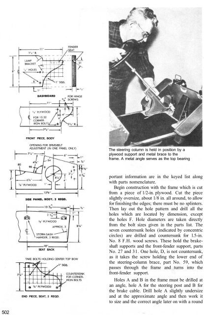
502<br />
FRONT PIECE, BODY<br />
OPENING FOR DRIVE-BELT<br />
ADJUSTMENT (IN ONE PANEL ONLY)<br />
SEAT BACK<br />
TAKE BOLTS HOLDING CENTER TOP BOW<br />
END PIECE, SEAT, 2 REQD.<br />
COUNTERSINK<br />
FOR CORNER-<br />
IRON BOLTS<br />
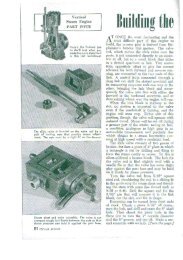
The steering column is held in position by a<br />
plywood support and metal brace to <strong>the</strong><br />
frame. A metal angle serves as <strong>the</strong> top bearing<br />
portant information are in <strong>the</strong> keyed list along<br />
with parts nomenclature.<br />
Begin construction with <strong>the</strong> frame which is cut<br />
from a piece of 1/2-in. plywood. Cut <strong>the</strong> piece<br />
slightly oversize, about 1/8 in. all around, to allow<br />
for finishing <strong>the</strong> edges; <strong>the</strong>re must be no splinters.<br />
Then lay out <strong>the</strong> hole pattern and drill all <strong>the</strong><br />
holes which are located by dimension, except<br />
<strong>the</strong> holes F. Hole diameters are taken directly<br />
from <strong>the</strong> bolt sizes given in <strong>the</strong> parts list. The<br />
seven countersunk holes (indicated by concentric<br />
circles) are drilled and countersunk for l.5-in.<br />
No. 8 F.H. wood screws. These hold <strong>the</strong> brakeshaft<br />
supports and <strong>the</strong> front-fender support, parts<br />
No. 27 and 31. One hole, D, is not countersunk,<br />
as it takes <strong>the</strong> screw holding <strong>the</strong> lower end of<br />
<strong>the</strong> steering-column brace, part No. 59, which<br />
passes through <strong>the</strong> frame and turns into <strong>the</strong><br />
front-fender support.<br />
Holes A and B in <strong>the</strong> frame must be drilled at<br />
an angle, hole A for <strong>the</strong> steering post and B for<br />
<strong>the</strong> brake cable. Drill hole A slightly undersize<br />
and at <strong>the</strong> approximate angle and <strong>the</strong>n work it<br />
to size and <strong>the</strong> correct angle later on with a round