Build your kids the sidewalk classic - Vintage Projects
Build your kids the sidewalk classic - Vintage Projects
Build your kids the sidewalk classic - Vintage Projects

Create successful ePaper yourself
Turn your PDF publications into a flip-book with our unique Google optimized e-Paper software.
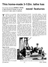
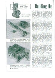
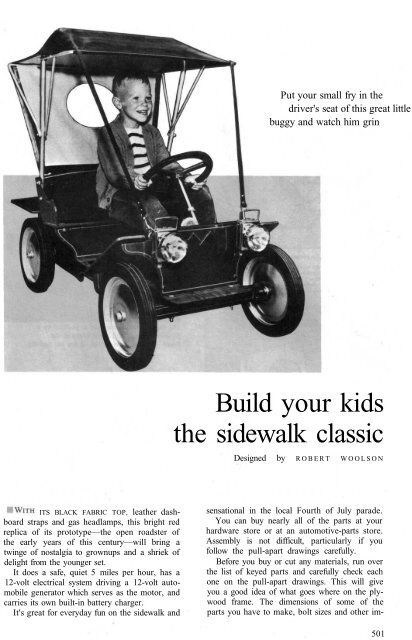
ITS BLACK FABRIC TOP, lea<strong>the</strong>r dashboard<br />
straps and gas headlamps, this bright red<br />
replica of its prototype—<strong>the</strong> open roadster of<br />
<strong>the</strong> early years of this century—will bring a<br />
twinge of nostalgia to grownups and a shriek of<br />
delight from <strong>the</strong> younger set.<br />
It does a safe, quiet 5 miles per hour, has a<br />
12-volt electrical system driving a 12-volt automobile<br />
generator which serves as <strong>the</strong> motor, and<br />
carries its own built-in battery charger.<br />
It's great for everyday fun on <strong>the</strong> <strong>sidewalk</strong> and<br />
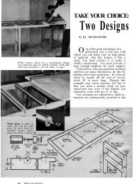
Put <strong>your</strong> small fry in <strong>the</strong><br />
driver's seat of this great little<br />
buggy and watch him grin<br />
<strong>Build</strong> <strong>your</strong> <strong>kids</strong><br />
<strong>the</strong> <strong>sidewalk</strong> <strong>classic</strong><br />
Designed by ROBERT WOOLSON<br />
sensational in <strong>the</strong> local Fourth of July parade.<br />
You can buy nearly all of <strong>the</strong> parts at <strong>your</strong><br />
hardware store or at an automotive-parts store.<br />
Assembly is not difficult, particularly if you<br />
follow <strong>the</strong> pull-apart drawings carefully.<br />
Before you buy or cut any materials, run over<br />
<strong>the</strong> list of keyed parts and carefully check each<br />
one on <strong>the</strong> pull-apart drawings. This will give<br />
you a good idea of what goes where on <strong>the</strong> plywood<br />
frame. The dimensions of some of <strong>the</strong><br />
parts you have to make, bolt sizes and o<strong>the</strong>r im-<br />
501
502<br />
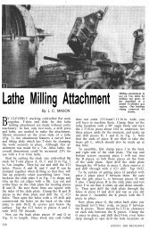
FRONT PIECE, BODY<br />
OPENING FOR DRIVE-BELT<br />
ADJUSTMENT (IN ONE PANEL ONLY)<br />
SEAT BACK<br />
TAKE BOLTS HOLDING CENTER TOP BOW<br />
END PIECE, SEAT, 2 REQD.<br />
COUNTERSINK<br />
FOR CORNER-<br />
IRON BOLTS<br />
The steering column is held in position by a<br />
plywood support and metal brace to <strong>the</strong><br />
frame. A metal angle serves as <strong>the</strong> top bearing<br />
portant information are in <strong>the</strong> keyed list along<br />
with parts nomenclature.<br />
Begin construction with <strong>the</strong> frame which is cut<br />
from a piece of 1/2-in. plywood. Cut <strong>the</strong> piece<br />
slightly oversize, about 1/8 in. all around, to allow<br />
for finishing <strong>the</strong> edges; <strong>the</strong>re must be no splinters.<br />
Then lay out <strong>the</strong> hole pattern and drill all <strong>the</strong><br />
holes which are located by dimension, except<br />
<strong>the</strong> holes F. Hole diameters are taken directly<br />
from <strong>the</strong> bolt sizes given in <strong>the</strong> parts list. The<br />
seven countersunk holes (indicated by concentric<br />
circles) are drilled and countersunk for l.5-in.<br />
No. 8 F.H. wood screws. These hold <strong>the</strong> brakeshaft<br />
supports and <strong>the</strong> front-fender support, parts<br />
No. 27 and 31. One hole, D, is not countersunk,<br />
as it takes <strong>the</strong> screw holding <strong>the</strong> lower end of<br />
<strong>the</strong> steering-column brace, part No. 59, which<br />
passes through <strong>the</strong> frame and turns into <strong>the</strong><br />
front-fender support.<br />
Holes A and B in <strong>the</strong> frame must be drilled at<br />
an angle, hole A for <strong>the</strong> steering post and B for<br />
<strong>the</strong> brake cable. Drill hole A slightly undersize<br />
and at <strong>the</strong> approximate angle and <strong>the</strong>n work it<br />
to size and <strong>the</strong> correct angle later on with a round
BRAKE-BAND<br />
TIGHTENER<br />
BRAKE ASSEMBLY<br />
I DOTTED LINES<br />
I INDICATE POSI-<br />
' TION OF RUBBER<br />
FLOOR MAT<br />
CHASSIS FRAME, 1/2" PLYWOOD<br />
SHAFT<br />
COLLARS<br />
file when you fit <strong>the</strong> steering post. Also you'll<br />
have to do some work with <strong>the</strong> round file to bring<br />
hole B to <strong>the</strong> correct angle to take <strong>the</strong> brake<br />
cable without binding. Holes C, E, G and H are<br />
for <strong>the</strong> passage of wiring through <strong>the</strong> frame and<br />
only <strong>the</strong> approximate location is indicated. The<br />
four holes F take 10-24 F.H. screws (with nuts)<br />
and hold two 3-in. corner irons which serve<br />
as motor-mounting brackets. It's a good idea to<br />
have <strong>your</strong> motor on hand so that you can determine<br />
<strong>the</strong> distance between <strong>the</strong> pairs of holes,<br />
as it may vary from that given. Be sure of <strong>the</strong><br />
over-all dimensions of <strong>the</strong> battery case before<br />
you cut <strong>the</strong> well and make <strong>the</strong> support.<br />
The front axle consists of a length of hardwood<br />
and two steel straps. Note in <strong>the</strong> pull-apart<br />
GROUND-WHEEL DRIVE<br />
BRAKE ECCENTRIC ASSEMBLY<br />
503
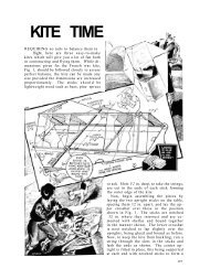
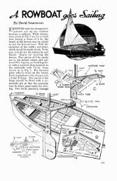
KEYED PULL-APART VIEW<br />
(REAR WHEELS, FABRIC TOP,<br />
WIRING AND BATTERY NOT SHOWN)
KEYED LEGENDS<br />
1. WHEEL, SEMI-PNEUMATIC, 12 x 1.75. BALL-BEAR-<br />
ING. FOUR REQUIRED (SPARE WHEEL OPTIONAL)<br />
2. SHAFT COLLAR, 1/2 IN.<br />
3. WHEEL SPINDLE, 1/2 x APPROX. 3 IN. STEEL. TH'D.<br />
1/2-13. TWO REQUIRED<br />
4. HEX NUT, 1/2 IN., WITH WASHER<br />
5. HEX NUT, 1/2 IN., TWO REQUIRED<br />
6. HEX NUTS AND LOCK WASHERS, 1/4 IN.<br />
7. FLAT SPACER WASHERS, ONLY TWO SHOWN; FOUR<br />
REQUIRED<br />
8. AXLE STRAPS, TWO REQUIRED<br />
9. AXLE, HARDWOOD<br />
10. SAME AS PART NO. 6<br />
11. SAME AS PART NO. 5<br />
12. HEX-HEAD MACHINE BOLT, 1/4 X 2 1/3"<br />
13. HEX NUT AND WASHER, VA IN., TURNS ONTO END<br />
OF STEERING ROD<br />
14. TIE ROD<br />
15. STEERING ROD<br />
16. SAME AS PART NO. 12. NOTE THAT BOLTS NO. 12<br />
AND 16 PASS THROUGH AXLE ONLY, NOT<br />
THROUGH FRAME<br />
17. KINGBOLT, 1/2 x 2 1/2 IN., TWO REQUIRED<br />
18. PIPE TEE, 1/4-IN. TWO REQUIRED. THREADS<br />
REAMED OUT TO TAKE 1/2-IN. KINGBOLT<br />
19. STEERING ARM, TWO REQUIRED, R. AND L., ONE<br />
HAS THIRD HOLE FOR STEERING ROD<br />
20. LOCK WASHER, 1/2 IN.<br />
21. HEX NUT, 1/2 IN.<br />
22. CHASSIS FRAME, 1/2-IN. PLYWOOD<br />
23. CARRIAGE BOLT, 1/4 X 3 IN. TWO REQUIRED<br />
24. FOOT SWITCH, DPST, PUSH-BUTTON TYPE, NOR-<br />
MALLY OFF<br />
25. ROUND-HEAD 10-24 SCREW, 3/4 IN. LONG. RE-<br />
QUIRES TWO NUTS, LOCK WASHER BETWEEN<br />
NUTS AND TWO SPACER WASHERS<br />
26. BRAKE PEDAL<br />
27. FRONT-FENDER SUPPORT<br />
28. SPOTLIGHT SWITCH, LEVER-ACTUATED, SPDT,<br />
BUT USED AS SPST ONLY<br />
29. SHAFT COLLAR, 1/2-IN., ACTUATES SPOTLIGHT<br />
SWITCH. A SECOND COLLAR IS REQUIRED ON<br />
BRAKE SHAFT TO HOLD IT IN POSITION AFTER<br />
ASSEMBLY<br />
30. WIRE BRAKE CABLE 1/8-IN. DIAMETER, OVERALL<br />
LENGTH APPROX. 28 1/2"<br />
31. BRAKE-SHAFT SUPPORT, OR BEARING. TWO RE-<br />
QUIRED<br />
32. BRAKE SHAFT, 1/2 x 17-IN. STEEL SHAFTING<br />
33. BRAKE ECCENTRIC, 3-IN.-DIA. V-PULLEY<br />
34. BRAKE RETURN SPRING, 6 3/4 IN. LONG, 1-IN.-DIA.<br />
COILS<br />
35. ROUND-HEAD 10-24 SCREW. 2 IN. LONG. LOCKS<br />
END OF BRAKE BAND<br />
36. BRAKE-BAND TIGHTENER, 2-IN. V-PULLEY<br />
37. BRAKE BAND, 1/2-IN. V-BELT, OVERALL LENGTH<br />
APPROX. 16 1/2"<br />
38. BRAKE-BAND LUG, 1/8 x 1 x 6-IN. STEEL OUTER<br />
END GIVEN ONE-QUARTER TWIST<br />
39. SHAFT COLLAR, 1/2-IN.<br />
40. BRAKE STUD, 5/16-.|N. STEEL, TWO REQUIRED.<br />
THREAD 5/16-18 AND FIT EACH WITH TWO HEX NUTS<br />
41. REAR AXLE, 1/2 x 23 1/4-IN. LENGTH OF DRILL ROD<br />
42. BRAKE DRUM, 4-IN. V-PULLEY. DRILL 5/16-IN. HOLES<br />
THROUGH WEB ON 2 1/8-IN. CENTERS FOR BRAKE<br />
STUDS<br />
43. BALL-BEARING PILLOW BLOCK FOR 1/2-IN. SHAFT.<br />
TWO REQUIRED<br />
44. MACHINE BOLT, 1/4 X 1 IN. WITH NUT AND LOCK<br />
WASHER. TWO REQUIRED. THESE BOLTS JOIN<br />
MOTOR MOUNTING LUGS TO 3-IN. CORNER IRONS,<br />
ONE LEG OF EACH IRON BEING CUT TO 2 1/8 IN.<br />
LENGTH. DRILL HOLES FOR BOLTS CENTERING 15/8<br />
IN. ABOVE THE CORNER-IRON BEND<br />
45. DPDT TOGGLE SWITCH. SEE WIRING DIAGRAM<br />
46. BATTERY WELL AND SUPPORT<br />
47. CORNER IRON, TWO REQUIRED TO SUPPORT<br />
DASHBOARD **<br />
48. HEAD LAMP BRACKET<br />
49. HEAD LAMP, DRY-CELL POWERED, TWO REQUIRED<br />
50. PEDAL. ACTUATES START-STOP SWITCH<br />
51. FRONT FENDER, TWO REQUIRED. EACH CUT FROM<br />
3/8-IN. PLYWOOD, 4 IN. WIDE, 12 IN. LONG WITH<br />
UPPER CORNERS ROUNDED TO 1-IN. RADIUS,<br />
LOWER OUTSIDE CORNER TO 2-IN. RADIUS<br />
52. DASHBOARD, 3/4-|N. PLYWOOD<br />
53. SOFT-IRON RIVETS, 1/8 x 3/4 IN. EXACT LENGTH<br />
DEPENDS ON WIDTH OF SHAFT COLLAR USED<br />
54. STEERING CRANK<br />
55. SHAFT COLLAR, 1/2 IN. NOTE THAT PARTS NO. 54<br />
AND 55 ARE JOINED WITH RIVETS, PART NO. 53<br />
56. NO. 8 WOOD SCREW 1 1/2- IN. LONG<br />
57. STEERING COLUMN, 1/2 IN. DIA., 18 IN. LONG,<br />
STEEL SHAFTING<br />
58. STEERING-COLUMN SUPPORT, 3/4-|N. PLYWOOD<br />
59. STEERING-COLUMN BRACE<br />
60. SCREWEYE, 1/2 IN. TWO REQUIRED. TAKES SWIVEL<br />
SNAP ON TOP STRAP<br />
61. FRONT PIECE, BODY<br />
62. SHEET-METAL SCREW, SIZE 1/2—8 (OR 10), BINDER<br />
HEAD, FIVE REQUIRED<br />
63. CORNER IRON, 1 IN., FIVE REQUIRED TO ATTACH<br />
BODY TO FRAME. EIGHT REQUIRED FOR JOINING<br />
THE FOUR PARTS OF BODY<br />
64. DRIVING AND DRIVEN V-PULLEYS, DRIVING PULLEY,<br />
2 IN. DIA., 5/8-IN. BORE. DRIVEN PULLEY, 10 IN.<br />
DIA., 1/2-BORE. USE 1/2-IN, V-BELT, 34 IN. LONG<br />
65. TURNBUCKLE, SIZE (CLOSED) 5 1/4 N HOLDS MO-<br />
TOR IN FIXED POSITION<br />
66. AUTO GENERATOR, 12-VOLT. SERVES AS MOTOR<br />
WITHOUT ANY ALTERATION<br />
67. CARRIAGE BOLTS, VA X V/Z IN. FOUR REQUIRED<br />
WITH HEX NUTS AND WASHERS<br />
68. CHARGER, 12-VOLT<br />
69. TURNBUCKLE, PART NO. 65, IS FITTED WITH NUTS<br />
AND LOCK WASHERS TO PREVENT IT FROM LOOS-<br />
ENING<br />
70. BACK PIECE, BODY, 3/8x 6 5/16 x 15 3/16-IN. PLYWOOD<br />
71. SIDE PIECE, BODY. TWO REQUIRED. ONLY OWE<br />
HAS OPENING FOR BELT ADJUSTMENT<br />
72. BUTT HINGE, 1 1/2-IN., TWO REQUIRED<br />
73. BEARING, TOP END OF STEERING COLUMN<br />
74. SCREW, 10-24, 1 IN. LONG<br />
75. CORNER IRONS, 1-IN. AND 3-IN. SIZES, TWO RE-<br />
QUIRED OF EACH<br />
76. REAR FENDER, 3/8 x 4 x 12-IN. PLYWOOD WITH<br />
THREE CORNERS ROUNDED TO 1-IN. RADIUS<br />
77. RUBBER HOSE, 5/8-IN. O.D.<br />
78. STEERING WHEEL, 1/2-IN. BORE, 10 1/4-IN., DIA.,<br />
CAST-IRON V-PULLEY<br />
79. SHAFT COLLAR, 1/2-IN.<br />
80. ELECTRICIAN'S BLACK PLASTIC TAPE<br />
81. SIDE OF SEAT, TWO REQUIRED<br />
82. SEAT BOTTOM, 3/8.|N. PLYWOOD. MEASURES 8 1/4-<br />
IN. WIDE, 21 7/8-IN. ON LONG SIDE, 20 IN. ON SHORT<br />
SIDE. PADDED WITH CORRUGATED-RUBBER STAIR<br />
TREAD<br />
83. SEAT BACK<br />
84. MOTOR-COMPARTMENT COVER, OR DECK. 3/8 x<br />
8 3/4 x 16-IN. PLYWOOD<br />
85. DECK HANDLE<br />
86. LEATHER STRAP, TWO REQUIRED WITH BUCKLES<br />
87. STOPLIGHT, 12-VOLT<br />
88. HOOK AND EYE, 31/2 IN., HOLDS HINGED SEAT IN<br />
DOWN POSITION. EYE SCREWS INTO BACK OF<br />
SEAT NEAR BOTTOM. HOOK SCREWS INTO FRAME<br />
* PURCHASE A 24-IN. LENGTH OF DRILL ROD AND CUT<br />
TO REQUIRED LENGTH AFTER MAKING TRIAL AS-<br />
SEMBLY. LENGTH MAY VARY FROM THAT GIVEN<br />
DUE TO POSSIBLE VARIATIONS IN WIDTH THROUGH<br />
PILLOW-BLOCK BEARINGS AND WHEEL HUBS<br />
** INSIDE CORNER IRONS ARE USED THROUGHOUT<br />
ASSEMBLY. ALL 1-IN. IRONS JOINING BODY PARTS<br />
ARE HELD WITH 10-24 SCREWS AND SQUARE NUTS<br />
505
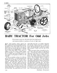
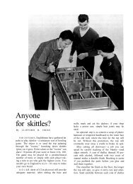
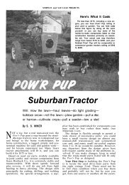
Battery-powered headlights snap onto metal brackets<br />
attached to <strong>the</strong> dashboard. The brackets come<br />
with <strong>the</strong> lamps. Note also <strong>the</strong> construction of <strong>the</strong><br />
front axle and <strong>the</strong> steering-knuckle assembly<br />
506
The brake band is a 1/2-in. V-belt anchored to a stationary lug and a tightener, and<br />
passes around a V-pulley on <strong>the</strong> axle. Note <strong>the</strong> two studs which engage <strong>the</strong> wheel<br />
view that <strong>the</strong>re are three pairs of bolts that pass<br />
through <strong>the</strong> axle, <strong>the</strong> two kingbolts, <strong>the</strong> pair of<br />
carriage bolts holding <strong>the</strong> frame to <strong>the</strong> axle,<br />
and a pair of machine bolts that hold <strong>the</strong> three<br />
parts of <strong>the</strong> axle toge<strong>the</strong>r. The wheel spindles<br />
swing on <strong>the</strong> kingbolts, which pivot 1/4-in. pipe<br />
tees. Threads in <strong>the</strong> body of <strong>the</strong> latter are reamed<br />
out to take <strong>the</strong> kingbolts in a close fit. A hex nut,<br />
lock washer and a steering arm are placed on<br />
each spindle before turning <strong>the</strong> latter into <strong>the</strong><br />
threaded stem of each tee. You'll see <strong>the</strong> order<br />
of assembly in <strong>the</strong> pull-apart view. A shaft collar<br />
with setscrews holds each wheel.<br />
Assemble <strong>the</strong> rear axle in its bearings on <strong>the</strong><br />
frame. Then make <strong>the</strong> brake-shaft supports and<br />
screw <strong>the</strong>m in place on <strong>the</strong> underside of <strong>the</strong><br />
frame, noting that <strong>the</strong> one that is grooved for<br />
<strong>the</strong> brake-band lug goes on <strong>the</strong> right side of <strong>the</strong><br />
frame, viewed from <strong>the</strong> front. The complete<br />
brake assembly is shown pulled apart. There<br />
are two points to note especially in this assembly.<br />
First, <strong>the</strong> brake-band lug, part No. 38, drops<br />
into <strong>the</strong> groove in <strong>the</strong> brake-shaft support. The<br />
wood screw holding it in <strong>the</strong> groove passes<br />
through <strong>the</strong> frame from <strong>the</strong> top. side, through<br />
<strong>the</strong> lug and is turned into <strong>the</strong> brake-shaft support.<br />
The inner end of <strong>the</strong> lug is held by a 10-24<br />
screw (with nut) which passes through a hole in<br />
<strong>the</strong> frame. This hole must be drilled through <strong>the</strong><br />
frame after <strong>the</strong> parts are located. Second, <strong>the</strong><br />
screw holding <strong>the</strong> forward end of <strong>the</strong> brake<br />
band in <strong>the</strong> groove in <strong>the</strong> brake-band tightener,<br />
part No. 36, passes through <strong>the</strong> band and a hole<br />
in <strong>the</strong> tightener and shaft.<br />
Parts of <strong>the</strong> brake-eccentric assembly are<br />
shown on page 503. A 5/16 x 1 3/8-in. stud is crossdrilled<br />
near <strong>the</strong> unthreaded end to take <strong>the</strong> end<br />
of <strong>the</strong> brake cable. A nut and washer are run<br />
down on <strong>the</strong> stud and <strong>the</strong> cross-drilled end inserted<br />
in a hole drilled through one side of <strong>the</strong><br />
pulley (eccentric) rim. The free end of <strong>the</strong><br />
cable is passed through <strong>the</strong> hole near <strong>the</strong> end<br />
of <strong>the</strong> stud and <strong>the</strong> nut tightened, clamping<br />
<strong>the</strong> end of <strong>the</strong> cable securely in place. This arrangement<br />
provides adjustment of <strong>the</strong> brakecable<br />
length when <strong>the</strong> assembly is complete. The<br />
return spring is attached to <strong>the</strong> stud with a second<br />
nut and washer and <strong>the</strong> opposite end of<br />
<strong>the</strong> spring attaches to an anchor on <strong>the</strong> bottom<br />
of <strong>the</strong> frame.<br />
Note now <strong>the</strong> similarity between <strong>the</strong> groundwheel<br />
drive, and <strong>the</strong> brake assembly. Both make<br />
use of short studs, <strong>the</strong> unthreaded ends of which<br />
enter holes drilled through <strong>the</strong> inner half of <strong>the</strong><br />
wheel webs. Two studs are required for <strong>the</strong> brake<br />
but only one for <strong>the</strong> drive.<br />
The steering gear is of simple construction<br />
and consists of <strong>the</strong> tie rod, steering-rod, crank,<br />
507
Swivel snaps riveted to <strong>the</strong> ends of straps hook into screweyes in <strong>the</strong> top edge of <strong>the</strong> dash<br />
<strong>the</strong> column, column support, brace and wheel.<br />
The latter is a 10.25-in.-diameter V-pulley, <strong>the</strong><br />
V-groove being filled with a 5/8-in.-diameter rubber<br />
hose and <strong>the</strong>n wrapped with electrician's<br />
plastic tape. This makes a neat, realistic wheel<br />
rim. When assembling <strong>the</strong> steering gear you may<br />
need to make some adjustment in <strong>the</strong> "geometry"<br />
by bending <strong>the</strong> arms so that <strong>the</strong> front<br />
wheels toe correctly.<br />
The body also is of <strong>the</strong> simplest construction,<br />
made entirely of 3/8-in. plywood and joined with<br />
1-in. corner irons, each held in place with two<br />
10-24 screws and square nuts. Parts for <strong>the</strong><br />
seat are assembled in <strong>the</strong> same manner, using <strong>the</strong><br />
same size irons and screws. The one exception<br />
508<br />
in this procedure is <strong>the</strong> method of joining one<br />
leg of each corner iron holding <strong>the</strong> body to <strong>the</strong><br />
frame. Here a No. 8 or 10 sheet-metal screw 1/2<br />
in. long (part No. 62) is used instead of a<br />
10-24 screw and nut to join <strong>the</strong> leg of <strong>the</strong> iron<br />
to <strong>the</strong> frame. Dimensions of <strong>the</strong> seat bottom,<br />
fenders and hinged rear deck, or cover, will be<br />
found in <strong>the</strong> parts list. Rear fenders are joined<br />
to <strong>the</strong> body with corner irons (parts No. 75)<br />
and 10-24 screws and nuts. Front fenders are<br />
attached to dashboard and fender support with<br />
1.5-in. No. 8 screws.<br />
Next step is to add <strong>the</strong> top and install <strong>the</strong><br />
wiring. The top, au<strong>the</strong>ntic in appearance, consists<br />
of a metal frame covered with an artificial-
510<br />
Assemble <strong>the</strong> top before placing it on <strong>the</strong> car. The metal<br />
frame, consisting of front, back and center bows, and<br />
braces, is made from aluminum rod and tubing that is available<br />
in all hardware, building supply, and hobby stores<br />
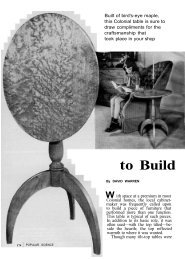
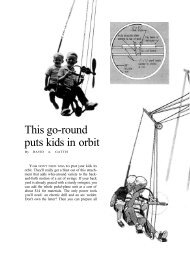
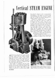
CHARGER WIRING SCHEMATIC<br />
12-V. BATTERY<br />
CHARGER<br />
COMPLETE ELECTRICAL WIRING SCHEMATIC FOR SIDEWALK CLASSIC<br />
CENTER-OFF TOGGLE SWITCH<br />
ACCELERATOR<br />
SWITCH D.P.S.T.<br />
N.O. PUSH<br />
BUTTON<br />
CHARGE GO<br />
OFF<br />
12-V. STORAGE<br />
BATTERY<br />
# 10 WIRE<br />
STANDARD SURFACE-<br />
MOUNTED UTILITY BOX BRAKE-LIGHT<br />
SWITCH S.P.S.T.-N.O.<br />
AUTO<br />
GENERATOR<br />
12-V. 30-AMP.<br />
CHARGER<br />
# 10<br />
# 16<br />
X TERMINAL<br />
NOT USED<br />
12-V. BATTERY<br />
# 10<br />
# 16<br />
- +<br />
12-V<br />
DC.<br />
OUT<br />
110-V. A.C.<br />
X SWITCH TERMINAL NOT USED<br />
CHARGE<br />
OFF<br />
GO<br />
SWITCH<br />
# 16 WIRE<br />
110-V. A.C.<br />
110-V.<br />
DC.<br />
IN STOP<br />
LIGHT<br />
BRAKE-LIGHT<br />
SWITCH<br />
110-V.+ -<br />
CHARGE-OFF-GO<br />
SWITCH. D.P.D.T.<br />
(BOTTOM VIEW)<br />
# 16<br />
WIRE<br />
ACCELERATOR<br />
SWITCH<br />
GEN.
Ready access to all electrical equipment—battery, motor, switch and charger—is made possible<br />
by <strong>the</strong> hinged seat, top and deck, which tilt forward. The seat is held down with a hook<br />
lea<strong>the</strong>r fabric, <strong>the</strong> pattern for which is given on<br />
page 509. Overall measurements before hemming<br />
are shown with <strong>the</strong> exception of one dimension,<br />
from <strong>the</strong> rear window opening to <strong>the</strong><br />
bottom of <strong>the</strong> back flap, which is given after<br />
hemming.<br />
Don't cut <strong>the</strong> fabric until after you have made<br />
and assembled <strong>the</strong> bows and braces. You can<br />
bend <strong>the</strong> center bow by hand, but you run <strong>the</strong><br />
risk of getting an uneven bend and spoiling <strong>the</strong><br />
contour of <strong>the</strong> roof as a result. Instead, borrow<br />
an electrician's conduit bender for this job.<br />
After bending, flatten at <strong>the</strong> points indicated and<br />
drill holes for <strong>the</strong> bolts. Then bend <strong>the</strong> front and<br />
back bows, flatten <strong>the</strong> ends slightly, and also<br />
drill <strong>the</strong> holes for <strong>the</strong> bolts.<br />
The holes in <strong>the</strong> front bow for <strong>the</strong> bolts that<br />
hold <strong>the</strong> upper end of <strong>the</strong> braces are located<br />
and drilled after a trial assembly.<br />
Now refer to <strong>the</strong> drawing on page 509 for<br />
<strong>the</strong> location of <strong>the</strong> holes for <strong>the</strong> bolts holding<br />
<strong>the</strong> center bow to <strong>the</strong> ends of <strong>the</strong> seat. Drill <strong>the</strong>se<br />
holes and mount <strong>the</strong> assembled bows temporarily<br />
so that you can more easily fit <strong>the</strong> fabric top.<br />
Lay <strong>the</strong> fabric over <strong>the</strong> bows and determine <strong>the</strong><br />
location of <strong>the</strong> pleats, or tucks, and <strong>the</strong> amount<br />
to be turned under for <strong>the</strong> hems. This done, sew<br />
The electricals are housed in <strong>the</strong> body, with <strong>the</strong> battery<br />
in a well under <strong>the</strong> seat. Note <strong>the</strong> position of <strong>the</strong><br />
charger and <strong>the</strong> "off-go-charge" switch. Note also <strong>the</strong><br />
use of snap-on terminal clamps on <strong>the</strong> battery<br />
511
The back drop, or flap, of <strong>the</strong> fabric top is attached<br />
to <strong>the</strong> back of <strong>the</strong> seat with storm-sash hangers. The<br />
rear window is fitted with a sheet of clear plastic<br />
<strong>the</strong> hems all around, making <strong>the</strong> pleats as you<br />
go. Cut <strong>the</strong> opening for <strong>the</strong> rear window. Cut<br />
thin, clear plastic about 1/2 in. larger all around<br />
than <strong>the</strong> opening and sew in place. After pleating<br />
and hemming, fold <strong>the</strong> forward end of <strong>the</strong><br />
fabric around <strong>the</strong> front bow and fasten with<br />
split rivets. Note that <strong>the</strong> lea<strong>the</strong>r straps are attached<br />
to <strong>the</strong> top with split rivets at <strong>the</strong> pleats<br />
and at <strong>the</strong> front edge of <strong>the</strong> fabric. Attach a<br />
The wiring from <strong>the</strong> foot-operated switch and <strong>the</strong><br />
stoplight switch is stapled to <strong>the</strong> underside of <strong>the</strong><br />
frame. Wire sizes are indicated on <strong>the</strong> schematic<br />
512<br />
swivel snap to <strong>the</strong> free end of each strap, fastening<br />
with split rivets.<br />
The back drop, or flap, of <strong>the</strong> top attaches<br />
to <strong>the</strong> back of <strong>the</strong> seat with three storm-sash<br />
hangers. Note that <strong>the</strong> sash half of <strong>the</strong> hanger<br />
is riveted to <strong>the</strong> lower edge of <strong>the</strong> fabric, while<br />
<strong>the</strong> o<strong>the</strong>r half of each hanger is attached to <strong>the</strong><br />
back of <strong>the</strong> seat with 10-24 screws and hex nuts.<br />
Note that when everything is assembled <strong>the</strong><br />
hinged seat, deck and top tip forward to give<br />
access to <strong>the</strong> electricals, motor, battery, charger<br />
and <strong>the</strong> off-run-charge switch. The exact location<br />
of <strong>the</strong> switch and charger is of no importance;<br />
place <strong>the</strong>m so <strong>the</strong>re is access to each.<br />
When wiring, follow <strong>the</strong> wiring diagram which<br />
gives <strong>the</strong> wire sizes to use. Wires from <strong>the</strong> startstop,<br />
foot-controlled switch and to <strong>the</strong> stoplight<br />
switch are stapled to <strong>the</strong> underside of <strong>the</strong> frame.<br />
Before making <strong>the</strong> test run, be sure you have<br />
<strong>the</strong> correct tension on <strong>the</strong> driving V-belt and that<br />
all nuts and screws have been properly tightened.<br />
The fifth, or spare, wheel pictured is optional.<br />
The carrier is simply a threaded 1/2-in. stud and<br />
shaft collar installed on <strong>the</strong> back body panel.<br />
Brackets for <strong>the</strong> headlights (<strong>the</strong> brackets come<br />
with <strong>the</strong> units) are screwed to <strong>the</strong> dashboard as<br />
shown.<br />
colors are optional<br />
Paint colors are optional. The original pictured<br />
was painted a bright red with a silver<br />
striping, an attractive combination. The top of<br />
<strong>the</strong> plywood frame was finished in natural color.<br />
The disk wheels were sprayed with silver paint.<br />
There are some interesting decorative touches<br />
that you can add which will increase <strong>the</strong> au<strong>the</strong>ntic<br />
look and at <strong>the</strong> same time make <strong>the</strong> car more<br />
fun to own. For example, if you shop around,<br />
you should b.e able to find one of those old<br />
rubber-bulb operated auto horns. If you can<br />
find one with a shiny brass bell, so much <strong>the</strong><br />
better.<br />
The same material you used to make <strong>the</strong> top<br />
would serve very well as a covering fabric if<br />
you chose to upholster <strong>the</strong> seats. You wouldn't<br />
have to be fancy. Just cover <strong>the</strong> wooden seat and<br />
back with 1 or 1.5-in. of foam rubber, cover with<br />
<strong>the</strong> fabric, <strong>the</strong>n tack to <strong>the</strong> edges of <strong>the</strong> seat. Use<br />
large-headed colored upholstery nails. For a<br />
final touch of au<strong>the</strong>nticity, drive some of <strong>the</strong>se<br />
nails into <strong>the</strong> back and <strong>the</strong> seat in a grid pattern,<br />
with about 6 in. between nails, to imitate<br />
<strong>the</strong> old upholstery buttons.<br />
See also: bicycles; cars, midget; stage coach; train,<br />
children's; unicycle.