SENSO–V flow volume indicator - Oppermann Regelgeräte GmbH
SENSO–V flow volume indicator - Oppermann Regelgeräte GmbH
SENSO–V flow volume indicator - Oppermann Regelgeräte GmbH

Create successful ePaper yourself
Turn your PDF publications into a flip-book with our unique Google optimized e-Paper software.
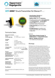
<strong>SENSO–V</strong> <strong>flow</strong> <strong>volume</strong> <strong>indicator</strong><br />
Technical data<br />
Housing: high impact ABS<br />
Front panel color: antique white<br />
Lower housing color: anthracite<br />
Protection class: IP 54<br />
with additional sealing<br />
(accessories) IP 64<br />
Operating temperature: -10 to +40 °C<br />
Storage temperature: -20 to +60 °C<br />
Relative humidity: max. 75 % non-condensing<br />
Housing dimensions: 112 x 58 mm [Ø x D]<br />
Front cover dimensions:<br />
- square: 184 x 139 x 20 mm [L x W x H]<br />
- round: 145 mm Ø<br />
Hose connection: inner diameter 5 - 6 mm<br />
Working range: 50 – 5000 Pa<br />
Display range: 0 – 99.999 m 3 /h, l/s, ft 3 /min<br />
Burst pressure: 75 kPa<br />
Protection class: II (IEC 60536)<br />
Tolerance: ≤ 1.5 %<br />
Long-term stability: ≤ ± 0.5 % FS/a<br />
Approvals (EMC): EN61000-6-1, EN6000-6-2<br />
EN61000-6-3, EN610002-6-4<br />
Battery type: 2 x AA 1.5<br />
Battery life: 3 to 4 years at 0 - 40 °C ambient<br />
temperature and battery capacity of<br />
2800 mAh<br />
Types:<br />
Square front cover V5000-00<br />
Round front cover V5000-01<br />
Working range<br />
50 – 5000 Pa, 0 – 100 %<br />
• Easy to read LCD display<br />
• Display of <strong>flow</strong> <strong>volume</strong> up to 99,999 with<br />
the following display units: m 3 /h, l/s, ft 3 /min<br />
• Limit displayed up to max. <strong>flow</strong> <strong>volume</strong><br />
• Flashing red light when set limit is exceeded<br />
• Programmable limit, K-factor and air density ρ<br />
• Power supply: 2 “AA” batteries 1.5 V which last<br />
for at least 3 years<br />
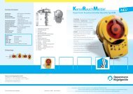
Design<br />
The SENSO-V consists of a round section and a square or round<br />
front cover. The instrument is optimized for installation in ventilation<br />
devices and control cabinets. The two pressure test points<br />
are sunk into the housing on the back and labeled with + (overpressure)<br />
and - (under pressure). There is a threaded sleeve in<br />
the middle. The retaining bracket is attached with the supplied<br />
threaded rod and wing nuts. The wing nuts are secured against<br />
loosening. The flange sealing of the functional part across from<br />
the mounting surface occurs with an integrated O-ring. There<br />
is an arrow on the device, pointing to the up side in order to<br />
ensure the vertical mounting position when being installed.<br />
Visible at the front, built into the functional part, there is a LCD<br />
display, an LED to indicate when limits are exceeded, 3 function<br />
keys. After installation and configuration of the device, the front<br />
cover is snapped onto the functional part. Due to 3 guided<br />
notches this is only possible in the correct position. Removing<br />
the front cover is done by pulling with both hands or by using a<br />
screwdriver.<br />
Sensor ventilation air conditioning | Data sheet No. 13155 | Version 02-2011 | 1 | 3
Activation and operation<br />
To activate the SENSO-V, the polarized power cable of the<br />
battery pack is plugged into the motherboard. With sufficient<br />
battery capacity, the device is immediately ready for operation<br />
<strong>indicator</strong>s on the LCD are active). Within the first 20 min. the<br />
measured values are renewed every 3 seconds after previously<br />
averaging over 5 measurements. After this, the average is<br />
shown only once every 2 min. With values below 50 Pa (model<br />
V5000) the display shows “LO”. The setting of the display unit<br />
(dimension), and the programming of the limit, occurs via the<br />
three keys available after removing the front cover.<br />
Setting display unit (dimension)<br />
A brief push of the lower key (S1) in normal operation switches<br />
the unit back and forth between m 3 /h, l/s and ft 3 /min.<br />
Programming the SENSO-V<br />
During programming, the current values on the display remain<br />
frozen.<br />
A prolonged pressing of the lower key (S1), gets you into the<br />
programming mode. The upper limit to be set starts flashing.<br />
By pushing the key (S1) again briefly, the menu items begin to<br />
change in the following order:<br />
Limit - K-factor - air density ρ<br />
If the corresponding display flashes, the individual values can<br />
be set with the top left key (S2) and the top right key (S3):<br />
Short pushes → single steps<br />
Long press → increases rate of change<br />
The lower limit in the selected unit is to be entered, the K-factor<br />
(manufacturer: measuring unit) and the air density, which is<br />
multiplied by 100 (default value 112 = 1.12 kg/m 3 ).<br />
When below the threshold, the LED flashes.<br />
Save (OK)<br />
If the key is not pressed for more than 5 seconds, the set values<br />
are saved automatically and the programming mode is exited.<br />
Battery capacity display<br />
Full: loading bar right down the full length of the battery<br />
Empty: no progress bar visible Change battery: in max.<br />
2 months, when the loading bar is visible in the right segment.<br />
To change batteries, pull the battery holder as it is inserted,<br />
from the holder itself, and change both batteries<br />
0-point adjustment<br />
Disconnect supply voltage. Then release pressure from the<br />
measuring inputs (remove both hoses).<br />
Push (S1) key and keep pressed.<br />
Apply supply voltage (→ display flashes).<br />
Release S1 key (→ pressure indicated: 0 Pa).<br />
2 | 3 | Sensor ventilation air conditioning | Data sheet No. 13155 | Version 02-2011<br />
<strong>SENSO–V</strong> <strong>flow</strong> <strong>volume</strong> <strong>indicator</strong><br />
Press S1 button briefly and let go again (→ value will be stored).<br />
Advanced calibration options available on request.<br />
Display of differential pressure for control purposes.<br />
By simultaneously pushing the top two buttons the measured<br />
differential pressure will be displayed in Pa for as long as the<br />
button remains pushed.<br />
Delivery:<br />
The standard version contains the functional part, the front<br />
cover and installation instructions.<br />
Accessories: SENSO-Z assembly kit, O-ring for IP 64 SENSO-D,<br />
Clima-set SENSO-CS, mounting rack for SENSO-H with a height<br />
of 30 or 50 mm.<br />
Principle of operation<br />
The measured differential pressure is guided over the connecting<br />
nipples with flexible hoses onto the piezoelectric differential<br />
pressure sensor, electronically evaluated and displayed on the<br />
LCD <strong>indicator</strong> with the programmed K-factor and the converted<br />
ρ density into <strong>flow</strong> <strong>volume</strong>.<br />
The calculation basis is the following basic formula:<br />
V h = K √<br />
2 x ∆p<br />
ρ<br />
Vh = <strong>flow</strong> rate [m³/h]<br />
K = K factor [m²s/h]<br />
∆p = differential pressure [Pa]<br />
ρ = air density [kg/m³]<br />
Note: Many fan manufacturers use simplified basic formulas<br />
and due to this modified K values. Therefore when entering<br />
the K-factor for the Senso, the formula of the manufacturer<br />
must always be taken into account.<br />
Examples of K-factors to be set on the Senso (K Senso):<br />
Ziehl-Abegg fan types: ER…C, GR…C, etc.:<br />
K Senso = 0,7746 x K Ziehl-Abegg<br />
Ebm-Pabst fans types: R3G, K3K, etc.:<br />
K Senso = 0,7746 x K Ebm-Pabst<br />
Fläkt fans types: CXLF, GXLB, GXHB, GPEB, etc.:<br />
K Senso = 2.788,5 / K Fläkt<br />
Gebhardt fans types: RZR, RZA, RZM, RLM, etc.:<br />
K Senso = K Gebhardt<br />
Non-binding information. Please note the current<br />
data sheets of the manufacturers. Subject to change.
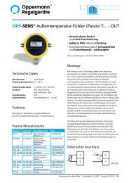
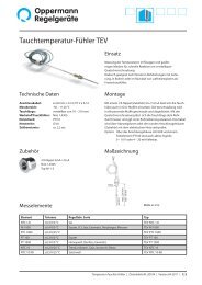
SENSO-V set<br />
Back view of SENSO-V<br />
Installation<br />
O-ring seal<br />
3 keys<br />
Diameter:<br />
Round front cover<br />
145 mm<br />
Mounting direction<br />
is at the top<br />
M6 threaded sleeve<br />
for fastening<br />
Wing nut<br />
In the sandwich plate or the cabinet door a 115 mm Ø hole is<br />
milled and the functional part is pushed through the opening<br />
from the front. The mounting direction is labeled with an arrow<br />
pointing upward on the back of the device. The threaded rod<br />
is screwed into the threaded sleeve with a screwdriver; the<br />
mount ing bracket is slipped over and secured with a wing nut.<br />
When assembling the pressure transfer hoses, care must be<br />
taken to comply with the direction of the pressure (+ pressure,<br />
- pressure). Now, the front panel can be snapped into place.<br />
The operating instructions are pasted onto the back side<br />
of the front cover.<br />
<strong>SENSO–V</strong> <strong>flow</strong> <strong>volume</strong> <strong>indicator</strong><br />
<strong>Oppermann</strong> <strong>Regelgeräte</strong> <strong>GmbH</strong> | Im Spitzhau 1 | 70771 Leinfelden-Echterdingen, Germany<br />
Phone +49 711 72723560 | Fax +49 711 7280527 | info@oppermann-regelgeraete.de | www.oppermann-regelgeraete.de<br />
Specifications subject to change. Sensor ventilation air conditioning | Data sheet No. 13155 | Version 02-2011 | 3 | 3