41302_en - Oppermann Regelgeräte GmbH
41302_en - Oppermann Regelgeräte GmbH
41302_en - Oppermann Regelgeräte GmbH

You also want an ePaper? Increase the reach of your titles
YUMPU automatically turns print PDFs into web optimized ePapers that Google loves.
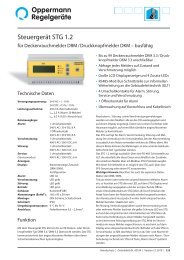
Duct Smoke S<strong>en</strong>sor KRM®-DZ<br />
Technical Data<br />
<strong>Oppermann</strong><br />
<strong>Regelgeräte</strong><br />
<strong>GmbH</strong><br />
Z-78.6-200<br />
VdS<br />
S<strong>en</strong>sor: Scattering RM 3.3 (ALK-E)<br />
Supply voltage KRM-1-DZ:<br />
230 V AC ± 10 %, 50 / 60 Hz<br />
Supply voltage KRM-2-DZ / KRM-2-DZ-MOD:<br />
24 V AC / DC +15 % / -10 %<br />
Rated curr<strong>en</strong>t: KRM-1-DZ: 30 mA<br />
KRM-2-DZ / KRM-2-DZ-MOD: 140 mA<br />
Relay outputs: fl oating<br />
Alarm relay locked: 1 changeover contact, 8 A,<br />
250 V AC or 24 V DC<br />
1 NC, 8 A, 250 V AC or 24 V DC<br />
Contamination relay: 1 NC contact, 6 A, 250 V AC or 24 V DC<br />
System failure relay: 1 NC contact, 6 A, 250 V AC or 24 V DC<br />
Air fl ow relay: 1 NC contact, 6 A, 250 V AC or 24 V DC<br />
Operating temperature: -15 °C – +50 °C<br />
Permissible humidity: 10 – 95 % non-cond<strong>en</strong>sing<br />
Protection class: IP 54, IP 65 with WDG<br />
(water resistant housing)<br />
Approvals:<br />
S<strong>en</strong>sing chamber and<br />
air duct frames: DIBt approval Z-78.6-200<br />
VdS certifi cation G210148<br />
Tested: according to FprEN54-27<br />
LED display: % contamination level fl ashes at > 70 %<br />
LED in housing: gre<strong>en</strong> operating<br />
blue lack of air fl ow<br />
yellow failure, electronics,<br />
smoke detector defective,<br />
low voltage<br />
red smoke alarm, including<br />
contamination > 99 %,<br />
fl ashes at attempts to release<br />
wh<strong>en</strong> the s<strong>en</strong>sing chamber is<br />
not empty<br />
Adapter housing: ABS<br />
Air measuring tube: Aluminium / plastic<br />
shortest l<strong>en</strong>gth 160 mm<br />
standard l<strong>en</strong>gth 600 mm<br />
Dim<strong>en</strong>sions: 257 x 166 x 77 mm (L x W x H)<br />
Screw connection: 3 x M16<br />
• DIBt approval No. Z-78.6-200 for control of<br />
fi re/smoke protection fl aps<br />
• VdS certifi cation (G210148)<br />
• Pat<strong>en</strong>ted single tube air sampling system<br />
• Contamination display in % and<br />
signalling at 100 %<br />
• Electronic air fl ow control<br />
• Externally operable reset button in the housing<br />
• Remote reset option via terminals<br />
• Long service life, low contamination<br />
• Annual service interval<br />
Accessories<br />
Mounting bracket: KS (for insulated / circular ducts)<br />
KS-WDG (for insulated / circular ducts in<br />
combination with WDG)<br />
Housing: WDG – waterresistant housing for<br />
outdoor installation and increasing<br />
protection class to IP 65<br />
Function<br />
The KRM-DZ duct smoke detector is designed for smoke<br />
detection in v<strong>en</strong>tilation ducts. It constitutes a combination of a<br />
smoke detector with an adapter system, whose measuring tube<br />
and housing have be<strong>en</strong> specially adapted for optimal air fl ow<br />
through the smoke detector.<br />
The air duct sampling tube transports the air within the air<br />
duct along the <strong>en</strong>tire l<strong>en</strong>gth of the tube, through the s<strong>en</strong>sing<br />
chamber and back into the air duct. Upon detection of smoke,<br />
the s<strong>en</strong>sor reacts immediately and triggers an alarm. Over time,<br />
the s<strong>en</strong>sor becomes contaminated. Because of alarm threshold<br />
tracking, the s<strong>en</strong>sitivity up to total pollution remains the same.<br />
From 70 % contamination upwards, the s<strong>en</strong>sor is triggered and<br />
signals a fault. If the s<strong>en</strong>sor is not replaced the smoke alarm is<br />
triggered at 99 % contamination. The contamination level is<br />
indicated in a two-line LED display; at > 70 % it fl ashes.<br />
To verify operability, the device is equipped with electronic air<br />
fl ow monitoring, which lights a blue LED at < 1 m/s. The failure<br />
LED illuminates wh<strong>en</strong> the smoke s<strong>en</strong>sor or the electronics are<br />
defective, in the abs<strong>en</strong>ce of a smoke s<strong>en</strong>sor, and with shortcircuits<br />
or cable breakage.<br />
The smoke alarm must be released with the reset button. A<br />
functionality test is also possible with the same button. The<br />
operation functions like a smoke alarm. Furthermore, the<br />
same function takes place on restart or wh<strong>en</strong> the bridge circuit<br />
betwe<strong>en</strong> terminals 9 and 10 is op<strong>en</strong>ed (remote release).<br />
Fire Protection | Data sheet No. <strong>41302</strong> | Version 01-2012 | 1 | 11
Electrical connection<br />
KRM-1-DZ<br />
Supply voltage<br />
230 V ~ 50 – 60 Hz<br />
230 V<br />
Op<strong>en</strong><br />
Closed<br />
M<br />
Smoke alarm<br />
Individual<br />
contact<br />
Fire/smoke protection fl ap<br />
230 V AC<br />
1<br />
2<br />
3<br />
4<br />
9<br />
10<br />
11<br />
12<br />
13<br />
14<br />
15<br />
16<br />
17<br />
18<br />
19<br />
20<br />
21<br />
Power supply<br />
230 V AC<br />
Test/Reset (NC contact)<br />
KRM-1-DZ<br />
Smoke alarm<br />
Smoke alarm<br />
Service signal<br />
contamination<br />
Service signal<br />
system failure<br />
Service signal<br />
air flow<br />
Test/Reset<br />
All contact depictions are with the power off (alarm) / no air fl ow pres<strong>en</strong>t.<br />
For wiring KRM-2-DZ-MOD see KRM-2-DZ (next page).<br />
Remote reset/test (terminal 9 +10): if bridge circuit is removed, a fl oating NC contact must be connected.<br />
gre<strong>en</strong><br />
yellow<br />
blue<br />
2 | 11 | Fire Protection | Data sheet No. <strong>41302</strong> | Version 01-2012<br />
14<br />
11<br />
9<br />
10<br />
red<br />
13<br />
12<br />
KRM-2-DZ-MOD<br />
Duct Smoke S<strong>en</strong>sor KRM-DZ<br />
1 Adapter plate with gasket<br />
2 Pat<strong>en</strong>ted measuring tube (max. l<strong>en</strong>gth 3 m)<br />
3 End cap<br />
4 Rubber bushing<br />
(only for insulated or circular ducts)<br />
5 Lower housing with seal<br />
6 Electronics<br />
7 Optical smoke s<strong>en</strong>sor<br />
8 Upper casing with seal<br />
9 Red LED: alarm / reset button<br />
10 Yellow LED: interfer<strong>en</strong>ce<br />
11 LED display: % of s<strong>en</strong>sor contamination<br />
12 LED gre<strong>en</strong>: in operation<br />
13 LED blue: air fl ow under 1 m / s<br />
14 Op<strong>en</strong>ing for test gas<br />
15 Air duct<br />
Supply voltage<br />
24 V AC / DC<br />
Test / Reset<br />
(NC contact)<br />
Notes: The fl oating switching contacts (terminals 11 – 21) are uniformly assigned to an installation category according to EN 60730-1.<br />
These switching contacts are only to be used for 230 V AC or 24 V AC/DC, a combination is not permitted.<br />
A mixed connection of safety extra-low voltage (SELV) and low voltage must not occur. The assembly may only be operated on one mains<br />
phase. The voltage / safeguard activation is to be provided on site. KRM-1-xx (230 V versions) with a fuse of 16 A; KRM-2-xx (24 V version)<br />
with 4 A.<br />
1<br />
2<br />
3<br />
4<br />
5<br />
6<br />
7<br />
8<br />
9<br />
10<br />
11<br />
12<br />
13<br />
14<br />
15<br />
16<br />
17<br />
18<br />
19<br />
20<br />
21<br />
Bus B<br />
Bus B<br />
Bus A<br />
Bus A<br />
Power supply<br />
24 V AC/DC<br />
RS 485 Mod-Bus<br />
(informative)<br />
Smoke alarm<br />
Smoke alarm<br />
Service signal<br />
contamination<br />
Service signal<br />
system failure<br />
Service signal<br />
air flow<br />
KRM-2-DZ-MOD<br />
Test/Reset<br />
gre<strong>en</strong><br />
yellow<br />
Programming the Bus address for the KRM-2-DZ-MOD:<br />
Press buttons T3+T4 on the circuit board (to the right, next to the display) at the same<br />
time, so that the display changes from contamination level to show the bus address (the<br />
display will fl ash). Press button T3 or T4 to adjust the desired address (1 – 99). The last<br />
set bus address is automatically saved. The display resets automatically after 3 seconds<br />
or by simultaneously pressing T3+T4.<br />
blue<br />
red
Duct Smoke S<strong>en</strong>sor KRM-DZ<br />
Wiring diagram, fire protection flap/Smoke protection flap 24 V DC or 24 V AC<br />
All contact depictions in the following images are with the power off (alarm)/ with no airflow.<br />
1. Connection to BSK/RSK (with external voltage 24 V AC/DC) – triggering with KRM-1-DZ<br />
KRM-1-DZ<br />
* On-site secured supply voltage 24 V AC/DC for the BSK/RSK<br />
2. Connection to BSK/RSK (24 V AC/DC) - triggering and power supply with KRM-2-DZ/KRM-2-DZ-MOD<br />
KRM-2-DZ /<br />
KRM-2-DZ-MOD<br />
Fire Protection | Data sheet No. <strong>41302</strong> | Version 01-2012 | 3 | 11
Display and operation for Duct Smoke S<strong>en</strong>sor KRM<br />
Display Meaning Comm<strong>en</strong>ts<br />
00 – 99<br />
Start / calibration<br />
Contamination<br />
in %<br />
Failure<br />
4 | 11 | Fire Protection | Data sheet No. <strong>41302</strong> | Version 01-2012<br />
Duct Smoke S<strong>en</strong>sor KRM-DZ<br />
LED Smoke alarm (red) LED Smoke alarm (red)<br />
LED Failure (yellow) LED Power supply<br />
(gre<strong>en</strong>)<br />
LED Alarm (red) and<br />
Alarm / reset button<br />
Failure reset:<br />
Briefl y press button and release<br />
Alarm reset:<br />
Press button for at least 2 seconds<br />
until the red LED goes out<br />
+<br />
all LEDs on the<br />
circuit board<br />
light up<br />
00 – 99<br />
fl ashing<br />
Confi rmation<br />
reset / new start<br />
BUS adresse<br />
Shortly after starting the software version is displayed (4 digits),<br />
e.g. 00 th<strong>en</strong> 17 = Software 0017.<br />
Thereafter, the rotating segm<strong>en</strong>t display follows at startup or after a power failure.<br />
Flashes starting at 70 %; at 99 % with display LED alarm.<br />
Display indicator<br />
(contamination in % or status)<br />
LED Air fl ow (blue)<br />
lights up wh<strong>en</strong> there is insuffi ci<strong>en</strong>t fl ow<br />
e.g. Missing smoke detector, disrupted communication with the smoke detector,<br />
processor failure.<br />
Failure LED & alarm LED light up at the same time (not on the DIBt version).<br />
Troubleshooting: Change the detector and confi rm by pressing the alarm / reset button.<br />
If alarm / reset button is pressed for more than 8 seconds, or if bridge circuit / terminal<br />
9 / 10 is op<strong>en</strong> (missing bridge circuit or remote reset). Display goes out after releasing the<br />
alarm / reset button or closing the bridge circuit betwe<strong>en</strong> terminal 9 + 10.<br />
Display only with MOD versions after pressing the address buttons T3 / T4 directly on the<br />
circuit board.
LEDs Meaning Comm<strong>en</strong>ts<br />
Reset after failure:<br />
Briefly press alarm / reset button. KRM immediately restarts.<br />
Alarm / reset<br />
(red)<br />
Failure<br />
(yellow)<br />
Smoke alarm<br />
(2 x red)<br />
Power<br />
(gre<strong>en</strong>)<br />
Air flow<br />
(blue)<br />
Smoke alarm or<br />
failure (not on<br />
the DIBt version)<br />
Defective circuit<br />
board or missing<br />
smoke alarm<br />
Smoke alarm<br />
or contamination<br />
99 %<br />
Supply voltage<br />
is on<br />
Air flow is too<br />
low<br />
DIBt versions<br />
KRM-1-DZ / KRM-2-DZ<br />
KRM-2-DZ-MOD<br />
Installation Instructions and Positioning<br />
The KRM is to be positioned in accordance with the curr<strong>en</strong>t<br />
local state regulations on v<strong>en</strong>tilation systems. Reliable smoke<br />
detection must be guaranteed. Dep<strong>en</strong>ding on the cross section<br />
of the v<strong>en</strong>tilation duct the air collecting tube may be cut to a<br />
l<strong>en</strong>gth of 160 mm. This minimum l<strong>en</strong>gth of 160 mm must not<br />
be undercut. This way, up to
In the ideal case, install the KRM wh<strong>en</strong> structurally possible,<br />
where fl ow meters, etc. are normally attached, so there is a laminar<br />
airfl ow along the measuring tube. We recomm<strong>en</strong>d that the<br />
KRM be fi tted and installed at the same distance from heating,<br />
cooling and humidity devices as fl ow s<strong>en</strong>sors. The distance of<br />
the KRM to fi ttings, valves, fi lters, etc. in terms of fl ow direction<br />
should be 3 times, and in the diagonal direction 5 times<br />
that of the cross-section, if this structurally possible. The KRM<br />
including the air collecting tube may not be installed along the<br />
longitudinal edges of v<strong>en</strong>tilation ducts (corner area). The KRM<br />
is to be installed so that the air collecting tube is constantly in<br />
the air stream. In horizontal v<strong>en</strong>tilation ducts the KRM including<br />
air collecting tube should be installed in the upper third of the<br />
v<strong>en</strong>tilation ducts or at the top of the v<strong>en</strong>tilation ducts, if this is<br />
structurally possible.<br />
Wh<strong>en</strong>, for structural reasons, the recomm<strong>en</strong>ded positioning is<br />
not possible, the KRM is to be mounted so that, nonetheless, a<br />
reliable smoke detection/fl ow is <strong>en</strong>sured. The blue LED “Airfl ow”<br />
may be used as an indicator of a suffi ci<strong>en</strong>t fl ow (the LED is off<br />
with suffi ci<strong>en</strong>t fl ow).<br />
Hydraulic diameter d h<br />
Round duct<br />
d h =D<br />
Example of positioning<br />
after the change of<br />
air duct direction. (Recomm<strong>en</strong>dation)<br />
5 d h<br />
MIN 3xd<br />
h<br />
MIN 5xd<br />
h MIN 3xd<br />
h<br />
MIN 5xd<br />
h<br />
KRM<br />
KRM KRM<br />
KRM<br />
KRM<br />
3 d h<br />
MIN 3xd h<br />
MIN 5xd<br />
h<br />
MIN 3xd<br />
h MIN 5xd<br />
h<br />
MIN 5xd<br />
h<br />
KRM KRM KRM<br />
KRM<br />
Change in air<br />
KRM<br />
MIN 5xd<br />
h<br />
Air duct narrowing/<br />
duct direction Air duct forking Air duct <strong>en</strong>largem<strong>en</strong>t<br />
MIN 3xd h<br />
øD<br />
MIN 3xd h<br />
Rechtangular duct<br />
d h = 2xHxB<br />
H+B<br />
Example of positioning (Recomm<strong>en</strong>dation)<br />
6 | 11 | Fire Protection | Data sheet No. <strong>41302</strong> | Version 01-2012<br />
KRM<br />
Air outlet<br />
Duct Smoke S<strong>en</strong>sor KRM-DZ<br />
Follow these instructions. All work (such as installation, electrical<br />
connection, start-up, operation and maint<strong>en</strong>ance), must<br />
be carried out by suffi ci<strong>en</strong>tly qualifi ed craftsman. Curr<strong>en</strong>t local<br />
rules and regulations (e.g. building regulations, elecrical/VDE<br />
guidelines, etc.) are to be observed. Installers and operators are<br />
required to be adequately informed before operation. Read the<br />
product description before device start-up. Make sure that the<br />
product is fully suited to the respective applications. We assume<br />
no liability for misprints and changes after printing. Compliance<br />
with operating and installation instructions is also included<br />
within the regulations of int<strong>en</strong>ded use. We assume no liability<br />
for damages caused by improper use. Operating lic<strong>en</strong>ses and<br />
guarantees and all warranty claims will be voided in the ev<strong>en</strong>t<br />
of unauthorized modifi cations or any tampering with the<br />
device..<br />
5 d h<br />
MIN 5xd<br />
h<br />
MIN 3xd MIN 5xd<br />
h h<br />
KRM KRM<br />
KRM<br />
V<strong>en</strong>tilator Air�ap Mu�er Battery<br />
H<br />
B<br />
MIN 3xd<br />
h<br />
KRM<br />
KRM<br />
MIN 5xd<br />
h Exhaust air<br />
Supply air<br />
Air duct device<br />
Example of positioning<br />
after air outlets (Recomm<strong>en</strong>dation)<br />
Where there are large temperature di�er<strong>en</strong>ces,<br />
outdoors for example, or in places that are<br />
dep<strong>en</strong>d<strong>en</strong>t on outside temperature (roof, attic),<br />
the air duct smoke s<strong>en</strong>sor has to be insulated.<br />
For this <strong>Oppermann</strong> <strong>Regelgeräte</strong> provides<br />
a special splash-proof housing (WDG).
Installation<br />
1.<br />
Drill a hole 43 – 44 mm in diameter at the int<strong>en</strong>ded mounting<br />
location.<br />
Note: Installation of the TurboTube measuring tube is possible either<br />
from the top, bottom or side of the channel for all duct<br />
cross-sections (for round ducts as well).<br />
2.<br />
• Determine how long the measuring tube must be.<br />
• If necessary, short<strong>en</strong> the tube. Minimum l<strong>en</strong>gth 160 mm.<br />
• Deburr the cutting face and put the <strong>en</strong>d plug back on up to the<br />
stop collar.<br />
Note: dep<strong>en</strong>ding on delivery batch, either the transpar<strong>en</strong>t <strong>en</strong>d caps<br />
displayed here or black <strong>en</strong>d caps with a slightly diff er<strong>en</strong>t geometry will<br />
be included in the delivery.<br />
3.<br />
• Determine the direction of fl ow and fi t the adapter plate so that<br />
the line on the adapter plate under the text ”Strömungsrichtung”<br />
is parallel to the fl ow direction.<br />
• Four self-tapping screws serve for attaching it to the sheet metal<br />
duct (not included in delivery).<br />
4. Installation on a rectangular air duct<br />
• see picture at right<br />
5. Installation on a circular air duct<br />
• For mounting on a circular air duct use mounting bracket type KS<br />
and the rubber bushing �. Thanks to the b<strong>en</strong>d<br />
perforations they can be adapted to a round duct.<br />
The type KS mounting<br />
bracket is supplied fl at.<br />
6. Installation on air ducts with insulation<br />
• Use the rubber bushing and insert it into the Ø 43 – 44 mm<br />
op<strong>en</strong> ing in the air duct.<br />
• Install the mounting bracket.<br />
• Insert the assembled adapter plate into the measuring tube by<br />
sliding the measuring tube through the grommet, and screw the<br />
adapter plate onto the mounting bracket using the 4 self-tapping<br />
screws. Th<strong>en</strong> the insulation can be installed.<br />
7. Installation outdoors or in a cold <strong>en</strong>vironm<strong>en</strong>t<br />
• As protection for smoke detectors which are exposed to the op<strong>en</strong><br />
air or in a cold <strong>en</strong>vironm<strong>en</strong>t there is a special WDG type splashproof<br />
housing. This <strong>en</strong>closure prev<strong>en</strong>ts the warm air in the smoke<br />
detector duct from cond<strong>en</strong>sing. The interior of the housing is<br />
insulated with foam rubber.<br />
min. 160 mm<br />
Duct Smoke S<strong>en</strong>sor KRM-DZ<br />
Mounting<br />
bracket<br />
Rubber bushing<br />
inner<br />
Att<strong>en</strong>tion: Operation without<br />
<strong>en</strong>d plug not permitted.<br />
outer<br />
Mounting bracket Insulation<br />
Fire Protection | Data sheet No. <strong>41302</strong> | Version 01-2012 | 7 | 11
8. Installing the housing with the s<strong>en</strong>sor<br />
• Attach the housing bottom part with the electronics and s<strong>en</strong>sor to<br />
the adapter plate. The housing can be attached at increm<strong>en</strong>ts of<br />
90°. The direction of the housing has no effect on the measurem<strong>en</strong>t<br />
result. You can align the housing with the s<strong>en</strong>sor optimally.<br />
• Check that the seals in the housing upper part are correctly<br />
positioned.<br />
• By snapping on and tight<strong>en</strong>ing the upper housing and th<strong>en</strong> firmly<br />
pressing down on the arrow marked on the c<strong>en</strong>tral cable area (to<br />
<strong>en</strong>sure that the catch at the lower <strong>en</strong>d of the housing snaps in correctly),<br />
the mounting is complete.<br />
• Wire the unit according to the applicable circuit diagram.<br />
• Att<strong>en</strong>tion: wiring and electrical connections may only be carried<br />
out by a qualified electrician.<br />
• The cable jacket for field wire connecting must be done as near as<br />
possible to the terminal block. For wire without jacket longer as<br />
10 mm the wire must be fix by a cable clip near the terminal block.<br />
The pot<strong>en</strong>tial-free switching contacts are to be uniformly classified<br />
in one installation category according to EN 60730-1. The switch<br />
contacts are only to be used for 230 V AC or 24 V AC/DC; no combination<br />
thereof is permitted. There must not be a mixed connection<br />
of safety extra-low voltage (SELV) and low voltage. The compon<strong>en</strong>t<br />
may only be operated on one mains phase.<br />
9. Testing the duct smoke s<strong>en</strong>sor<br />
• After completing the installation work, doing proper wiring<br />
(please note the separate data sheets / circuit diagrams) and<br />
applying power, the duct smoke s<strong>en</strong>sor is operational.<br />
• The gre<strong>en</strong> LED (12) illuminates.<br />
• By pressing the alarm / reset button (9), an initial simple functional<br />
test can be made. All LEDs must light up and all the relays<br />
drop out. The units connected to the relays are activated! The<br />
display (11) indicates the curr<strong>en</strong>t degree of s<strong>en</strong>sor contamination.<br />
If the button is released, all LEDs will go out except for LED (12)<br />
which shows the supply voltage, and the relays activate.<br />
• For testing the smoke s<strong>en</strong>sor the housing must not be op<strong>en</strong>ed. It<br />
has a self-closing test op<strong>en</strong>ing (14) in the c<strong>en</strong>ter of the transpar<strong>en</strong>t<br />
cover. Use <strong>Oppermann</strong> test gas spray. Insert the test spray‘s<br />
tube fully into the test op<strong>en</strong>ing (appx. 1.5mm deep) and release<br />
as much test gas as needed until the smoke s<strong>en</strong>sor activates.<br />
Please do not spray too much, otherwise the smoke s<strong>en</strong>sor may<br />
display a higher degree of contamination at the next start / reset.<br />
The alarm / reset button lights up, the relays drop out. The electronics<br />
are on alert and locked. To release, the alarm / reset button<br />
must be pressed. At the time of the reset, the s<strong>en</strong>sor must be<br />
free of smoke and test gas. Should there still be test gas in the<br />
chamber a higher degree of contamination will appear. In this<br />
case, after some time perform a reset by disconnecting from the<br />
power or by an external reset, or if necessary, remove the housing<br />
cover and blow out the smoke detector.<br />
8 | 11 | Fire Protection | Data sheet No. <strong>41302</strong> | Version 01-2012<br />
Application example:<br />
Duct Smoke S<strong>en</strong>sor KRM-DZ<br />
10. Final review<br />
• Are all screws tight?<br />
• Is the adapter plate properly mounted for the<br />
flow direction?<br />
• Are all seals in the correct position?<br />
• In operation, wh<strong>en</strong> air flow > 1 m / s the blue<br />
LED may not light up.
Maint<strong>en</strong>ance and repair<br />
1. Instructions for operation and<br />
maint<strong>en</strong>ance<br />
The operator is responsible for the safe function of the v<strong>en</strong>tilation<br />
system. He has to <strong>en</strong>sure that the smoke s<strong>en</strong>sors are always<br />
ready for operation and that they are maintained, including all<br />
controlling compon<strong>en</strong>ts and systems. In order to <strong>en</strong>sure good<br />
performance over a longer period of time the smoke alarms<br />
must be tested at least once a year. Without maint<strong>en</strong>ance,<br />
and dep<strong>en</strong>ding on <strong>en</strong>vironm<strong>en</strong>tal conditions, the s<strong>en</strong>sor will<br />
become dirty sooner or later, and after a certain time will trigger<br />
an alarm, which is a false alarm.<br />
All types will give a specific maint<strong>en</strong>ance requirem<strong>en</strong>t<br />
signal at a contamination level of 70 % (display flashes).<br />
Targeted maint<strong>en</strong>ance can be carried out since the smoke<br />
detector is equipped with a 2-digit digital contamination<br />
indicator. From a 70 % contamination level or higher the smoke<br />
s<strong>en</strong>sor must be changed. There is a contact available for this<br />
“contamination” signal, and it should be connected to the automation<br />
station.<br />
2. Maint<strong>en</strong>ance and repair work<br />
Before starting with the maint<strong>en</strong>ance work, the functional<br />
integrity of the unit wh<strong>en</strong> it is exposed to smoke must be clarified<br />
with the staff. If, due to operational specifications shortterm<br />
shutdowns cannot be tolerated, measures must be tak<strong>en</strong><br />
to prev<strong>en</strong>t this; if necessary by placing a bridge over the alarm<br />
contact, but remembering to remove it after completion of the<br />
service work. After maint<strong>en</strong>ance work, a complete functionality<br />
test of all plant parts must be carried out. If defects have<br />
appeared they must be removed immediately. A protocol must<br />
be made after all maint<strong>en</strong>ance work and the results are to be<br />
writt<strong>en</strong> into the operation manual, which is to be signed by the<br />
operator in charge.<br />
Duct Smoke S<strong>en</strong>sor KRM-DZ<br />
Caution:<br />
Before op<strong>en</strong>ing the housing, unlock all supply voltages – The<br />
housing may only be op<strong>en</strong>ed by a qualified electrician. Supply<br />
and switching voltages must be observed.<br />
Please note the symbols on the device:<br />
Caution voltage<br />
Before working on equipm<strong>en</strong>t, turn voltage off<br />
Please follow the instructions<br />
The following work is required and can only be carried out by us<br />
or by our authorized experts:<br />
1. The smoke detector is accessible by removing the cover.<br />
2. By turning the detector on the base by about 20 °C to the<br />
left the s<strong>en</strong>sor can be unscrewed, and dirt and dust can be<br />
removed. If it is too dirty (indicator >70 %), the s<strong>en</strong>sor must<br />
be removed and exchanged for a new s<strong>en</strong>sor.<br />
3. Also to be cleaned:<br />
• the cover<br />
• the TurboTube measuring tube<br />
• the inner housing<br />
Fire Protection | Data sheet No. <strong>41302</strong> | Version 01-2012 | 9 | 11
4. Check the electrical connections, possibly tight<strong>en</strong>ing the<br />
terminals. Make visual inspection and clean the electrical<br />
circuit board if necessary, as well as the inner housing. Check<br />
all seals.<br />
5. Assemble all parts<br />
6. Test system by triggering the smoke detector with <strong>Oppermann</strong><br />
Test Spray.<br />
3. For DIBt approved smoke s<strong>en</strong>sors<br />
type KRM-1-DZ / KRM-2-DZ/<br />
KRM-2-DZ-MOD the following<br />
additional work is necessary<br />
1. Check contamination signal through carefully and specifically<br />
aimed test spray. The number in the display must increase<br />
and begin flashing at 70 %. Relays for contamination (terminal<br />
16 / 17) must op<strong>en</strong>. In addition, at 99 % the smoke alarm<br />
occurs.<br />
2. Check airflow monitoring. If the flow rate falls below 1.0 m / s,<br />
the blue LED illuminates. Air stream relay (terminal 20 / 21)<br />
must op<strong>en</strong>.<br />
3. Check system failure. With the removal of the smoke s<strong>en</strong>sor<br />
in the ev<strong>en</strong>t of short circuits or cable breaks and defective<br />
electronics, alarm relay drops off, the yellow light comes on.<br />
Control panel relay (terminal 18 / 19) must op<strong>en</strong>.<br />
4. Check the working coordination of all compon<strong>en</strong>ts with<br />
a functional test. This is part of the building inspection<br />
approval. By triggering the smoke s<strong>en</strong>sor with our test spray<br />
the two red LEDs light up, and on the circuit board the LED<br />
”alarm / reset” lights up in red as well. Relay and changeover<br />
smoke alarm (terminals 14 / 15 and 11 / 13) must op<strong>en</strong>. The<br />
BSK closes by spring return.<br />
10 | 11 | Fire Protection | Data sheet No. <strong>41302</strong> | Version 01-2012<br />
Duct Smoke S<strong>en</strong>sor KRM-DZ<br />
7. Check with the operator about the function of the downstream<br />
systems and compon<strong>en</strong>ts, such as:<br />
• Turning off of fans<br />
• Closing of flaps<br />
• Notification to the building automation system<br />
• Wh<strong>en</strong> checking network failure and recovery, does the<br />
s<strong>en</strong>sor return to its normal function and does it unlock<br />
again from the state ”smoke alarm” and return to its normal<br />
function wh<strong>en</strong> there is no longer any pres<strong>en</strong>t?<br />
• Release is possible by pressing the reset button (types:<br />
KRM-1-DZ, KRM-2-DZ and KRM-2-DZ-MOD) or with<br />
brief power interruptions (only for types KRM-1, KRM-2,<br />
KRM-2-MOD)<br />
• Release and approve for operation.<br />
5. Checking the operation after power failure: After power<br />
failure and recovery the smoke s<strong>en</strong>sor is set back into its state<br />
before the power failure. Both states; ”normal operation” and<br />
”smoke alarm” are to be checked after disconnection from the<br />
power supply. The reset can only be made after the failure<br />
and / or alarm has be<strong>en</strong> corrected.<br />
6. Malfunctions should be eliminated immediately.<br />
7. Register the results of the maint<strong>en</strong>ance in an operations<br />
manual.
7<br />
50<br />
Dim<strong>en</strong>sions<br />
40<br />
37.3<br />
77<br />
70<br />
166<br />
L= min. 160 mm<br />
50<br />
40<br />
37.3<br />
70<br />
166<br />
233<br />
24<br />
L= min. 160 mm<br />
Duct Smoke S<strong>en</strong>sor KRM-DZ<br />
<strong>Oppermann</strong> <strong>Regelgeräte</strong> <strong>GmbH</strong> | Im Spitzhau 1 | 70771 Leinfeld<strong>en</strong>-Echterding<strong>en</strong>, Germany<br />
Phone +49 711 72723560 | Fax +49 711 7280527 | info@oppermann-regelgeraete.de | www.oppermann-regelgeraete.de<br />
Subject to change. Fire Protection | Data sheet No. <strong>41302</strong> | Version 01-2012 | 11 | 11<br />
233<br />
24<br />
Dim<strong>en</strong>sions in mm
110<br />
Drilling template<br />
Dim<strong>en</strong>sions in mm<br />
166<br />
4<br />
44<br />
83<br />
233<br />
~260