Short catalogue – price list 2012 - Oppermann Regelgeräte GmbH
Short catalogue – price list 2012 - Oppermann Regelgeräte GmbH
Short catalogue – price list 2012 - Oppermann Regelgeräte GmbH

You also want an ePaper? Increase the reach of your titles
YUMPU automatically turns print PDFs into web optimized ePapers that Google loves.
<strong>Short</strong> <strong>catalogue</strong> <strong>–</strong> <strong>price</strong> <strong>list</strong> <strong>2012</strong>
<strong>Oppermann</strong> <strong>Regelgeräte</strong> <strong>GmbH</strong><br />
Im Spitzhau 1, 70771 Leinfelden-Echterdingen, Germany<br />
Phone +49 711 727235-60 info@oppermann-regelgeraete.de<br />
Fax +49 711 7280527 www.oppermann-regelgeraete.de<br />
General management<br />
Brigitta <strong>Oppermann</strong><br />
Phone +49 711 727235-60<br />
b.oppermann@oppermann-regelgeraete.de<br />
Heike Dirmeier<br />
Phone +49 711 727235-60<br />
dirmeier@oppermann-regelgeraete.de<br />
Managing Director Finance & Sales<br />
Dierk Astfalk<br />
Phone +49 711 727235-72<br />
astfalk@oppermann-regelgeraete.de<br />
Managing Director Technology<br />
Technical internal service and sales<br />
Raik Lehnacker<br />
Phone +49 711 727235-64<br />
lehnacker@oppermann-regelgeraete.de<br />
Internal sales service<br />
Internal sales manager<br />
Karin Haupt<br />
Phone +49 711 727235-63<br />
haupt@oppermann-regelgeraete.de<br />
Gas/CO warning devices<br />
Yvonne Pfau<br />
Phone +49 711 727235-69<br />
pfau@oppermann-regelgeraete.de<br />
District, postal code: 0, 1, 2, Export<br />
Sabine Görick<br />
Phone +49 711 727235-65<br />
goerick@oppermann-regelgeraete.de<br />
District, postal code: 8<br />
Sibylle Heider<br />
Phone +49 711 727235-66<br />
heider@oppermann-regelgeräte.de<br />
District, postal code: 3, 9, Export<br />
Gabriele Smith<br />
Telefon +49 711 727235-78<br />
smith@oppermann-regelgeraete.de<br />
District, postal code: 3, 4, 5, 6,7<br />
Franciska Pernat<br />
Phone +49 711 727235-67<br />
pernat@oppermann-regelgeraete.de<br />
<strong>Short</strong> <strong>catalogue</strong> | Price <strong>list</strong> <strong>2012</strong>-3<br />
Sales management<br />
Michael Bachmann<br />
Phone +49 711 727235-62<br />
bachmann@oppermann-regelgeraete.de<br />
External sales service<br />
District, postal code: 6, 7, 8, 9<br />
Matthias Fricke<br />
Mobile +49 170 9053726<br />
fricke@oppermann-regelgeraete.de<br />
Regional Sales Manager Southern Germany<br />
District, postal code: 0, 1, 2, 3<br />
Rüdiger Spengler<br />
Mobile +49 151 11633871<br />
spengler@oppermann-regelgeraete.de<br />
Trade partners<br />
Switzerland<br />
Durrer Technik AG<br />
Roger Meier<br />
Winkelbüel 3<br />
CH-6043 Adligenswil<br />
Phone +41 41 37 50 02 0<br />
Fax +41 41 37 50 02 2<br />
meier@durrer-technik.ch<br />
www.durrer-technik.ch<br />
France<br />
GETEB SAS<br />
15 rue des Tilleuls<br />
F-78960 Voisins le Bretonneux<br />
Phone +33 13 04 31 64 0<br />
Fax +33 13 06 00 07 6<br />
www.geteb.fr
<strong>Short</strong> <strong>catalogue</strong> Price <strong>list</strong> <strong>2012</strong><br />
Dear Business Partner,<br />
Dear Customer,<br />
I am very pleased to introduce you to the new <strong>2012</strong> <strong>Oppermann</strong> <strong>catalogue</strong> this spring.<br />
It is a special occasion this year, as our company is celebrating its 30 th anniversary. With the <strong>2012</strong> <strong>catalogue</strong> you are holding<br />
the result of our partnership and successful cooperation in your hands. We feel it’s time to thank you and at the same time<br />
take a brief look at our history.<br />
In 1982, the <strong>Oppermann</strong> family founded an operational company from which, in1990, <strong>Oppermann</strong> <strong>Regelgeräte</strong><br />
(control devices) emerged. Family-owned from the beginning, I have been leading this family-run business through its<br />
second generation since 2007. Innovations are an integral part of <strong>Oppermann</strong> <strong>Regelgeräte</strong>. For more than two decades<br />
the name <strong>Oppermann</strong> has stood for absolute reliability and technology “Made in Germany”. The past year has been a<br />
very successful one for our company. We are particularly happy about the very positive customer responses to the new<br />
KRM duct smoke sensor. Receiving the prestigious innovation award for the KRM was another highlight for us this year.<br />
In the field of gas detection systems, we were able to realize the largest single order in the history of our company.<br />
We are particularly pleased to have created new high-quality jobs at the company site as a result of this success.<br />
We hope to successfully shape the coming years together with you. We have once again incorporated many suggestions<br />
and ideas into our new <strong>catalogue</strong>. We have introduced item numbers and notched sides with individual chapter headings in<br />
order to further facilitate the use and orientation of the <strong>catalogue</strong> as well as making ordering easier. You can see everything<br />
you want to know about the different topics at one glance.<br />
Within our product range we offer you monitoring devices, probe / sensor technology, CO / gas detection systems<br />
and fire protection, giving you an attractive range utilizing the most up to date technology. This year the focus is again<br />
on monitoring of ventilation ducts with our successful KRM, which we are presenting with the Modbus interface and<br />
DIBt approved version for the control of fire and smoke flaps. In the field of gas detection we are offering new gas sensors<br />
for the monitoring of CO / NO2 for underground parking garages and for the monitoring of frigene in cooling machines.<br />
Let our new <strong>Oppermann</strong> short <strong>catalogue</strong> give you a pleasant surprise.<br />
Enjoy reading all about our new products!<br />
Yours sincerely,<br />
Heike Dirmeier<br />
Shareholder / Managing Director<br />
<strong>Oppermann</strong> <strong>Regelgeräte</strong> <strong>–</strong> for comfort and safety in your buildings<br />
www.oppermann-regelgeraete.de <strong>Short</strong> <strong>catalogue</strong> | Table of contents | Price <strong>list</strong> <strong>2012</strong>-3 | 0.1
<strong>Short</strong> <strong>catalogue</strong> Price <strong>list</strong> <strong>2012</strong><br />
Table of contents<br />
Sensor technology for ventilation<br />
and air conditioning systems<br />
1.2 V-belt monitoring devices<br />
1.23 Vibration monitor<br />
1.5 Flow sensors water<br />
1.24 Pipe burst detector<br />
1.8 Flow sensors air<br />
Leakage sensor<br />
1.10 Flow sensors EX<br />
1.25 Presence detectors<br />
1.11 Differential pressure sensors / water<br />
1.12 Differential pressure sensors / air<br />
1.26 Light intensity sensors<br />
1.16 Senso-differential pressure / flow volume indicator<br />
Senso-differential pressure / flow volume indicator & transmiter<br />
1.18 Senso-accessories<br />
1.20 Sensors for air quality<br />
Temperature and humidity sensors<br />
2.2 Immersion temperature sensors<br />
2.7 Surface mounted temperature sensors<br />
2.8 Air duct temperature sensor, average value<br />
2.9 Outside temperature sensors<br />
2.9 Dew point monitor and sensor<br />
2.10 Room temperature sensors<br />
2.13 Humidity temperature sensors<br />
Gas and CO warning devices<br />
3.2 CO warning devices for underground car parks and tunnels<br />
3.4 Gas warning systems<br />
3.6 Gas measuring sensors<br />
3.12 Accessories<br />
Fire protection<br />
4.3 KRM duct smoke detector types<br />
4.4 KRM duct smoke detector type codes<br />
4.5 KRM duct smoke detector<br />
4.6 KRM duct smoke detector accessories<br />
4.9 Ceiling smoke detectors <strong>–</strong> bus-capable<br />
4.10 Ceiling smoke detectors<br />
5.1 Type index<br />
6.1 Standard business conditions<br />
0.2 | <strong>Short</strong> <strong>catalogue</strong> | Table of contents | Price <strong>list</strong> <strong>2012</strong>-3<br />
2.15 Wireless sensors<br />
2.18 Humidistats<br />
2.19 Antifreeze monitors<br />
2.20 Antifreeze controller<br />
2.21 Ex measuring transformers<br />
2.22 Resistance values<br />
valid from April 1 st , <strong>2012</strong><br />
Notice: for chapter 2 another scale of discount is applied!<br />
Please note our minimum order quantities, minimum order surcharges and general terms and conditions on page 6.1.
References in extract<br />
Sensor technology for ventilation and air conditioning systems<br />
Audi AG Ingolstadt<br />
Auswärtiges Amt Berlin<br />
BMW Regensburg und München<br />
Daimler AG Untertürkheim<br />
Eumetsat Rechenzentrum Darmstadt<br />
Fachmarktzentrum Oststeinbek<br />
Feuerwache Hanau<br />
Flughafen Frankfurt<br />
Gas and CO warning devices<br />
AMG Affalterbach<br />
ADAC München<br />
Bauhaus Mannheim<br />
Bundesagentur für Arbeit Nürnberg<br />
Daimler AG Mettingen<br />
Daimler AG Stuttgart<br />
Deutsche Bundesbank Hamburg<br />
Flughafen München<br />
Flughafen Schönefeld<br />
Fire protection / smoke protection<br />
Deutsches Museum München<br />
Drop Out Dreieich<br />
Druck- und Logistikzentrum Regensburg<br />
Funkhaus Köln<br />
Hederrichstraße Frankfurt / Main<br />
Heliosklinik Berlin<br />
Klinikum Erlangen<br />
Klinikum Hanau<br />
Klinikum Hannover<br />
Flughafen München<br />
Heliosklinik Berlin<br />
Herzzentrum München<br />
Klinikum München Bogenhausen<br />
Klinikum Quedlinburg<br />
Klinikum Stuttgart<br />
Krankenhaus Spremberg<br />
Max-Planck-Institut Tübingen<br />
Fraport Frankfurt<br />
IKEA Ulm<br />
JVA Lübeck<br />
Klinikum Augsburg<br />
Kreiskrankenhaus Cham<br />
Loop 5 Shoppingcenter Weiterstadt<br />
Neue Messe Stuttgart<br />
Olympiapark München<br />
Polizeipräsidium Köln<br />
Klinikum Kassel<br />
Klinikum Nürnberg<br />
Museumsdepot München<br />
Porsche-Arena Stuttgart<br />
Postgalerie Karlsruhe<br />
Rehaklinik Bad Kissingen<br />
Reiche Zeche Freiberg<br />
Schule Ehringshausen<br />
Sparkasse Darmstadt<br />
Let us convince you of our innovative, high quality and excellent products!<br />
Museum Schloß Gotlorf in Schleswig<br />
Naturkundemuseum Berlin<br />
Spreedreieck Berlin<br />
Technische Uni Dresden<br />
Uni Frankfurt<br />
Uniklinik Freiburg<br />
Viba Sweets Schmalkalden<br />
Zyto Hamburg<br />
Porsche Exclusivrestaurant Stuttgart<br />
Porsche Leipzig<br />
Porschezentrum München<br />
Skyline Tower München<br />
Stachus München<br />
Technische Uni München<br />
Tower 185 Frankfurt Main<br />
Windows / Phönix Stuttgart<br />
Spielbank Berlin<br />
Spreedreieck Berlin<br />
SWR Stuttgart<br />
Uni Erlangen<br />
Uni Kassel<br />
Ursulinenschule Köln<br />
www.oppermann-regelgeraete.de <strong>Short</strong> <strong>catalogue</strong> | References in extract | Price <strong>list</strong> <strong>2012</strong>-3 | 0.3
0.4 | <strong>Short</strong> <strong>catalogue</strong> | Price <strong>list</strong> <strong>2012</strong>-3
Sensor technology for building management<br />
Vibration<br />
page 1.23<br />
V-belt<br />
page 1.2<br />
Differential pressure<br />
page 1.11<br />
Volume flow<br />
page 1.16<br />
CO₂ and Temperature<br />
page 1.20<br />
Air flow<br />
page 1.8 / 1.9<br />
Antifreeze<br />
page 2.19 / 2.20<br />
Temperature<br />
page 2.2 / 2.3<br />
www.oppermann-regelgeraete.de <strong>Short</strong> <strong>catalogue</strong> | Sensor ventilation air conditioning | Price <strong>list</strong> <strong>2012</strong>-3 | 1.1<br />
Sensors for ventilation and air conditioning
V-belt monitoring devices<br />
Shut-down<br />
speed [rpm]<br />
100 fixed<br />
100 fixed<br />
100 <strong>–</strong> 6000<br />
100 <strong>–</strong> 6000<br />
100 <strong>–</strong> 6000<br />
100 <strong>–</strong> 6000<br />
100 <strong>–</strong> 6000<br />
100 <strong>–</strong> 6000<br />
100 <strong>–</strong> 1000<br />
100 <strong>–</strong> 1000<br />
< 100<br />
< 100<br />
100 <strong>–</strong> 1000<br />
100 <strong>–</strong> 1000<br />
V-belt monitoring devices<br />
with start-up bridging<br />
LED-display for start-up, operation and failures<br />
2 floating switching contacts 3 A, 250 V<br />
Housing with click-in base for installation on mounting rail<br />
Protection class: IP 40<br />
Dimensions: 48 x 96 x 60 mm (L x W x D)<br />
Unlocking<br />
external<br />
external<br />
internal / external<br />
internal / external<br />
internal / external<br />
internal / external<br />
internal / external<br />
internal / external<br />
none<br />
none<br />
none<br />
none<br />
internal / external<br />
internal / external<br />
Analogue<br />
output<br />
Voltage Data sheet no.<br />
Holding angles and hose tape in a set for installation on:<br />
1.2 | <strong>Short</strong> <strong>catalogue</strong> | Sensor ventilation air conditioning | Price <strong>list</strong> <strong>2012</strong>-3<br />
-<br />
-<br />
-<br />
-<br />
0 <strong>–</strong> 10 V<br />
0 <strong>–</strong> 10 V<br />
4 <strong>–</strong> 20 mA<br />
4 <strong>–</strong> 20 mA<br />
-<br />
-<br />
0 <strong>–</strong> 10 V<br />
4 <strong>–</strong> 20 mA<br />
* includes sensor SN-Z2, holding angle HWN and hose tape<br />
-<br />
-<br />
230 V<br />
24 V AC<br />
230 V<br />
24 V AC<br />
230 V<br />
24 V AC<br />
230 V<br />
24 V AC<br />
230 V<br />
24 V AC<br />
24 V AC<br />
24 V AC<br />
230 V<br />
24 V AC<br />
10101<br />
10101<br />
10102<br />
10102<br />
10102<br />
10102<br />
10102<br />
10102<br />
10103<br />
10103<br />
10104<br />
10104<br />
10105<br />
10105<br />
Type Item no. Euro/pc<br />
EKW 2.2.1<br />
EKW 2.2.2<br />
EKW 2.3.1<br />
EKW 2.3.2<br />
EKW 2.3.1 A1<br />
EKW 2.3.2 A1<br />
EKW 2.3.1 A2<br />
EKW 2.3.2 A2<br />
EKW 2.7.1<br />
EKW 2.7.2<br />
EKW 2.8.2 A1<br />
EKW 2.8.2 A2<br />
EKW 3.2.1 Set*<br />
EKW 3.2.2 Set*<br />
100 393<br />
100 395<br />
100 397<br />
100 403<br />
100 401<br />
100 407<br />
100 402<br />
100 408<br />
100 409<br />
100 411<br />
100 415<br />
100 416<br />
100 417<br />
100 418<br />
116.00<br />
116.00<br />
139.50<br />
139.50<br />
189.00<br />
189.00<br />
189.00<br />
189.00<br />
104.50<br />
104.50<br />
139.50<br />
139.50<br />
123.00<br />
123.00<br />
very small fans < 1.5 kW HWK 100 932 8.90<br />
small to medium fans < 7 kW HWN** 100 937 9.90<br />
large fans < 22 kW HWL 100 934 34.00<br />
large fans with pillow block bearing HWS 100 939 34. 00<br />
Data sheet no. 10501 **standard types
V-belt monitoring devices<br />
Type Item no. Euro/pc<br />
Sensors<br />
to register the rotation of fans<br />
with 3 m cable, protection class: IP 67,<br />
Display of control condition via LED, contactless output,<br />
Transistor with max. switching hysteresis of 2 mm,<br />
Ambient temperature -25 <strong>–</strong> +80 °C<br />
length 40 mm, ø = 18 mm SNSa 101 614 47.50<br />
3 wire, lateral cable outlet<br />
length 60 mm, ø = 18 mm SNLa 101 613 47.50<br />
3 wire, rear cable outlet<br />
two-wire sensor, SN-Z2** 101 616 45.50<br />
length 40 mm, ø = 18 mm<br />
EX sensor Namur 101 253 74.00<br />
Data sheet no. 10501 **standard types<br />
EX switch amplifier Allstrom IM1-12Ex-T 100 946 299.00<br />
Together with a Namur sensor for the application of the<br />
electronic v-belt monitor in the EX area, zone 2.<br />
Application fields: [Exia] IIC / IIB and Ex nA nC [nL] IIC / IIB T4<br />
One channel. Intrinsically safe control circuit with monitoring<br />
of wire breakage and short-circuit.<br />
In case of error, all outputs are switched off.<br />
The EX amplifier with transistor output is interconnected<br />
between the Namur sensor and the EKW.<br />
LED with two colours to visualise the switching condition<br />
(yellow) and the disturbance (red). Green LED to indicate<br />
the operating state.<br />
Supply voltage: 20 <strong>–</strong> 250 V AC / 20 <strong>–</strong> 125 V DC (40 <strong>–</strong> 70 Hz)<br />
Power input: ≤ 3 W<br />
Switching voltage: ≤ 30 V DC<br />
Switching current: ≤ 50 mA<br />
Protection class: IP 20<br />
Dimensions: 18 x 104 x 110 mm (L x W x D)<br />
EX authorisation according to the certificate of conformity:<br />
TÜV 04 ATEX 2553<br />
Data sheet no. 10162<br />
www.oppermann-regelgeraete.de <strong>Short</strong> <strong>catalogue</strong> | Sensor ventilation air conditioning | Price <strong>list</strong> <strong>2012</strong>-3 | 1.3<br />
Sensors for ventilation and air conditioning
Installation examples of holding<br />
angles and sensors of the electronic<br />
V-belt monitoring devices<br />
Specification type HWL<br />
for fans with round steel bearing mountings<br />
Type HWL Type HWS<br />
2,0 mm<br />
Specification type HWK<br />
for very small fans, up to approx. 1.5 kW<br />
Type Typ HWK<br />
1.4 | <strong>Short</strong> <strong>catalogue</strong> | Sensor ventilation air conditioning | Price <strong>list</strong> <strong>2012</strong>-3<br />
Specification type HWS<br />
for very large fans, from approx. 22 kW<br />
Specification type HWN<br />
for small and medium fans,<br />
up to approx. 7 kW<br />
Type HWN<br />
Attribution like HWL<br />
2,0 mm
Flow sensors water<br />
Setting range<br />
l/min<br />
Flow sensor (monitor) SBY<br />
mechatronic measuring principle with spring supported<br />
piston and inductive sensor (for mounting directly into<br />
the channel <strong>–</strong> flow principle)<br />
LED indicator for flow<br />
Binary output signal (normally open contact)<br />
Switching points continuously adjustable<br />
Maintenance-free, usable up to 25 bar,<br />
medium temperature 0 <strong>–</strong> 85 °C<br />
Fast response time ≤ 10 ms<br />
Accuracy ± 5 % of full scale<br />
Supply voltage: 24 V DC (-15 % / +10 %)<br />
via M12 plug connector<br />
Protection class: IP 67<br />
Hysteresis<br />
l/min<br />
Pressure loss<br />
bar<br />
Connection<br />
Type Item no. Euro/pc.<br />
1…15 0.2…1 0.05…0.2 G 3/4 SBY332 101 465 240.00<br />
1…25 0.5…2 0.2…0.75 G 3/4 SBY333 101 466 240.00<br />
2…50 1…3 0.25…0.8 G 3/4 SBY334 101 467 240.00<br />
5…100 3…6 0.1…0.9 G 1 SBY346 101 468 271.00<br />
20…200 5…10 0.1…0.2 G 1 1/2 SBY357 102 644 360.00<br />
Plug connector for flow sensor EVC005 100 435 24.00<br />
M12, 5 m cable, black, angular<br />
Plug connector for flow sensor EVC002 100 433 24.00<br />
M12, 5 m cable, black, straight<br />
Data sheet no. 15510<br />
www.oppermann-regelgeraete.de <strong>Short</strong> <strong>catalogue</strong> | Sensor ventilation air conditioning | Price <strong>list</strong> <strong>2012</strong>-3 | 1.5<br />
Sensors for ventilation and air conditioning
Flow sensors water<br />
1.6 | <strong>Short</strong> <strong>catalogue</strong> | Sensor ventilation air conditioning | Price <strong>list</strong> <strong>2012</strong>-3<br />
Type Item no. Euro/pc<br />
Flow switch for liquid or gaseous media OPSI 5006 101 282 378.00<br />
Compact design with relay output (3 A, 250 V AC / 30 V DC)<br />
Programmable normally open / break contact element<br />
Setting range 0.03 <strong>–</strong> 3 m/s (liquids) or 2 <strong>–</strong> 30 m/s (gases)<br />
Pressure-proof up to 300 bar<br />
Temperature of the medium -25 <strong>–</strong> +80 °C<br />
Sensor material V4A<br />
10 LED, 3-coloured for function display<br />
Voltage: 90 <strong>–</strong> 240 V AC<br />
Electrical port ½" UNF-connector<br />
Connection of medium M18 x 1.5 for adapter G1/2 A<br />
Data sheet no.15504<br />
Adapter G½ A OP E 40096 101 278 31.00<br />
M18 x 1.5<br />
Material: V4A<br />
Data sheet no. 15504<br />
UFN connector ½" angled form OP E 11248 101 276 32.00<br />
with 5 m PUR-cable, 4 x 0.34 mm 2<br />
Protection class: IP 67<br />
Material: TPU<br />
Data sheet no.15504<br />
UFN connector ½" straight OP E 11250 101 277 32.00<br />
with 5 m PUR-cable, 4 x 0.34 mm 2<br />
Protection class: IP 67<br />
Material: TPU<br />
Data sheet no.15504
Flow sensors water<br />
Type Item no. Euro/pc<br />
Flow sensor (transmitter) OPSI 5004 101 281 359.00<br />
for liquid media up to 80 °C<br />
Compact design with output 4 <strong>–</strong> 20 mA<br />
(max. 22 mA, 500 Ohm)<br />
Setting range 0.03 <strong>–</strong> 3.0 m / s<br />
Pressure-proof up to 300 bar<br />
Temperature of the medium -25 <strong>–</strong> +80 °C<br />
Sensor material V4A<br />
10 LED, 2-coloured for function display<br />
Voltage 20 <strong>–</strong> 36 V DC<br />
Electrical port M12-connector<br />
Water-sided port M18 x 1.5 for G1/2A adapter<br />
Data sheet no.15505<br />
Adapter G½ A OP E 40096 101 278 31.00<br />
M18 x 1.5<br />
Material: V4A<br />
Data sheet no. 15505<br />
Flow sensor connection EVC005 100 435 24.00<br />
M12, 5 m cable, black, angular form<br />
Flow sensor connection EVC002 100 433 24.00<br />
M12, 5 m cable, black, straight<br />
Data sheet no.15505<br />
www.oppermann-regelgeraete.de <strong>Short</strong> <strong>catalogue</strong> | Sensor ventilation air conditioning | Price <strong>list</strong> <strong>2012</strong>-3 | 1.7<br />
Sensors for ventilation and air conditioning
Flow sensors air<br />
1.8 | <strong>Short</strong> <strong>catalogue</strong> | Sensor ventilation air conditioning | Price <strong>list</strong> <strong>2012</strong>-3<br />
Type Item no. Euro/pc<br />
Air flow monitor 230 V AC SL 101.1 101 603 87.00<br />
Air flow monitor 24 V AC SL 101.2 101 604 87.00<br />
Air flow monitor 24 V DC SL 101.3 101 605 87.00<br />
with mounting flange for installation in ventilation ducts<br />
Optical indicator of the operating conditions<br />
(start-up <strong>–</strong> operation <strong>–</strong> failure) via LED<br />
Calorimetric measuring principle.<br />
1 floating normally open contact<br />
The threshold value can be set infinitely by a potentiometer.<br />
Setting range: 1 <strong>–</strong> 10 m / s. If the threshold value is undershot,<br />
the relay drops out.<br />
Maximum immersion depth: 120 mm<br />
Ambient temperature: -10 <strong>–</strong> +50 °C, protection class: IP 65,<br />
Breaking capacity of the relay contact: 3 A / 250 V<br />
Terminal cable: 2 m, 4 x 0.5 mm²<br />
Data sheet no. 11101<br />
Air flow monitor 230 V AC RLSW 6.1.1 101 453 214.00<br />
Air flow monitor 24 V AC / DC RLSW 6.1.5 101 454 214.00<br />
Compact device for on-site installation and with separate<br />
air flow sensor with mounting flange for installation in<br />
ducts. Calorimetric measuring principle. With compensation<br />
of temperature and sensor rupture protection.<br />
2 floating switching contacts. Internal reset push-button.<br />
The following parameters can be set via potentiometer:<br />
Flow speed: 0.2 <strong>–</strong> 15 m / s<br />
Switching hysteresis: 1 <strong>–</strong> 10 %<br />
Start-up bridging: 15 <strong>–</strong> 120 s<br />
Switch-off delay: 2 <strong>–</strong> 20 s<br />
When applying the operating voltage the air flow monitor<br />
is activated. If the adjusted flow speed is reached within the<br />
startup bridging the flow monitoring relay connects and e.g.<br />
unlocks the humidification. If the flow speed is not reached the<br />
alarm relay connects. If during operation the flow speed comes<br />
under the adjusted value, the flow relay connects after expiring<br />
the switch-off delay.<br />
Maximum immersion depth of the sensor: 120 mm,<br />
Protection class: IP 67<br />
Temperature of the medium: -10 <strong>–</strong> +80 °C<br />
Ambient temperature: 0 <strong>–</strong> +60 °C, protection class: IP 54<br />
Breaking capacity of the relay contacts: 10 A / 250 V<br />
Terminal cable of sensor: 1.8 m, 3 x 0.5 mm²<br />
Data sheet no. 11201<br />
Air flow transducer 24 V DC SL 520 1.3A 101 607 245.00<br />
with mounting flange for installation in ventilation ducts<br />
Visual indication of operating status through LED<br />
Calorimetric measuring principle<br />
1 analogue output 0 <strong>–</strong> 10 V<br />
(not linear <strong>–</strong> please see data sheet).<br />
Setting range: 2 m / s = 1 V <strong>–</strong> 20 m / s = 10 V<br />
Maximum immersion depth: 120 mm,<br />
Ambient temperature: -10 <strong>–</strong> +50 °C<br />
Protection class: IP 65<br />
Terminal cable: 2 m, 4 x 0.5 mm²<br />
Data sheet no. 11102
Flow sensors air<br />
Type Item no. Euro/pc<br />
Air flow temperature transducer<br />
for the measurement of air flows in air ducts<br />
With adjustable mounting flange to adapt the immersion<br />
depth. The use of microprocessors guarantees a constant<br />
linear output signal even in case of low air speed<br />
Supply voltage: 24 V AC / DC, < 1.5 VA<br />
Measuring range IVL 02: 0 <strong>–</strong> 2 m/s<br />
Measuring range IVL 10: 0 <strong>–</strong> 10 m/s<br />
Measuring range IVL 20: 0 <strong>–</strong> 20 m/s<br />
Measuring range temp.: 0 <strong>–</strong> 50 °C<br />
Output signal air flow: 0 <strong>–</strong> 10 V < 2 mA,<br />
4 <strong>–</strong> 20 mA < 600 Ω<br />
according to measuring range<br />
Output temperature: 0 <strong>–</strong> 10 V < 2 mA,<br />
4 <strong>–</strong> 20 mA < 600 Ω = 0 <strong>–</strong> 50 °C<br />
Dimensions: ø 10 mm x 200 / 400 mm<br />
Installation: air duct mounting flange<br />
Meas. range 0 <strong>–</strong> 2 m / s, immers. depth 50 <strong>–</strong> 190 mm IVL 02 100 952 140.00<br />
with display Meas. range 0 <strong>–</strong> 2 m / s, immers. depth 50 <strong>–</strong> 190 mm IVL 02 N 100 953 172.00<br />
Meas. range 0 <strong>–</strong> 10 m / s, immers. depth 50 <strong>–</strong> 190 mm IVL 10 100 954 134.00<br />
with display Meas. range 0 <strong>–</strong> 10 m / s, immers. depth 50 <strong>–</strong> 190 mm IVL 10 N 100 955 166.00<br />
Meas. range 0 <strong>–</strong> 10 m / s, immers. depth 200 <strong>–</strong> 400 mm IVL 10-400 100 958 148.00<br />
with display Meas. range 0 <strong>–</strong> 10 m / s, immers. depth 200 <strong>–</strong> 400 mm IVL 10 N-400 100 956 180.00<br />
Meas. range 0 <strong>–</strong> 20 m / s, immers. depth 50 <strong>–</strong> 190 mm IVL 20 100 959 134.00<br />
with display Meas. range 0 <strong>–</strong> 20 m / s, immers. depth 50 <strong>–</strong> 190 mm IVL 20 N 100 960 166.00<br />
Meas. range 0 <strong>–</strong> 20 m / s, immers. depth 200 <strong>–</strong> 400 mm IVL 20-400 100 962 148.00<br />
with display Meas. range 0 <strong>–</strong> 20 m / s, immers. depth 200 <strong>–</strong> 400 mm IVL 20 N-400 100 961 180.00<br />
Data sheet no. 11302<br />
Threshold switch RY 1-U 101 459 25.50<br />
to convert analogue input signals in 2-point-signals<br />
Frame for installation on 35 mm DIN-installation rails<br />
in control consoles.<br />
Input: 0 <strong>–</strong> 10 V DC < 0.2 mA<br />
Output: relay with change-over contact, 230 V, 10 A<br />
Protection class: IP 20<br />
Dimensions: 22.5 x 77 x 52.5 mm (L x W x D)<br />
Power supply: 24 V AC / DC, 1 VA<br />
Threshold value setting: via potentiometer<br />
Hysteresis: 0.2 <strong>–</strong> 1 V adjustable<br />
Data sheet no. 14201<br />
Clocked power supply JY 100 968 57.00<br />
transforms 24 V AC / DC to other DC-voltage<br />
Input: 24 V AC / DC<br />
Output (adjustable by jumpers):<br />
10 V DC, max 1.0 A<br />
12 V DC, max 1.0 A<br />
16 V DC, max 1.0 A<br />
18 V DC, max 1.0 A<br />
24 V DC, max 1.0 A<br />
Dimensions: 49 x 92 x 62 mm (L x W x D)<br />
Protection class: IP 20<br />
Data sheet no. 14201<br />
www.oppermann-regelgeraete.de <strong>Short</strong> <strong>catalogue</strong> | Sensor ventilation air conditioning | Price <strong>list</strong> <strong>2012</strong>-3 | 1.9<br />
Sensors for ventilation and air conditioning
Flow sensors EX<br />
1.10 | <strong>Short</strong> <strong>catalogue</strong> | Sensor ventilation air conditioning | Price <strong>list</strong> <strong>2012</strong>-3<br />
Type Item no. Euro/pc<br />
Flow sensor SF 321A 101 596 313.00<br />
ATEX-approval group II, category 2G,<br />
housing made of V4A, connection to separate evaluation<br />
electronics, equipment<br />
indicator II 2 G EEx ia IIC T4,<br />
based on the calorimetric principle the flow sensor can be<br />
used for the monitoring of liquid and gaseous media,<br />
pressure-proof up to 30 bar.<br />
Protection class: IP 67<br />
Temperature class T4, 6 m junction cable TPE-S, 5 x 0.34 mm 2<br />
Temperature of the medium: -20 °C <strong>–</strong> +70 °C<br />
Measuring range: 3 <strong>–</strong> 300 cm / s, thread G½A<br />
ATEX-certificate: DMT 03 ATEX E091<br />
Data sheet no. 12101<br />
Flow sensor SF 311A 101 595 529.00<br />
ATEX-approval group II, category 1/2G, zone 0 / zone 1,<br />
housing made of V4A. Connection to separate evaluation<br />
electronics, equipment indicator II 1 / 2 G EEx ia IIC T4,<br />
based on the calorimetric principle<br />
the flow sensor can be used for the monitoring of liquid<br />
and gaseous media, pressure-proof up to 30 bar.<br />
Protection class: IP 67<br />
Temperature class T4<br />
Medium temperature: -20 °C <strong>–</strong> +60 °C,<br />
Measuring range: 2 <strong>–</strong> 20 m / s, thread G½A<br />
ATEX-certificate: DMT 03 ATEX E090X<br />
Data sheet no. 12101<br />
Evaluation electronics 230 V AC, SN 2301.1 101 611 688.00<br />
Evaluation electronics 24 V DC SR 2301.3 101 622 688.00<br />
and amplifier to connect flow sensors with relay output<br />
for air flow and lead monitoring,<br />
ATEX-approval group II, category (1) G, PTB 01 ATEX 2075.<br />
The setting of the threshold value for gaseous and liquid media<br />
is done by slide controls and potentiometers.<br />
The current state is displayed by a 11-digit LED. The sensor<br />
and power supply circuit are DC-isolated from each other.<br />
The evaluation electronics and the connecting line are<br />
monitored for wire break and short-circuit.<br />
Either if the threshold value is undershot or in case of wire<br />
break or short-circuit the accompanying monitoring relay<br />
drops out. Breaking capacity of the relay contacts: 4 A / 250 V AC<br />
Frame with click-in base for installation on mounting rail<br />
Protection class: IP 40<br />
Dimensions: 45 x 78 x 120 mm (L x W x D)<br />
Data sheet no. 12150
Differential pressure sensors / water<br />
Type Item no. Euro/pc<br />
Differential pressure transmitter<br />
to measure differential pressure in containers for<br />
non-corrosive media.<br />
Supply voltage: 24 V AC / DC<br />
(15 <strong>–</strong> 32 V AC / DC), > 45 mA<br />
Measuring range: see table<br />
Output: 0 <strong>–</strong> 10 V (< 8 mA) or<br />
4 <strong>–</strong> 20 mA (< 500 Ohm)<br />
Measuring range: -20 <strong>–</strong> 70 °C<br />
Water-sided ports: Ermeto screw connection for<br />
8 mm copper pipe (on-site)<br />
Protection class: IP 54<br />
Maximum pressure: 16 bar<br />
Long-term stability: ± 0.03 bar / year<br />
Error margin: < 2.5 % of the max. measuring range,<br />
one-sided max. allowed loads: VPEL 1.0 / 2.5: 5 bar<br />
VPEL 4.0 / 6.0: 12 bar<br />
Contact: electrical M16<br />
Measuring range: 0 <strong>–</strong> 1.0 bar / 0 <strong>–</strong> 2.5 bar (selectable) VPEL 1.0/2.5 102 336 355.00<br />
version with display (N) VPEL 1.0/2.5 N 102 338 397.00<br />
Measuring range: 0 <strong>–</strong> 4.0 bar / 0 <strong>–</strong> 6.0 bar (selectable) VPEL 4.0/6.0 102 340 355.00<br />
version with display (N) VPEL 4.0/6.0 N 102 341 397.00<br />
Data sheet no. 13202<br />
Pressure transmitter<br />
to measure pressure in containers for non-corrosive media.<br />
Supply voltage: 24 V AC / DC, 1 VA<br />
Measuring range: see table<br />
Output: 0 <strong>–</strong> 10 V, < 2 mA, 4 <strong>–</strong> 20 mA < 800 Ω<br />
Measuring range: 0 <strong>–</strong> +60 °C<br />
Water-sided ports: G½ A<br />
Protection class: IP 54<br />
Long-term stability: ± 0.03 bar / year<br />
Error margin: ± 1 % bar of the max. measuring range<br />
Contact: electrical M16<br />
Measuring range: 0 <strong>–</strong> 2.5 / 0 <strong>–</strong> 6 / 0 <strong>–</strong> 10 / 0 <strong>–</strong> 16 bar VPL 16 102 344 171.00<br />
with display Measuring range: 0 <strong>–</strong> 2.5 / 0 <strong>–</strong> 6 / 0 <strong>–</strong> 10 / 0 <strong>–</strong> 16 bar VPL 16 N 102 345 214.00<br />
Measuring range: 0 <strong>–</strong> 16 / 0 <strong>–</strong> 25 / 0 <strong>–</strong> 40 / 0 <strong>–</strong> 60 bar VPL 60 102 347 185.00<br />
with display Measuring range: 0 <strong>–</strong> 16 / 0 <strong>–</strong> 25 / 0 <strong>–</strong> 40 / 0 <strong>–</strong> 60 bar VPL 60 N 102 348 228.00<br />
Data sheet no. 13203<br />
www.oppermann-regelgeraete.de <strong>Short</strong> <strong>catalogue</strong> | Sensor ventilation air conditioning | Price <strong>list</strong> <strong>2012</strong>-3 | 1.11<br />
Sensors for ventilation and air conditioning
Differential pressure sensors / air<br />
1.12 | <strong>Short</strong> <strong>catalogue</strong> | Sensor ventilation air conditioning | Price <strong>list</strong> <strong>2012</strong>-3<br />
Type Item no. Euro/pc<br />
Differential pressure monitor, individual packaging EV<br />
Measuring range 20 <strong>–</strong> 200 Pa, differential gap 10 Pa DD 80 EV 100 112 29.00<br />
Measuring range 30 <strong>–</strong> 400 Pa, differential gap 15 Pa DD 82 EV 100 127 29.00<br />
Measuring range 50 <strong>–</strong> 500 Pa, differential gap 20 Pa DD 83 EV 100 136 29.00<br />
Measuring range 200 <strong>–</strong> 1000 Pa, differential gap 100 Pa DD 85 EV 100 157 29.00<br />
Measuring range 500 <strong>–</strong> 2500 Pa, differential gap 150 Pa DD 86 EV 100 171 29.00<br />
Option: all types available<br />
with golden contacts (SG) DD .. SG on request 29.00<br />
Option: all types available<br />
with silicone-free membrane (SF) DD .. SF on request 29.00<br />
Option: all types available with multi-packaging (MV),<br />
30 pieces per cardboard box DD .. MV on request 27.00<br />
to monitor air and non-flammable and non-aggressive gases<br />
1 floating change-over contact. Visible setting knob with target<br />
value scale. 2 pressure sockets to connect 6 mm PVC hose.<br />
Maximum working pressure: 50 mbar<br />
Output: floating change-over contact<br />
Vertical installation without fastening angles is possible.<br />
Complete unit (without fastening angles) for vertical<br />
installation, consisting of:<br />
Differential pressure monitor and clima-set type 6555<br />
Data sheet no. 13101<br />
Differential pressure monitor, individual packaging ATEX<br />
Measuring range 20 <strong>–</strong> 200 Pa, differential gap 10 Pa DD 80 EV - ATEX 100 114 101.50<br />
Measuring range 30 <strong>–</strong> 400 Pa, differential gap 15 Pa DD 82 EV - ATEX 100 128 101.50<br />
Measuring range 50 <strong>–</strong> 500 Pa, differential gap 20 Pa DD 83 EV - ATEX 100 139 101.50<br />
Measuring range 200 <strong>–</strong> 1000 Pa, differential gap 100 Pa DD 85 EV - ATEX 100 160 101.50<br />
Measuring range 500 <strong>–</strong> 2500 Pa, differential gap 150 Pa DD 86 EV - ATEX 100 172 101.50<br />
Atex test certificate: BVS 06 ATEX E 141 X<br />
to monitor air and gases in<br />
EX range zone 1/2 (only gases, no dust)<br />
1 floating change-over contact<br />
Visible setting knob with target value scale.<br />
2 pressure sockets to connect 6 mm PVC hose.<br />
Maximum working pressure: 50 mbar<br />
Output: floating change-over contact<br />
Vertical installation without fastening angles is possible.<br />
Complete unit (without fastening angles)<br />
for vertical installation, consisting of:<br />
Differential pressure monitor and clima-set type 6555<br />
Data sheet no. 13102<br />
Universal switching amplifier ExL-IRU 1 100 440 139.00<br />
for 2-point signals with inherently safe circuit to connect<br />
passive floating sensors. To transfer signals from the<br />
EX area to the safe area.<br />
Installation on standard rails<br />
Atex test certificate: PTB 02 ATEX 2195<br />
Supply voltage: 24 V AC / DC<br />
Inputs: Namur contact<br />
Output: 14 EPU, timing element<br />
Data sheet no. 14202
Type 6552<br />
6<br />
Typ 6553<br />
6553<br />
Differential pressure sensors / air<br />
Type 6482<br />
Type 6481<br />
100<br />
Type Typ 6551 6551<br />
6,5<br />
18,5<br />
60<br />
Type Item no. Euro/pc.<br />
Differential pressure transmitter DDS M 984<br />
without LED display DDS M 984 3.x.3.1 on request 139.00<br />
linear output signal with LED display DDS M 984 3.x.3.1 D on request 171.00<br />
for air and non-aggressive gases.<br />
Output 0 <strong>–</strong> 10 V or 4 <strong>–</strong> 20 mA adjustable<br />
according to measuring range, additional switching<br />
output npn open collector<br />
Differential pressure transmitter DDS MR 984<br />
with square root output signal without LED display DDS MR 984 3.x.3.1 on request 149.00<br />
with square root output signal with LED Display DDS MR 984 3.x.3.1.D on request 181.00<br />
Output signal: reversible root extracting / linear<br />
Output: 0 <strong>–</strong> 10 V or 4 <strong>–</strong> 20 mA adjustable<br />
with additional npn open collector switching output<br />
Dimensions: ø 85 x 58 mm (L x W), protection class: IP 54<br />
Fixing with 4 slotted head screws, including clima-set type 6555<br />
with 2 pcs. duct connection nipples<br />
Type 6551 and 2 m PVC hose 6 mm.<br />
Voltage supply 18 <strong>–</strong> 30 V AC, 16 <strong>–</strong> 32 V DC (3-cable)<br />
Data sheet no. 13251<br />
Sample table of pressure ranges<br />
(DDS M 984 available without display. All versions also available with square root signal and display).<br />
Other ranges and other types on request. (two-wire, no signal output, etc. see data sheet)<br />
Measuring<br />
range 1<br />
Measuring<br />
range 2<br />
Overpress.<br />
safety<br />
Cracking<br />
pressure<br />
Temperature<br />
error<br />
x = a variety of<br />
pressure ranges, please see<br />
examples in table below<br />
x = a variety of<br />
pressure ranges, please see<br />
examples in table below<br />
-50 <strong>–</strong> +50 Pa --- 20 kPa 40 kPa ≤ ± 5 % v. EW DDS M 984.3.5.3.1 100 293 139.00<br />
0 .. 100 Pa 0 .. 250 Pa 20 kPa 40 kPa ≤ ± 5 % v. EW DDS M 984.3.1.3.1 100 271 139.00<br />
0 .. 250 Pa 0 .. 500 Pa 20 kPa 40 kPa ≤ ± 5 % v. EW DDS M 984.3.2.3.1 100 275 139.00<br />
0 .. 500 Pa 0 .. 1.000 Pa 20 kPa 40 kPa ≤ ± 2.5 % v. EW DDS M 984.3.3.3.1 100 281 139.00<br />
0 .. 1 kPa 0 .. 2.5 kPa 40 kPa 70 kPa ≤ ± 1 % v. EW DDS M 984.3.4.3.1 100 288 139.00<br />
0 .. 5 kPa 0 .. 10 kPa 60 kPa 120 kPa ≤ ± 1 % v. EW DDS M 984.3.6.3.1 100 297 139.00<br />
0 .. 25 kPa 0 .. 50 kPa 300 kPa 500 kPa ≤ ± 1 % v. EW DDS M 984.3.8.3.1 100 303 139.00<br />
0 .. 100 kPa 0 .. 250 kPa 1.2 MPa 2 MPa ≤ ± 1 % v. EW DDS M 984.3.D.3.1 100 259 139.00<br />
Accessories for DD . . and DDS 984 . .<br />
Clima-set 6555 102 631 3.00<br />
consisting of: 2 plastic duct connection nipples type 6551<br />
with fastening screws, 2 m PVC hose ø 6 mm.<br />
Data sheet no. 13101<br />
Clima-set 6550 102 627 5.00<br />
consisting of: 2 bend metal tubes type 6552,<br />
2 rubber feedthroughs, 2 m PVC hose ø 6 mm.<br />
Data sheet no. 13101<br />
Fastening angle S-form made of plastic<br />
for vertical installation position<br />
Data sheet no. 13101<br />
6482 102 626 2.00<br />
Fastening angle L-form made of plastic<br />
for horizontal installation position<br />
Data sheet no. 13101<br />
6481 102 625 2.00<br />
Duct connection nipples, plastic<br />
Data sheet no. 13101<br />
6551 102 628 0.50<br />
Duct connection nipples, metal with rubber feedthrough<br />
Data sheet no. 13101<br />
6552 102 629 1.50<br />
Rubber feedthroughs for duct connection nipples, metal<br />
Data sheet no. 13101<br />
6553 102 630 0.50<br />
www.oppermann-regelgeraete.de <strong>Short</strong> <strong>catalogue</strong> | Sensor ventilation air conditioning | Price <strong>list</strong> <strong>2012</strong>-3 | 1.13<br />
Sensors for ventilation and air conditioning
Differential pressure sensors / air<br />
1.14 | <strong>Short</strong> <strong>catalogue</strong> | Sensor ventilation air conditioning | Price <strong>list</strong> <strong>2012</strong>-3<br />
Type Item no. Euro/pc<br />
Differential pressure transmitter<br />
for air and non-aggressive gases, clean room technology.<br />
Equipped with automatic O-point calibration.<br />
Electrical clamps are accessible via a snap lock cover,<br />
includes clima-set 6555<br />
Supply voltage: 24 V AC / DC (22 <strong>–</strong> 28 V AC / DC),<br />
1.5 VA (24 V AC) / 1 VA (24 V DC)<br />
Output (linear): 0 <strong>–</strong> 10 V (< 2 mA) or<br />
4 <strong>–</strong> 20 mA (< 900 Ohm) adjustable<br />
Temperature range: 0 <strong>–</strong> 45 °C<br />
Air-sided ports: 2 nipples for ø 4/6 mm hose<br />
Cable connection: screw joint M16<br />
Dimensions: 115 x 115 x 45 mm (L x W x D)<br />
Protection class IP 54<br />
Max. overpressure: 25 kPa (PEL 25 K / 25 K-N: 140 kPa)<br />
Error margin PEL / PEL-N: < ± 0.5 Pa base inaccuracy plus ± 1 %<br />
of measuring range (at 25 °C)<br />
Error margin<br />
PEL 25 K / PEL 25 K-N: < ± 20 Pa base inaccuracy plus<br />
± 1 % of reading (at 25 °C)<br />
Temperature drift < 0.05 % / K (PEL / PEL-N)<br />
< 0.08 % / K (PEL 20 K / PEL 20 K-N)<br />
PEL<br />
8 measuring ranges, adjustable via jumper<br />
0 <strong>–</strong> 100 Pa or ± 50 Pa PEL 101 323 216.00<br />
0 <strong>–</strong> 200 Pa or ± 100 Pa<br />
0 <strong>–</strong> 500 Pa or ± 250 Pa<br />
0 <strong>–</strong> 1000 Pa or ± 500 Pa<br />
With display PEL-N 101 343 259.00<br />
Data sheet no.13204<br />
PEL 25K<br />
8 measuring ranges, adjustable via jumper<br />
0 <strong>–</strong> 2 kPa PEL 25K 102 637 251.00<br />
0 <strong>–</strong> 4 kPa<br />
0 <strong>–</strong> 5 kPa<br />
0 <strong>–</strong> 7 kPa<br />
0 <strong>–</strong> 10 kPa<br />
0 <strong>–</strong> 15 kPa<br />
0 <strong>–</strong> 20 kPa<br />
0 <strong>–</strong> 25 kPa<br />
With display PEL 25K-N 102 656 293.00<br />
Data sheet no. 13208
Differential pressure sensors / air<br />
Type Item no. Euro/pc<br />
Differential pressure transmitter<br />
for air and non-aggressive gases.<br />
Electrical clamps are accessible via a cover with bayonet joint,<br />
includes clima-set 6555<br />
Supply voltage: 24 V AC / DC, 2 VA<br />
Measuring range: selectable out of 2 ranges (see table)<br />
Output: 0 <strong>–</strong> 10 V < 3 mA<br />
Temperature range: 0 <strong>–</strong> 50 °C<br />
Air-sided ports: 2 nipples 4 mm<br />
Cable connection: screw joint M16<br />
Protection class: IP 54<br />
Max. overpressure: 25 kPa<br />
Error margin: < ± 3 Pa (25 °C)<br />
Dimensions: ø 62 x 32 mm<br />
Measuring range: [Pa] 0 <strong>–</strong> 500 / 0 <strong>–</strong> 1000 PEL 1000 101 327 139.00<br />
with display Measuring range: [Pa] 0 <strong>–</strong> 500 / 0 <strong>–</strong> 1000 PEL 1000-N 101 329 171.00<br />
Data sheet no. 13205<br />
Differential pressure transmitter<br />
for air and non-aggressive gases. With automatic O-point<br />
calibration. Electrical clamps are accessible via a snap lock cover,<br />
includes clima-set 6555.<br />
Supply voltage: 24 V AC / DC (22 <strong>–</strong> 28 V AC / DC),<br />
1.5 VA (24 V AC) / 1 VA (24 V DC)<br />
Output: 0 <strong>–</strong> 10 V DC, < 2 mA<br />
Temperature range: -10 <strong>–</strong> 45 °C<br />
Air-sided ports: 2 nipples for ø 4 /6 mm hose<br />
Cable connection: screw joint M16<br />
Dimensions: 115 x 115 x 45 mm (L x W x D)<br />
Protection class: IP 54<br />
Max. overpressure: 25 kPa<br />
Error margin: < ± 3 Pa base inaccuracy<br />
plus ± 1 % of measuring range (at 25 °C)<br />
Temperature drift: < 0.1 % / K<br />
Time constant: 2s / 8s (adjustable)<br />
8 measuring ranges, adjustable via jumper<br />
0 <strong>–</strong> 100 Pa oder +/- 100 Pa PEL 2500 101 339 146.00<br />
0 <strong>–</strong> 200 Pa<br />
0 <strong>–</strong> 500 Pa<br />
0 <strong>–</strong> 1000 Pa<br />
0 <strong>–</strong> 1500 Pa<br />
0 <strong>–</strong> 2000 Pa<br />
0 <strong>–</strong> 2500 Pa<br />
with display PEL 2500-N 101 340 184.00<br />
Data sheet no. 13207<br />
www.oppermann-regelgeraete.de <strong>Short</strong> <strong>catalogue</strong> | Sensor ventilation air conditioning | Price <strong>list</strong> <strong>2012</strong>-3 | 1.15<br />
Sensors for ventilation and air conditioning
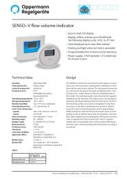
Senso differential pressure / flow<br />
volume indicator<br />
Differential pressure indicator<br />
as round mounting-unit with big LCD display.<br />
For the indication of differential pressure or filter pollution<br />
degree in %.<br />
Battery operated for at least a 3-year service life.<br />
Adjustable threshold with red LED indication<br />
in case of exceeding.<br />
Measuring ranges: 4 measuring ranges, programmable<br />
by switch-keys, see information<br />
in the related data sheet<br />
Error margin: ≤ 1.5 % of measuring range<br />
Installation dimensions: 112 x 58 mm (ø x H)<br />
2 connection nipples: ø 6 mm flush with the backside<br />
Protection class: IP 54, with add. O-ring IP 64<br />
(see accessories)<br />
Delivery incl. 2 AA batteries.<br />
SENSO accessories on page 1.18, mounting set type Senso Z<br />
1.16 | <strong>Short</strong> <strong>catalogue</strong> | Sensor ventilation air conditioning | Price <strong>list</strong> <strong>2012</strong>-3<br />
Type Item no. Euro/pc<br />
Snap fit cover<br />
adapted to built-in type<br />
square design, working range 50 <strong>–</strong> 5000 Pa Senso P5000-00 101 506 132.50<br />
round design, working range 50 <strong>–</strong> 5000 Pa Senso P5000-01 101 507 137.50<br />
Data sheet no. 13153<br />
Volume-flow indicator<br />
as round mounting-unit with big LCD display.<br />
Battery operated for at least a 3-year service life.<br />
Programming of k-factor and gas density r (Rho).<br />
Indication: m³ / h or l / sec or ft³ / min<br />
Adjustable threshold with red LED indication<br />
in case of undershooting.<br />
Measuring range: 0 <strong>–</strong> 5000 Pa<br />
Error margin: ≤ 1.5 % of measuring range:<br />
Working range: 50 <strong>–</strong> 5000 Pa<br />
Installation dimensions: 112 x 58 mm (ø x H)<br />
2 connection nipples: ø 6 mm flush with the backside<br />
Protection class: IP 54, with add. O-ring IP 64<br />
(see accessories)<br />
Delivery incl. 2 AA batteries.<br />
SENSO accessories on page 1.18, mounting set type Senso Z<br />
Snap fit cover<br />
adapted to built-in type<br />
square design Senso V5000-00 101 511 244.50<br />
round design Senso V5000-01 101 512 249.50<br />
Data sheet no. 13155
Senso differential pressure / flow<br />
volume indicator & transmitter<br />
Type Item no. Euro/pc<br />
Differential pressure indicator-transmitter-monitor<br />
as round mounting unit with big LCD display. Adjustable<br />
threshold with red LED indication in case of exceeding.<br />
Measuring range: Measuring ranges freely programmable<br />
by swtich keys in 10 Pa increments<br />
see information in the related data sheet<br />
Error margin: ≤ 1.5 % of the measuring range<br />
Installation dimensions: 112 x 58 mm (ø x H)<br />
2 connection nipples: ø 6 mm flush with the backside<br />
Supply voltage: 24 V AC / DC<br />
Output 1: 0(2) <strong>–</strong> 10 V<br />
Output 2: 0(4) <strong>–</strong> 20 mA<br />
Output 3: Relay with floating change-over<br />
Protection class: IP 54, with add. O-ring IP 64 (see accessories)<br />
SENSO accessories on page 1.18, mounting set type Senso ZP<br />
Snap fit cover, adapted to built-in type<br />
square design, working range (from S 04 on) 0 <strong>–</strong> 1000 Pa Senso PP1000-00 101 498 163.50<br />
square design, working range (from S 04 on) 10 <strong>–</strong> 5000 Pa Senso PP5000-00 101 502 182.50<br />
round design, working range (from S 04 on) 0 <strong>–</strong> 1000 Pa Senso PP1000-01 101 499 168.50<br />
round design, working range (from S 04 on) 10 <strong>–</strong> 5000 Pa<br />
Data sheet no. 13154<br />
Senso PP5000-01 101 503 187.50<br />
Low pressure-differential pressure<br />
indicator-transmitter-monitor<br />
With high precision as round mounting unit with big<br />
LCD display. Adjustable threshold with red LED indication<br />
in case of undershooting.<br />
Measuring ranges: 4 measuring ranges,<br />
programmable by switch keys<br />
Error margin: ≤ 1 % of the measuring range<br />
Technical data: like Senso PP<br />
SENSO accessories on page 1.18, mounting set type Senso ZP<br />
Snap fit cover, adapted to built-in type<br />
square design, working range ± 150 Pa Senso PP150-00 101 500 247.50<br />
round design, working range ± 150 Pa<br />
Data sheet no. 13158<br />
Senso PP150-01 101 501 252.50<br />
Volume-flow indicator-transmitter-monitor<br />
as round mounting unit with big LCD display. Adjustable<br />
threshold with red LED indication in case of undershooting.<br />
Programming of k-factor and gas density r (Rho).<br />
Indication: m³ / h or l / sec or ft³ / min<br />
Measuring range: 0 <strong>–</strong> 5000 Pa<br />
Error margin: ≤ 1.5 % of the measuring range<br />
Working range: 10 <strong>–</strong> 5000 Pa (from S 04 on)<br />
Installation<br />
dimensions: 112 x 58 mm (ø x H)<br />
2 connection<br />
nipples: ø 6 mm flush with backside<br />
Supply voltage: 24 V AC / DC<br />
Output 1: 0(2) <strong>–</strong> 10 V = ^ 0 <strong>–</strong> 99999 m³ / h<br />
Output 2: 0(4) <strong>–</strong> 20 mA = ^ 0 <strong>–</strong> 99999 m³ / h<br />
Output 3: relay with floating change-over<br />
Schutzart: IP 54, with add. O-ring IP 64 (see accessories)<br />
SENSO accessories on page 1.18, mounting set type Senso ZP<br />
Snap fit cover, adapted to built-in type<br />
square design Senso VP5000-00 101 509 284.50<br />
round design<br />
Data sheet no. 13156<br />
Senso VP5000-01 101 510 289.50<br />
www.oppermann-regelgeraete.de <strong>Short</strong> <strong>catalogue</strong> | Sensor ventilation air conditioning | Price <strong>list</strong> <strong>2012</strong>-3 | 1.17<br />
Sensors for ventilation and air conditioning
Senso-accessories<br />
1.18 | <strong>Short</strong> <strong>catalogue</strong> | Sensor ventilation air conditioning | Price <strong>list</strong> <strong>2012</strong>-3<br />
Type Item no. Euro/pc<br />
Installation cover<br />
for inner edgeless covering, to avoid filter damage.<br />
The cover is made up of pulled aluminium with<br />
3 grommets for cables and tubes on the side.<br />
Diameter ø 150 mm<br />
Height 30 mm Senso-D30 101 536 12.20<br />
Height 50 mm Senso-D50 101 537 13.50<br />
Data sheet no. 13157<br />
Mounting set<br />
consisting of bracket, stud, wingnut Senso-Z 101 556 5.50<br />
Standard for Senso P, Senso V<br />
Data sheet no. 13157<br />
Mounting set<br />
consisting of bracket, stud, wingnut Senso-ZP 101 557 7.50<br />
incl. 2 cable connections<br />
Standard for Senso PP, Senso VP<br />
Data sheet no. 13157<br />
O-ring IP 64 Senso-D 101 535 7.50<br />
to put between cover and base<br />
Data sheet no. 13157<br />
Clima-set Senso-CS 101 534 3.00<br />
consisting of: 2 connects duct and measuring unit (plastic 6551),<br />
incl. fastening screws, 2 m PVC hose ø 6 mm OD<br />
Data sheet no. 13157
Senso-accessories<br />
On-wall-mounting-housing<br />
for on-wall-mounting of the Senso-series<br />
Type Item no. Euro/pc<br />
Double L-blade<br />
Aluminium Senso KF 101 545 14.00<br />
Data sheet no. 13157<br />
L-form<br />
Aluminium Senso KW 101 546 12.00<br />
Data sheet no. 13157<br />
Self-contained housing<br />
with shortened faces on the side,<br />
for the outlet of tubes andcables if necessary<br />
Housing for 1 Senso, aluminium Senso G1-AL 101 541 on request<br />
Housing for 1 Senso, white <strong>–</strong> powder-coated RAL 9001 Senso G1-P 101 540 23.00<br />
Housing for 2 Sensos, aluminium Senso G2-AL on request on request<br />
Housing for 2 Sensos, white <strong>–</strong> powder-coated RAL 9001 Senso G2-P 101 542 27.50<br />
Housing for 3 Sensos, aluminium Senso G3-AL on request on request<br />
Housing for 3 Sensos, white <strong>–</strong> powder-coated RAL 9001 Senso G3-P 101 543 33.00<br />
Housing for 4 Sensos, aluminium Senso G4-AL on request on request<br />
Housing for 4 Sensos, white <strong>–</strong> powder-coated RAL 9001 Senso G4-P 101 544 35.00<br />
Data sheet no. 13157<br />
Sun protection device<br />
white <strong>–</strong> powder-coated RAL 9001 Senso protection 101 553 35.50<br />
Data sheet no. 13157<br />
www.oppermann-regelgeraete.de <strong>Short</strong> <strong>catalogue</strong> | Sensor ventilation air conditioning | Price <strong>list</strong> <strong>2012</strong>-3 | 1.19<br />
Sensors for ventilation and air conditioning
Sensors for air quality<br />
1.20 | <strong>Short</strong> <strong>catalogue</strong> | Sensor ventilation air conditioning | Price <strong>list</strong> <strong>2012</strong>-3<br />
Type Item no. Euro/pc<br />
CO 2 and temperature transducer<br />
Measuring range CO 2: 0 <strong>–</strong> 3000 ppm; temperature 0 <strong>–</strong> +50 °C<br />
(factory-made preset to 0 <strong>–</strong> 2000 ppm) for regulation of the<br />
demands of ventilation systems dependent on number of people.<br />
The measuring principle is based on non-dispersive infrared<br />
technology with automatic self-calibration. 5 year service intervals.<br />
Output for CO 2 and temperature: 0 <strong>–</strong> 10 V or 4 <strong>–</strong> 20 mA each,<br />
programmable. If equipped with LCD display the concentration<br />
of CO 2 and the temperature are shown alternately;<br />
serial communication interface.<br />
Voltage supply: 24 V AC / DC ± 20 %<br />
Housing for vertical interior wall fastening.<br />
Housing: 97 x 61 x 19 mm (L x W x D); white; IP 30<br />
CO 2 and temperature transducer, with display CO 2-W-D-2.5 100 092 450.00<br />
CO 2 and temperature transducer, without display CO 2-W-2.5 100 083 405.00<br />
CO 2 and temperature transducer, without display,<br />
with relay output CO 2-W-2.5-RA 102 654 450.00<br />
CO 2 and temperature transducer, with display,<br />
with relay output CO 2-W-D-2.5-RA 102 655 485.00<br />
Data sheet no. 14101<br />
CO 2 transducer<br />
Low cost specification, since there is no temperature<br />
output. Indoor installation.<br />
Measuring range CO 2: 0 <strong>–</strong> 2000 ppm<br />
For regulation of the demands of ventilation<br />
system dependent on number of people.<br />
The measuring principle is based on non-dispersive<br />
infrared technology with automatic self-calibration.<br />
2 outputs: 1x 0 <strong>–</strong> 10 V und 1x 2 <strong>–</strong> 10 V / 4 <strong>–</strong> 20 mA<br />
(FAI: only 1 x 0 <strong>–</strong> 10 V)<br />
Power supply: 24 V AC / DC ± 20 %<br />
CO 2 transducer with display CO 2-WD-LC 100 089 390.00<br />
CO 2 transducer without display CO 2-W-LC 100 093 345.00<br />
CO 2 transducer with display, LED traffic light + buzzer CO 2-WD-LC-FAI 100 090 390.00<br />
Data sheet no. 14106<br />
CO2 transducer for duct installation<br />
for installation in air ducts<br />
Measuring range CO2: 0 <strong>–</strong> 2000 ppm<br />
Measuring range temperature: 0 <strong>–</strong> 50 °C<br />
For regulation of the demands of ventilation system<br />
dependent on number of people. The measuring principle<br />
is based on non-dispersive infrared technology with<br />
automatic self-calibration.<br />
2 outputs: 0 <strong>–</strong> 10 V and 2 <strong>–</strong> 10 V / 4 <strong>–</strong> 20 mA<br />
Power supply: 24 V AC / DC ± 20 %<br />
Protection class: IP 65<br />
Housing material: ABS, flameproof according to UL 94 (JEC 707)<br />
Dimensions: 84 x 142 x 46 mm (L x W x D),<br />
outlet tube 245 mm<br />
CO2 transducer with display CO2-K-DLC 100 067 491.00<br />
CO2 transducer without display CO2-K-LC 100 068 444.00<br />
CO2 and temperature transducer, with display CO2-K-D 100 078 542.00<br />
CO2 and temperature transducer, without display<br />
Data sheet no. 14106 / 14101<br />
CO2-K 100 075 495.00
Sensors for air quality<br />
Type Item no. Euro/pc<br />
CO 2 alarm system<br />
in accordance with the dispensing equipment regulation<br />
TRSK 400<br />
1 central unit and 1 CO 2 sensor CO 2-standard set 1 101 630 675.00<br />
1 central unit and 2 CO 2 sensors CO 2-standard set 2 101 632 1.085.00<br />
Voltage supply: 230 V AC,<br />
Measuring range: 0 <strong>–</strong> 30,000 ppm<br />
The gold-cladded measuring cell ensures accurate measurements<br />
and long life-time including a 5-year calibration guarantee.<br />
Optical and acoustic warning, 2-step, plus fan activation.<br />
Data sheet no. 14151<br />
CO2 / humidity and temperature transducers / controller<br />
for CO2 air temperature and humidity measuring in rooms<br />
Voltage supply:<br />
Measuring range:<br />
24 V AC (15 <strong>–</strong> 28 V) / 1 VA<br />
24 V DC (15 <strong>–</strong> 36 V) / 1 W<br />
temperature: 0 <strong>–</strong> +50 °C<br />
Humidity: 0 <strong>–</strong> 100 % RH<br />
CO2 : 0 <strong>–</strong> 2000 ppm<br />
Outputs: 3 x 0 <strong>–</strong>10 V (< 2 mA) linear towards measuring<br />
range output A03 can be programmed to the maximum value<br />
of all measurements or alternatively as P-controller<br />
(see data sheet HDH-C)<br />
Housing: plastic ABS<br />
Dimensions:<br />
Equipment<br />
87 x 86 x 30 mm (L x W x D)<br />
variants:<br />
Protection<br />
see table<br />
class: IP 20, color: RAL 9010<br />
Automatic self-calibration (can be switched off).<br />
Service with auto-calibration at 5 year intervals.<br />
Configuration and calibration via programmer<br />
CO2 / temperature sensor without a display screen with HDH 100 905 430.00<br />
CO2 / temperature sensor with display<br />
CO2 / humidity and temperature measuring transducer<br />
HDH-N 100 908 475.00<br />
without LCD display<br />
CO2 / humidity and temperature measuring transducer<br />
HDH-RH 102 695 615.00<br />
with LCD display HDH-RH-N 102 696 630.00<br />
Option<br />
CO 2 alarm indicator lights for HDH consisting of a cover and LED HDH-AL3 102 697 82.00<br />
Only available for equipment without a display!<br />
Green: CO < 750 ppm; yellow: CO > 750 ppm; red: CO > 1250 ppm<br />
Data sheet no. 14107<br />
Programmer HDH-C 100 907 98.00<br />
for HDH and Modbus sensor. Necessary for programming.<br />
Paper and add-on board with display and cover<br />
Data sheet no. 20507<br />
www.oppermann-regelgeraete.de <strong>Short</strong> <strong>catalogue</strong> | Sensor ventilation air conditioning | Price <strong>list</strong> <strong>2012</strong>-3 | 1.21<br />
Sensors for ventilation and air conditioning
Sensors for air quality<br />
1.22 | <strong>Short</strong> <strong>catalogue</strong> | Sensor ventilation air conditioning | Price <strong>list</strong> <strong>2012</strong>-3<br />
Type Item no. Euro/pc<br />
CO 2 / humidity and hand-held temperature measuring device CO 2-TEMP-RH-HMG 100 081 395.00<br />
for simultaneous measuring of temperature, humidity, CO 2-TEMP-HMG 100 082 298.00<br />
(RH version only) and CO 2 indoors. Large LCD display with<br />
backlight and actual value, MIN / MAX display;<br />
15 min. or 8 h average value display; dew point display.<br />
CO 2 and humidity calibration.<br />
Alarm buzzer. Internal self-diagnostic system.<br />
Power supply: 4 x AA batteries (included)<br />
Measuring range: temperature: 0 <strong>–</strong> +50 °C (accuracy +/- 0.5 °C)<br />
Humidity: 0 <strong>–</strong> 95 % RH (RH version only)<br />
(accuracy +/- 3 % at 25 °C and<br />
10 <strong>–</strong> 90 % RH, otherwise +/- 5 %)<br />
CO 2: 0 <strong>–</strong> 5000 ppm (RH version)<br />
(accuracy +/- 30 ppm<br />
and +/- 5 % of reading)<br />
0<strong>–</strong>2000 ppm (standard version)<br />
(accuracy +/- 75 ppm and<br />
+/- 5 % of reading)<br />
Output: RS 232 data interface<br />
Housing: plastic ABS / PC<br />
Dimensions: 70 x 210 x 58 mm (L x W x D)<br />
Weight: about 180 g (without batteries)<br />
Data sheet no. 14108<br />
VOC Sensor VOC-W-LC 102 335 285.00<br />
Semiconductor transmitter for indoor installation<br />
Supply voltage: 24 V DC<br />
Output signal: 0 <strong>–</strong> 10 V linear<br />
Measuring range: 450 <strong>–</strong> 2000 ppm CO2 equivalent<br />
Automatic calibration<br />
Housing for wall mounting<br />
Color: white<br />
Dimensions: 78.3 x 83.4 x 25.5 mm (L x W x D)<br />
Permissible ambient<br />
temperature: 0 <strong>–</strong> 50 °C<br />
Permissible humidity: 5 <strong>–</strong> 95 % RH non-condensing<br />
The CO 2 equivalent is determined by detection of various VOCs<br />
(Volatile Organic Compounds)<br />
such as alcohols, aldehydes, CO, CH 4, LPG, ketones,<br />
organic acids, etc.<br />
Data sheet no. 14152
Vibration monitor<br />
Type Item no. Euro/pc<br />
Electronic vibration monitor<br />
For monitoring the overall level of vibration for machines<br />
and equipment on non-rotating component surfaces<br />
according to ISO 10816.<br />
If it exceeds a set limit the switch contact falls out (NC).<br />
Additional output as current signal 4 <strong>–</strong> 20 mA.<br />
Adjustable response delay.<br />
Supply voltage: 18 <strong>–</strong> 32 V DC<br />
Connecting thread: M8<br />
Measuring range: 0 <strong>–</strong> 25 mm/s vibration rate VKV021 102 333 216.00<br />
0 <strong>–</strong> 50 mm/s vibration rate VKV022 102 334 216.00<br />
Switching contact: 500 mA loadable<br />
Response delay: 1 <strong>–</strong> 60 s<br />
Protection class: IP 67<br />
Connector for flow sensor EVC002 100 433 24.00<br />
M12, 5 m, black, straight<br />
Data sheet no. 15503<br />
www.oppermann-regelgeraete.de <strong>Short</strong> <strong>catalogue</strong> | Sensor ventilation air conditioning | Price <strong>list</strong> <strong>2012</strong>-3 | 1.23<br />
Sensors for ventilation and air conditioning
Pipe burst detector<br />
Leakage sensor<br />
1.24 | <strong>Short</strong> <strong>catalogue</strong> | Sensor ventilation air conditioning | Price <strong>list</strong> <strong>2012</strong>-3<br />
Type Item no. Euro/pc<br />
Pipe burst detector VVK 2 102 357 95.00<br />
for the monitoring of water leakage of pipes, floorings and<br />
collecting trays. In case of appearance of water a relay with<br />
change-over contact connects.<br />
Supply voltage: 24 V AC / DC<br />
Alarm points: < 80 kΩ / < 10 kΩ,<br />
adjustable by DIP-switches<br />
Contact load: 230 V, 5 A<br />
Dimensions: 35 x 79 x 114 mm (L x W x D)<br />
Data sheet no. 15102<br />
Leakage sensor VVA 2 102 356 38.00<br />
with 2 m cable to lay on the floor.<br />
Dimensions: 57 x 77 x 15 mm (L x W x D)<br />
Data sheet no. 15102<br />
Leakage sensor VVA 1 102 355 38.00<br />
Installation in collecting trays.<br />
Protection class: IP 54<br />
Data sheet no. 15102<br />
Humidity sensor band VVN on request 15.50<br />
Cotton with inserted blank copper wires and <strong>price</strong> per<br />
2 m connection cable per meter. meter<br />
Min. 2 m, max. 50 m<br />
Data sheet no. 15102
Presence detectors<br />
Type Item no. Euro/pc<br />
Presence detector 24 V AC / DC OPP-PIR-1 101 348 98.00<br />
in white housing with socket, angle of coverage 110°,<br />
covering range at height of 2.4 m: 15 m,<br />
adjustable time lag relay 0.1 <strong>–</strong> 10 min and hunting relay<br />
0.1 <strong>–</strong> 30 min, floating switch-over contact.<br />
Contact output loadable with 24 V / 3 A,<br />
Housing dimensions: 67 x 115 x 48 mm (L x W x D)<br />
Protection class: IP 20<br />
Including swivelling panel MB 99 for wall and ceiling fastening.<br />
Data sheet no. 15603<br />
Presence detector 24 V AC / DC, ceiling mounting OPP-PIR-2 101 349 113.00<br />
in white housing with socket, angle of coverage 360°,<br />
adjustable time lag and hunting relay 0.1 <strong>–</strong> 25 min,<br />
floating switch-over contact.<br />
The presence detector is a passive infrared sensor with coverage<br />
thresholds for movement and presence and was especially<br />
developed for ventilation and air conditioning technology.<br />
The maximum installation height is 4.2 m.<br />
Dimensions: ø 110 mm x 40 mm height<br />
Protection class: IP 41<br />
Data sheet no. 15601<br />
Combination presence and brightness dectector<br />
24 V AC / DC; ceiling mounting OPP-PIR-LUX-1 102 688 128.00<br />
In a white housing with base, 360° detection zone,<br />
built-in PIR sensor for motion and CdS photocell for brightness.<br />
Multi-stage adjustable delay (0 sec <strong>–</strong> 10 min)<br />
and follow-up time (10 s <strong>–</strong> 30 min)<br />
Floating contact for ventilation control (max. 30 V DC, 0.2 A max)<br />
TTL output (standby 0 V/5 V active) for lighting control<br />
Reaction speed 0.1~3.0 m/sec.<br />
Specifically designed for ventilation and air conditioning.<br />
Maximung installation height: 4.2 m<br />
(Coverage area: ø 10.5 m).<br />
Dimensions: ø 110 mm x 60 mm Höhe<br />
Supply voltage: 24 V AC / DC (+/- 2V); 8 mA standby; 20 mA aktiv<br />
Data sheet no. 15604<br />
www.oppermann-regelgeraete.de <strong>Short</strong> <strong>catalogue</strong> | Sensor ventilation air conditioning | Price <strong>list</strong> <strong>2012</strong>-3 | 1.25<br />
Sensors for ventilation and air conditioning
Light intensity sensors<br />
1.26 | <strong>Short</strong> <strong>catalogue</strong> | Sensor ventilation air conditioning | Price <strong>list</strong> <strong>2012</strong>-3<br />
Type Item no. Euro/pc<br />
Light intensity sensor (active) Lux 24 101 121 154.00<br />
Detects the light intensity by the photo diode<br />
and transforms it into a linear output signal.<br />
Housing: ABS<br />
Protection class: IP 20<br />
Colour: RAL 9010<br />
Dimensions: 85 x 85 x 32 mm (L x W x D)<br />
Measuring range: 0 <strong>–</strong> 2,000 Lux<br />
Error limit: + / -10 %<br />
Supply: 24 V AC, 1 VA<br />
Output: 0 <strong>–</strong> 10 V or 4 <strong>–</strong> 20 mA optionally (jumper)<br />
Data sheet no. 15701<br />
Light intensity and temperature sensor (active) Lux 34 101 122 154.00<br />
Detects the light intensity (by the photo diode)<br />
and the temperature by transforming them into<br />
a linear output signal.<br />
Housing: Plastic PBT / PC / PA<br />
Protection class: IP 54<br />
Dimensions: 94 x 94 x 44 mm (L x W x D)<br />
Colour: Upper part white <strong>–</strong> box dark grey<br />
Measuring ranges: 0 <strong>–</strong> 1,000 Lux or 0 <strong>–</strong> 10,000 Lux (jumper)<br />
-50 <strong>–</strong> +50 °C<br />
Supply: 24 V AC / DC, < 0.1 VA<br />
Output: 2 x 0 <strong>–</strong> 10 V DC<br />
Data sheet no. 15702<br />
Light intensity and temperature sensor (passive) Lux 11 + NTC 10 101 120 79.00<br />
Detects the light intensity (by the photo diode) Lux 11 + NTC 20 102 661 79.00<br />
and the temperature.<br />
Housing: Plastic PBT / PC / PA<br />
Protection class: IP 54<br />
Dimensions: 94 x 94 x 44 mm (L x W x D)<br />
Colour: Upper part white <strong>–</strong> box dark grey<br />
Measuring ranges /<br />
resistors: 0 <strong>–</strong> 800 Lux (30 <strong>–</strong> 3.0 kΩ)<br />
-50 <strong>–</strong> +80 °C<br />
(see characteristic line NTC 10 or NTC 20)<br />
Data sheet no. 15703
Temperature and humidity sensors<br />
Notice: for chapter 2 another scale of discount is applied!<br />
Standard temperature sensor Immersion temperature sensors<br />
TEAT TENA TEKV TEV TEKY TESK<br />
page 2.2 page 2.4 page 2.4 page 2.5 page 2.5 page 2.6<br />
Immersion sleeve Air duct flange Actual value display Surface mounted temperature sensors<br />
MF TE-N TEP TEPK<br />
page 2.3 page 2.3 page 2.3 page 2.7 page 2.7<br />
Air duct temperature sensors, average value<br />
MWP 3/6 MWP TEKA..500 TEKHA<br />
page 2.8 page 2.8 page 2.8 page 2.6<br />
Outside temperature Dew point monitor Wireless sensor<br />
sensor and sensor<br />
TEU O-EGH 1.5 TEFL.. TEUFL FLTA<br />
page 2.9 page 2.9 page 2.15 page 2.15 page 2.17<br />
Room temperature sensor<br />
TES HLS, Controller TEHR-L TEHR-P TEHR-MOD TEHR<br />
page 2.10 page 2.10 page 2.11 page 2.11 page 2.12 page 2.11<br />
Humidity-temperature sensor<br />
KLH KLU KLK OPP-HBC.. OPP-HSC..<br />
page 2.13 page 2.13 page 2.14 page 2.18 page 2.18<br />
Antifreeze monitor 2-phase antifreeze controller EX-measuring transducer EX-air duct sensor<br />
air-side water-side<br />
OPP-FRO.. OPP-FRO-S.. JVA TEK-EX OP-Exl-IMU-1<br />
page 2.19 page 2.20 page 2.20 page 2.21 page 2.21<br />
www.oppermann-regelgeraete.de <strong>Short</strong> <strong>catalogue</strong> | Temperature and humidity sensors | Price <strong>list</strong> <strong>2012</strong>-3 | 2.1<br />
Temperature and and humidity sensors
Immersion temperature sensors<br />
Table of tolerance values<br />
Sensing element Tolerance<br />
Standard temperature sensor TEAT..<br />
for the measurement of temperatures of liquid media in<br />
pipelines and containers with appropriate immersion sleeves<br />
or for the measurement of temperatures in air ducts with<br />
mounting flange.<br />
Measuring range: see table<br />
Nominal width: ø 6 mm<br />
Material: stainless steel<br />
Sensor length: see table<br />
Sensors: see table<br />
Leakage resistance: ≥ 100 MΩ, 20 °C, 500 V DC<br />
Protection class: IP 54<br />
Cable connection: M16, strain-relieved<br />
Housing material: plastic, PBT, PC, PA<br />
Colour: light grey and dark grey<br />
Data sheet no. 20100<br />
* possible measuring ranges: 0 °C <strong>–</strong> 50 °C, 0 °C <strong>–</strong> 100 °C, -50 °C <strong>–</strong> +50 °C, -50 °C <strong>–</strong> +150 °C, adjustable<br />
* active sensors are equipped with sensing element PT 100<br />
NTC 1.8 ± 0.3 °C / 0 °C<br />
235 Z / KP10 ± 0.1 °C / 0 °C<br />
NI 1000 ± 0.4 K / 0 °C<br />
NI 1000 LG ± 0.4 °C / 0 °C<br />
PTC 1000 ±1.3 °C / 25 °C<br />
PT 100 ± 0.3 °C / EN 60751 / B<br />
PT 1000 ± 0.3 °C / EN 60751 / B<br />
2.2 | <strong>Short</strong> <strong>catalogue</strong> | Temperature and humidity sensors | Price <strong>list</strong> <strong>2012</strong>-3<br />
Sensing element Tolerance<br />
Type Euro/pc.<br />
Item no.<br />
Sensing device type<br />
50 100 150<br />
Sensor length mm / (Euro/pc.)<br />
200 250 300 350 450<br />
TEAT-NTC 1.8<br />
20.10 20.10 22.00 22.00 23.20 23.20 24.10 25.30<br />
Item no.<br />
101 729 101 730 101 731 101 732 101 733 101 734 101 735 101 736<br />
TEAT-235 Z / KP10<br />
23.20 23.20 25.30 25.30 25.80 25.80 26.80 27.90<br />
Item no.<br />
101 807 101 809 101 810 101 811 101 812 101 813 101 814 101 815<br />
TEAT-NI 1000<br />
22.90 22.90 24.80 24.80 25.60 25.60 26.80 27.90<br />
Item no.<br />
101684 101686 101687 101688 101690 101691 101692 101694<br />
TEAT-NI 1000 LG<br />
22.90 22.90 24.80 24.80 25.60 25.60 26.80 27.90<br />
Item no.<br />
101 816 101818 101 819 101 820 101 821 101 822 101 823 101 824<br />
TEAT-PTC 1000<br />
29.30 29.30 31.50 31.50 32.50 32.50 33.60 34.60<br />
Item no.<br />
101 825 101 826 101 827 101 828 101 829 101 830 101 831 101 832<br />
TEAT-PT 100<br />
20.10 20.10 22.00 22.00 23.20 23.20 24.10 25.30<br />
Item no.<br />
101 751 101 753 101 755 101 756 101 757 101 758 101 760 101 761<br />
TEAT-PT 1000<br />
20.10 20.10 22.00 22.00 23.20 23.20 24.10 25.30<br />
Item no.<br />
101 763 101 766 101 770 101 773 101 776 101 779 101 782 101 786<br />
TEAT-PT 100,1/3 DIN on request<br />
TEAT-NTC 10 - AN<br />
21.70 21.70 23.50 23.50 24.80 24.80 25.60 26.80<br />
Item no.<br />
101 703 101 704 101 705 101 706 101 707 101 708 101 709 101 710<br />
TEAT-NTC 10<br />
20.10 20.10 22.00 22.00 23.20 23.20 24.10 25.30<br />
Item no.<br />
101 695 101 696 101 697 101 698 101 699 101 700 101 701 101 702<br />
TEAT-NTC 10 KB<br />
23.80 23.80 25.80 25.80 26.30 26.30 27.40 28.40<br />
Item no.<br />
101 721 101 722 101 723 101 724 101 725 101 726 101 727 101 728<br />
TEAT-NTC 20<br />
20.10 20.10 22.00 22.00 23.20 23.20 24.10 25.30<br />
Item no.<br />
101 712 101 714 101 715 101 716 101 717 101 718 101 719 101 720<br />
*TEAT-LL (4 <strong>–</strong> 20 mA)<br />
54.00 54.00 56.00 56.00 57.00 57.00 58.50 59.50<br />
Item no.<br />
101 662 101 665 101 667 101 668 101 669 101 671 101 672 101 673<br />
*TEAT-LU (0 <strong>–</strong> 10 V)<br />
54.00 54.00 56.00 56.00 57.00 57.00 58.50 59.50<br />
Item no.<br />
101 674 101 676 101 677 101 678 101 679 101 680 101 682 101 683<br />
PT 100, 1 / 3 DIN ± 0.1 °C / EN 60751 / 1 / 3 DIN<br />
PT 1000, 1 / 3 DIN ± 0.1 °C / EN 60751 / 1 / 3 DIN<br />
NTC 10 - AN ± 0.3 °C / EN 60751 / B<br />
NTC 10 ± 0.2 °C / 25 °C<br />
NTC 10 KB ± 0.5 °C / 25 °C<br />
NTC 20 ± 0.2 °C / 25 °C
Accessories<br />
Immersion sleeve type<br />
type ATM, nickel-plated brass*<br />
Item no.<br />
type AT, stainless steel 1.4301*<br />
Item no.<br />
Immersion sleeve<br />
for use with Standard temperature sensor TEAT..<br />
Nominal width: G½ A<br />
Nominal pressure: Type ATM, PN 16, nickel-plated brass<br />
Type AT, PN 16, stainless steel 1.4301<br />
Immersion depth: see table<br />
Data sheet no. 20100<br />
* plus the relevant current material <strong>price</strong> surcharge<br />
The capacity of the immersion sleeves (protective tubes) depends on the process medium, pressure, temperature, flow rate as well as<br />
the design of the protective tube and the installation situation. In critical operating conditions a separate calculation is recommended.<br />
The professional planner/implementing company is responsible for the selection of the immersion sleeve appropriate for the application.<br />
Current local rules and regulations are to be observed, in particular:<br />
• VDE/VDI 3511 Technical temperature measurements<br />
• DIN 43772 Control technology <strong>–</strong> metal protective tubes and extension tubes for liquid-in-glass thermometers, dial thermometers,<br />
thermocouples and resistance thermometers <strong>–</strong> dimensions, materials, testing<br />
• VDI Guideline 2035, Page 2 <strong>–</strong> water related corrosion; preventing damage in hot water heating systems<br />
Stainless steel tubes are to be selected for cooling devices, well water and contact with food.<br />
Ordering example: Immersion depth 100 mm,<br />
stainless steel PN 16<br />
Measuring element: NTC 20,<br />
Type TEAT-NTC 20-AT100<br />
Type Item no. Euro/pc.<br />
Immersion depth mm / (Euro / pc.)<br />
50 100 150 200 250 300 350 450<br />
6.50<br />
100 038<br />
11.20<br />
100 024<br />
7.00<br />
100 040<br />
11.70<br />
100 027<br />
7.50<br />
100 041<br />
12.20<br />
100 029<br />
8.20<br />
100 042<br />
12.70<br />
100 031<br />
8.50<br />
100 043<br />
13.40<br />
100 033<br />
9.00<br />
100 044<br />
13.90<br />
100 035<br />
9.50<br />
100 045<br />
14.50<br />
100 036<br />
10.60<br />
100 046<br />
15.00<br />
100 037<br />
Air duct flange<br />
for use with Standard temperature sensor TEAT..<br />
Installation: for straight and round air ducts with lip MF..<br />
for airproof termination,<br />
2 holes to screw on the air duct<br />
Hole diameter: 13 mm with screw for fastening of the MF 13 101 190 2.60<br />
Standard temperature sensor, standard<br />
Hole diameter: 6 mm, therefore relocatable over the MF 6 101 192 2.60<br />
whole sensor length<br />
Data sheet no. 20100<br />
Actual value display TE-N 102 171 36.00<br />
fits to all round connecting heads of sensors with<br />
active outputs of type ..LL or ..LU.<br />
The cover is plugged onto the electronic board via ribbon<br />
cable and the connector is protected against polarity reversal.<br />
The device is ready for operation without any adjustment<br />
Data sheet no. 20100<br />
Transducer<br />
converts the passive sensor signal PT 100 to 0 <strong>–</strong> 10 V or<br />
4 <strong>–</strong> 20 mA-signals. Housing with snap fit cover of PBT,<br />
with or without display<br />
Dimensions: 115 x 115 x 45 mm (L x W x D)<br />
Protection class: IP 54<br />
Strain-relieved cable connection M16<br />
Output 4 <strong>–</strong> 20 mA, without display LLK 101 110 45.00<br />
Output 4 <strong>–</strong> 20 mA, with display LLK-N 101 111 87.00<br />
Output 0 <strong>–</strong> 10 V, without display LUK 101 118 45.00<br />
Output 0 <strong>–</strong> 10 V, with display LUK-N 101 119 87.00<br />
Data sheet no. 20700<br />
www.oppermann-regelgeraete.de <strong>Short</strong> <strong>catalogue</strong> | Temperature and humidity sensors | Price <strong>list</strong> <strong>2012</strong>-3| 2.3<br />
Temperature and humidity sensors
Immersion temperature sensors<br />
2.4 | <strong>Short</strong> <strong>catalogue</strong> | Temperature and humidity sensors | Price <strong>list</strong> <strong>2012</strong>-3<br />
Type Item no. Euro/pc.<br />
Immersion temperature sensor<br />
for the measurement of liquid media in pipelines.<br />
Immersion sleeve included.<br />
Measuring range: -50 <strong>–</strong> +120 °C, see table<br />
Nominal width: G½ A ø 4 x 100 mm, stainless steel 1.4404<br />
Nominal pressure: PN 16<br />
Sensors: see table<br />
Leakage resistance: ≥ 100 MΩ, 20 °C, 500 V DC<br />
Protection class: IP 54<br />
Cable connection: M16<br />
Housing material: Plastic, PBT, PC, PA<br />
Colour: light grey and dark grey<br />
NTC 1.8 k Ω / 25 °C, tolerance ± 0.3 °C / 0 °C, TENA NTC 1,8 102 085 39.50<br />
NI 1000 Ω / 0 °C, tolerance ± 0.4 K / 0 °C, DIN TENA-NI 1000 102 082 38.50<br />
1000 Ω / 25 °C, tolerance ± 1.3 °C / 25 °C, TENA PTC 1000 102 090 70.50<br />
100 Ω / 0 °C, tolerance ± 0.3 °C / 0 °C, EN 60751/B TENA PT 100 102 087 37.50<br />
1000 Ω / 0 °C, tolerance ± 0.3 °C / 0 °C, (Honeywell, Danfoss) TENA PT 1000 102 089 37.50<br />
10 kΩ / 25 °C, tolerance ± 0.2 °C / 25 °C, (Andover) TENA NTC 10-AN 102 662 70.50<br />
10 kΩ / 25 °C, tolerance ± 0.2 °C / 25 °C, (Trend) TENA NTC 10 102 084 37.50<br />
5.025 kΩ / 25 °C, tolerance ± 0.5 °C / 25 °C, (Satchwell) TENA NTC 10-KB 102 663 53.00<br />
20 kΩ / 25 °C, tolerance ± 0.2 °C / 25 °C, (Honeywell) TENA NTC 20 102 086 37.50<br />
1000 Ω / 0 °C, tolerance ± 0.4 K / 0 °C, (Siemens) TENA NI 1000-LG 102 083 39.50<br />
2-wire supply voltage 15 <strong>–</strong> 35 V DC, output 4 <strong>–</strong> 20 mA *TENA LL ... 102 079 64.00<br />
3-wire supply voltage 24 V AC / DC, output 0 <strong>–</strong> 10 V < 2 mA* TENA LU ... 102 081 64.00<br />
*possible measuring ranges:<br />
0 °C <strong>–</strong> 50 °C, 0 °C <strong>–</strong> 100 °C, -50 °C <strong>–</strong> +50 °C, -50 °C <strong>–</strong> +150 °C,<br />
adjustable<br />
Data sheet no. 20102<br />
Immersion temperature sensor for heating and cooling<br />
for the measurement of temperature in liquid media<br />
and gaseous media. Immersion depth adjustable by<br />
Ermeto-screw connection.<br />
Measuring range: -50 <strong>–</strong> +120 °C, see table<br />
Nominal width: G¼ A ø 4 x 200 mm, stainless steel 1.4404<br />
Nominal pressure: PN 16<br />
Sensors: see table<br />
Leakage resistance: ≥ 100 MΩ, 20 °C, 500 V DC<br />
Protection class: IP 54<br />
Cable connection: M16<br />
Housing material: plastic, PBT, PC, PA<br />
Colour: light grey and dark grey<br />
NTC 1.8 k kΩ / 25 °C, tolerance ± 0.3 °C / 0 °C TEKV NTC 1,8 102 664 37.00<br />
NI 1000 Ω / 0 °C, tolerance ± 0.4 K / 0 °C, DIN TEKV-NI 1000 102 026 34.50<br />
100 Ω / 0 °C, tolerance ± 0.3 °C / 0 °C, EN 60751/B TEKV PT 100 102 031 34.50<br />
1000 Ω / 0 °C, tolerance ± 0.3 °C / 0 °C, (Honeywell, Danfoss) TEKV PT 1000 102 032 34.50<br />
10 kΩ / 25 °C, tolerance ± 0.2 °C / 25 °C, (Andover) TEKV NTC 10-AN 102 029 34.50<br />
10 kΩ / 25 °C, tolerance ± 0.2 °C / 25 °C, (Trend) TEKV NTC 10 102 028 34.50<br />
20 kΩ / 25 °C, tolerance ± 0.2 °C / 25 °C, (Honeywell) TEKV NTC 20 102 030 34.50<br />
1000 Ω / 0 °C, tolerance ± 0.4 K / 0 °C, (Siemens) TEKV NI 1000-LG 102 027 34.50<br />
2-wire supply voltage 15 <strong>–</strong> 35 V DC, output 4 <strong>–</strong> 20 mA *TEKV LL .. 102 022 62.00<br />
3-wire supply voltage 24 V AC / DC, output 0 <strong>–</strong> 10 V < 2 mA *TEKV LU .. 102 024 62.00<br />
*possible measuring ranges:<br />
0 °C <strong>–</strong> 50 °C, 0 °C <strong>–</strong> 100 °C, -50 °C <strong>–</strong> +50 °C, -50 °C <strong>–</strong> +150 °C,<br />
adjustable<br />
Data sheet no. 20103
Immersion temperature sensors<br />
Type Item no. Euro/pc.<br />
Immersion temperature sensor with cable connection<br />
for the measurement of temperature in liquid media and<br />
gaseous media.<br />
Immersion depth adjustable by Ermeto-screw connection.<br />
Measuring range: -50 <strong>–</strong> +120 °C see table<br />
Nominal width: G¼ A ø 4 x 200 mm, stainless steel 1.4305<br />
Nominal pressure: PN 16<br />
Sensors: see table<br />
Leakage resistance: ≥ 100 MΩ, 20 °C, 500 V DC<br />
Cable connection: 2 m LIYY 2 x 0.14<br />
NTC 1.8 kΩ / 25 °C, tolerance ± 0.3 °C / 0 °C, TEV NTC 1,8 102 665 47.50<br />
NI 1000 Ω / 0 °C, tolerance ± 0.4 K / 0 °C, DIN TEV-NI 1000 102 161 28.50<br />
*100 Ω / 0 °C, tolerance ± 0.3 °C / 0 °C, EN 60751/B TEV PT 100 102 166 28.50<br />
1000 Ω / 0 °C, tolerance ± 0.3 °C / 0 °C, (Honeywell, Danfoss) TEV PT 1000 102 168 28.50<br />
10 kΩ / 25 °C, tolerance ± 0.2 °C / 25 °C, (Andover) TEV NTC 10-AN 102 666 47.50<br />
10 kΩ / 25 °C, tolerance ± 0.2 °C / 25 °C, (Trend) TEV NTC 10 102 163 28.50<br />
5.025 kΩ / 25 °C, tolerance ± 0.5 °C / 25 °C, (Satchwell) TEV NTC 10-KB 102 164 64.00<br />
20 kΩ / 25 °C, tolerance ± 0.2 °C / 25 °C, (Honeywell) TEV NTC 20 102 165 28.50<br />
1000 Ω / 0 °C, tolerance ± 0.4 K / 0 °C, (Siemens) TEV NI 1000-LG 102 162 28.50<br />
*active output in separate housing (see page 2.3 LLK, LUK)<br />
Data sheet no. 20104<br />
Cable temperature sensor<br />
for the measurement of temperature in containers.<br />
Measuring range: -50 <strong>–</strong> +70 °C, optional up to 100 °C<br />
Cable connection: 2 m LIYY 2 x 0.14<br />
Sensor size: ø 6 mm<br />
Sensors: see table<br />
Leakage resistance: ≥ 100 MΩ, 20 °C, 500 V DC<br />
NTC 1.8 kΩ / 25 °C, tolerance ± 0.3 °C / 0 °C, TEKY NTC 1,8 102 052 15.50<br />
NI 1000 Ω / 0 °C, tolerance ± 0.v4 K / 0 °C, DIN TEKY-NI 1000 102 040 15.50<br />
*100 Ω / 0 °C, tolerance ± 0.3 °C / 0 °C, EN 60751/B TEKY PT 100 102 057 15.50<br />
1000 Ω / 0 °C, tolerance ± 0.3 °C / 0 °C, (Honeywell, Danfoss) TEKY PT 1000 102 061 15.50<br />
10 kΩ / 25 °C, tolerance ± 0.2 °C / 25 °C, (Andover) TEKY NTC 10-AN 102 050 15.50<br />
10 kΩ / 25 °C, tolerance ± 0.2 °C / 25 °C, (Trend) TEKY NTC 10 102 049 15.50<br />
5.025 kΩ / 25 °C, tolerance ± 0.5 °C / 25 °C, (Satchwell) TEKY NTC 10-KB 102 056 35.00<br />
20 kΩ / 25 °C, tolerance ± 0.2 °C / 25 °C, (Honeywell) TEKY NTC 20 102 054 15.50<br />
1000 Ω / 0 °C, tolerance ± 0.4 K / 0 °C, (Siemens) TEKY NI 1000-LG 102 044 15.50<br />
Additional charge more than 2 m per m 1.00<br />
*active output in separate housing (see page 2.3 LLK, LUK)<br />
Data sheet no. 20105<br />
www.oppermann-regelgeraete.de <strong>Short</strong> <strong>catalogue</strong> | Temperature and humidity sensors | Price <strong>list</strong> <strong>2012</strong>-3| 2.5<br />
Temperature and humidity sensors
Immersion temperature sensors<br />
2.6 | <strong>Short</strong> <strong>catalogue</strong> | Temperature and humidity sensors | Price <strong>list</strong> <strong>2012</strong>-3<br />
Type Item no. Euro/pc.<br />
Air duct temperature sensor<br />
for measuring temperature in air ducts.<br />
The sensor TEKHA is designed for the measurement of<br />
temperature in combination with automated ventilation systems.<br />
Including mounting flange.<br />
Measuring range: -50 <strong>–</strong> +70 °C<br />
Cable connection: LIYY 2 x 0.14: length 2 m<br />
Sensor size: ø 6 x 100 mm, stainless steel<br />
Duct connection: plastic flange<br />
Sensors: see table<br />
Nominal resistance: 1000 Ω / 0 °C<br />
NTC 1.8 kΩ / 25 °C, tolerance ± 0.3 °C / 0 °C, TEKHA NTC 1,8 102 018 16.50<br />
NI 1000 Ω / 0 °C, tolerance ± 0.4 K / 0 °C, DIN TEKHA-NI 1000 102 015 16.50<br />
100 Ω / 0 °C, tolerance ± 0.3 °C / 0 °C, EN 60751/B TEKHA PT 100 102 020 16.50<br />
1000 Ω / 0 °C, tolerance ± 0.3 °C / 0 °C, (Honeywell, Danfoss) TEKHA PT 1000 102 021 16.50<br />
10 kΩ / 25 °C, tolerance ± 0.2 °C / 25 °C, (Andover) TEKHA NTC 10-AN 102 667 33.00<br />
10 kΩ / 25 °C, tolerance ± 0.2 °C / 25 °C, (Trend) TEKHA NTC 10 102 017 16.50<br />
20 kΩ / 25 °C, tolerance ± 0.2 °C / 25 °C, (Honeywell) TEKHA NTC 20 102 668 16.50<br />
1000 Ω / 0 °C, tolerance ± 0.4 K / 0 °C, (Siemens) TEKHA NI 1000-LG 102 016 16.50<br />
Data sheet no. 20107<br />
Immersion temperature sensor<br />
for the measurement of temperature of liquid media in pipelines.<br />
Immersion depth adjustable by Ermeto-screw connection.<br />
Measuring range: 0 <strong>–</strong> 400 °C<br />
Nominal width: G½ A, ø 10 x 100 .. 200 mm,<br />
Edelstahl 1.4404<br />
Nominal pressure: PN 16<br />
Sensors: see table<br />
Leakage resistance: ≥ 100 MΩ, 20 °C, 500 V DC<br />
Protection class: IP 54<br />
Cable connection: M16<br />
Housing material: aluminium<br />
100 Ω / 0 °C, tolerance ± 0.3 °C/ 0 °C, EN 60751/B TESK PT 100 102 131 132.00<br />
1000 Ω / 0 °C, tolerance ± 0.3 °C/ 0 °C, (Honeywell, Danfoss) TESK PT 1000 102 132 132.00<br />
2-wire supply voltage 15 <strong>–</strong> 35 V DC, output 4 <strong>–</strong> 20 mA TESK LL 0/400 102 129 179.00<br />
3-wire supply voltage 24 V AC / DC, output 0 <strong>–</strong> 10 V < 2 mA TESK LU 0/400 102 130 179.00<br />
Data sheet no. 20106
Surface mounted temperature sensors<br />
Type Item no. Euro/pc.<br />
Surface mounted temperature sensor<br />
for the measurement of temperatures on the surfaces of<br />
pipelines. Tensioning belt and heat-conductive paste included.<br />
Measuring range: see table Nominal width: ø 32 <strong>–</strong> 80 mm<br />
Time constant: 2 s Sensors: see table<br />
Protection class: IP 54 Cable connection: M16<br />
Leakage resistance: ≥ 100 MΩ, 20 °C, 500 V DC<br />
Housing material: plastic, PBT, PC, PA<br />
Colour: light grey and dark grey<br />
NTC 1.8 kΩ / 25 °C, tolerance ± 0.3 °C / 0 °C, TEP NTC 1,8 102 098 29.00<br />
LM 235Z 2732 mV / 0 °C, tolerance ± 0.1 °C / 0 °C TEP 235 Z 102 107 34.00<br />
NI 1000 Ω / 0 °C, tolerance ± 0.4 K / 0 °C, DIN TEP-NI 1000 102 093 29.00<br />
100 Ω / 0 °C, tolerance ± 0.3 °C / 0 °C, EN 60751/B TEP PT 100 102 100 29.00<br />
1000 Ω / 0 °C, tolerance ± 0.3 °C / 0 °C, (Honeywell, Danfoss) TEP PT 1000 102 103 29.00<br />
10 kΩ / 25 °C, tolerance ± 0.2 °C / 25 °C, (Andover) TEP NTC 10-AN 102 096 33.00<br />
10 kΩ / 25 °C, tolerance ± 0.2 °C / 25 °C, (Trend) TEP NTC 10 102 095 29.00<br />
5.025 kΩ / 25 °C, tolerance ± 0.5 °C / 25 °C, (Satchwell) TEP NTC 10-KB 102 097 33.00<br />
20 kΩ / 25 °C, tolerance ± 0.2 °C / 25 °C, (Honeywell) TEP NTC 20 102 099 29.00<br />
1000 Ω / 0 °C, tolerance ± 0.4 K / 0 °C, (Siemens) TEP NI 1000-LG 102 094 29.00<br />
2-wire supply voltage 15 <strong>–</strong> 35 V DC, output 4 <strong>–</strong> 20 mA *TEP LL .. 102 091 65.00<br />
3-wire supply voltage 24 V AC / DC, output 0 <strong>–</strong> 10 V < 2 mA *TEP LU .. 102 092 65.00<br />
*possible measuring ranges:<br />
0 °C <strong>–</strong> 50 °C, 0 °C <strong>–</strong> 100 °C, -50 °C <strong>–</strong> +50 °C, -50 °C <strong>–</strong> +150 °C,<br />
adjustable<br />
Data sheet no. 20200<br />
Surface mounted temperature sensor with cable<br />
for the measurement of temperature on plane areas and pipes.<br />
For low add-on height<br />
Measuring range: see table<br />
Sensitivity: < 55 °C<br />
Sensor size: 41 x 16 x 6 mm (L x W x D)<br />
Sensor housing: zinc<br />
Sensor fastening: with band at pipes,<br />
screwed on plain surfaces<br />
Sensors: see table<br />
Cable connection: 2 m LIYY 2 x 0.14<br />
NTC 1.8 kΩ / 25 °C, tolerance ± 0.3 °C / 0 °C, TEPK NTC 1,8 102 112 16.50<br />
NI 1000 Ω / 0 °C, tolerance ± 0.4 K / 0 °C, DIN TEPK-NI 1000 102 108 16.50<br />
*100 Ω / 0 °C, tolerance ± 0.3 °C / 0 °C, EN 60751/B TEPK PT 100 102 115 15.50<br />
1000 Ω / 0 °C, tolerance ± 0.3 °C / 0 °C, (Honeywell, Danfoss) TEPK PT 1000 102 116 15.50<br />
10 kΩ / 25 °C, tolerance ± 0.2 °C / 25 °C, (Andover) TEPK NTC 10 AN 102 111 33.00<br />
10 kΩ / 25 °C, tolerance ± 0.2 °C / 25 °C, (Trend) TEPK NTC 10 102 110 15.50<br />
5.025 kΩ / 25 °C, tolerance ± 0.5 °C / 25 °C, (Satchwell) TEPK NTC 10 KB 102 114 43.50<br />
20 kΩ / 25 °C, tolerance ± 0.2 °C / 25 °C, (Honeywell) TEPK NTC 20 102 113 15.50<br />
1000 Ω / 0 °C, tolerance ± 0.4 K / 0 °C, (Siemens) TEPK NI 1000-LG 102 109 16.50<br />
*active output in separate housing<br />
(see page 2.3 LLK, LUK)<br />
Data sheet no. 20201<br />
www.oppermann-regelgeraete.de <strong>Short</strong> <strong>catalogue</strong> | Temperature and humidity sensors | Price <strong>list</strong> <strong>2012</strong>-3| 2.7<br />
Temperature and humidity sensors
Air duct temperature sensors, average value<br />
2.8 | <strong>Short</strong> <strong>catalogue</strong> | Temperature and humidity sensors | Price <strong>list</strong> <strong>2012</strong>-3<br />
Type Item no. Euro/pc.<br />
Air duct temperature sensor, average value<br />
for the measurement of average temperatures in air ducts.<br />
Fully flexible active sensor rod.<br />
Measuring range: -50 <strong>–</strong> +50 °C<br />
Protection class: IP 54<br />
NI 1000 LG sensor length 3000 mm MWP3 NI1000-LG 101 232 107.00<br />
NI 1000 LG sensor length 6000 mm MWP6 NI1000-LG 101 237 127.00<br />
NI 1000 sensor length 3000 mm MWP3 NI1000 101 231 107.00<br />
NI 1000 sensor length 6000 mm MWP6 NI1000 101 249 127.00<br />
PT 1000 sensor length 3000 mm MWP3 PT1000 101 234 107.00<br />
PT 1000 sensor length 6000 mm MWP6 PT1000 101 239 127.00<br />
LU 1000 sensor length 3000 mm MWP3 LU 101 228 159.00<br />
LU 1000 sensor length 6000 mm MWP6 LU 101 230 188.00<br />
LL 1000 sensor length 3000 mm MWP3 LL 101 227 159.00<br />
LL 1000 sensor length 6000 mm MWP6 LL 101 229 188.00<br />
Data sheet no. 20302<br />
Air duct temperature sensor, average value<br />
For the measurement of temperature in air ducts with patented<br />
fitting flange and flexible, fully active sensor rod.<br />
Measuring range: -50 <strong>–</strong> +50 °C<br />
Sensor length: 400 mm, ø 6 mm<br />
Cable connection: M16<br />
Protection class: IP 54<br />
NI 1000 Ω / 0 °C, tolerance ± 0.5 °C / 0 °C, DIN MWP-400 NI 1000 101 242 79.00<br />
1000 Ω / 0 °C, tolerance ± 0.5 °C / 0 °C, (Siemens) MWP-400 NI 1000-LG 101 244 79.00<br />
100 Ω / 0 °C, tolerance ± 0.3 °C / 0 °C, EN 60751/B MWP-400 PT 100 101 247 79.00<br />
PT 1000 Ω / 0 °C, tolerance ± 0.3 °C / 0 °C, (Honeywell, Danfoss) MWP-400 PT 1000 101 248 79.00<br />
4 <strong>–</strong> 20 mA, tolerance ± 0.3 °C / 0 °C MWA-400 LL 102 674 140.00<br />
4 <strong>–</strong> 10, tolerance ± 0.3 °C / 0 °C MWA-400 LU 101 223 140.00<br />
Data sheet no. 20302<br />
Air duct temperature sensor, average value<br />
for the measurement of air flows in air ducts,<br />
sensor rod, including mounting flange<br />
Measuring range: -50 <strong>–</strong> +70 °C<br />
Bar sensor: stainless steel, ø 8 x 500 mm,<br />
4 sensing devices<br />
Flexible sensor rod: 500 mm, 4 sensing devices<br />
Cable connection: M16<br />
Housing material: plastic PBT/PC/PA, IP 54<br />
Colour: light grey and dark grey<br />
NTC 1.8 kΩ / 25 °C, tolerance ± 0.3 °C / 0 °C, TEKA-NTC 1,8 101 995 99.00<br />
NI 1000 Ω / 0 °C, tolerance ± 0.4 K / 0 °C, DIN TEKA-NI 1000 101 991 99.00<br />
1000 Ω / 0 °C, tolerance ± 0.4 K / 0 °C, (Siemens) TEKA-NI 1000-LG 101 985 99.00<br />
100 Ω / 0 °C, tolerance ± 0.3 °C / 0 °C, EN 60751/B TEKA-PT 100 102 012 99.00<br />
1000 Ω / 0 °C, tolerance ± 0.3 °C / 0 °C, (Honeywell, Danfoss) TEKA-PT 1000 102 003 99.00<br />
10 kΩ / 25 °C, tolerance ± 0.2 °C / 25 °C, (Andover), TEKA-NTC 10-AN 102 672 142.00<br />
10 kΩ / 25 °C, tolerance ± 0.2 °C / 25 °C, (Trend) TEKA-NTC 10 101 994 99.00<br />
5.025 kΩ / 25 °C, tolerance ± 0.5 °C / 25 °C, (Satchwell) TEKA-NTC 10 KB 102 673 99.00<br />
20 kΩ / 25 °C, tolerance ± 0.2 °C / 25 °C, (Honeywell) TEKA-NTC 20 101 998 99.00<br />
4 <strong>–</strong> 20 mA, tolerance ± 0.3 °C / 0 °C, *TEKA-LL (4 <strong>–</strong> 20 mA) 101 975 134.00<br />
4 <strong>–</strong> 10, tolerance ± 0.3 °C / 0 °C, *TEKA-LU (0 <strong>–</strong> 10 V) 101 979 134.00<br />
*possible measuring ranges: (adjustable)<br />
0 °C <strong>–</strong> 50 °C, 0 °C <strong>–</strong> 100 °C, -50 °C <strong>–</strong> +50 °C, -50 °C <strong>–</strong> +150 °C,<br />
Data sheet no. 20302
Outside temperature sensors<br />
Type Item no. Euro/pc.<br />
Outside temperature sensors<br />
for the measurement of the outside temperature<br />
or the temperature in humid areas,<br />
e.g. cold stores or greenhouses<br />
Measuring range: -50 <strong>–</strong> +120 °C, see table<br />
Housing: ø 70 x 47 mm<br />
Sensors: see table<br />
Leakage resistance: ≥ 100 MΩ, 20 °C, 500 V DC<br />
Protection class: IP 54<br />
Housing material: plastic, PBT, PC, PA<br />
Colour: light grey and dark grey<br />
NTC 1.8 kΩ / 25 °C, tolerance ± 0.3 °C / 0 °C, TEU NTC 1,8 102 142 12.50<br />
LM 235Z 2732 mV/ 0 °C, tolerance ± 0.1 °C / 0 °C, TEU 235 Z 102 158 16.50<br />
NI 1000 Ω / 0 °C, tolerance ± 0.4 K / 0 °C, DIN TEU-NI 1000 102 137 14.50<br />
*100 Ω / 0 °C, tolerance ± 0.3 °C / 0 °C, EN 60751/B TEU PT 100 102 144 12.50<br />
1000 Ω / 0 °C, tolerance ± 0.3 °C / 0 °C, (Honeywell, Danfoss) TEU PT 1000 102 150 12.50<br />
10 kΩ / 25 °C, tolerance ± 0.2 °C / 25 °C, (Andover) TEU NTC 10-AN 102 140 14.50<br />
10 kΩ / 25 °C, tolerance ± 0.2 °C / 25 °C, (Trend) TEU NTC 10 102 139 12.50<br />
5.025 kΩ / 25 °C, tolerance ± 0.5 °C / 25 °C, (Satchwell) TEU NTC 10-KB 102 141 33.50<br />
20 kΩ / 25 °C, tolerance ± 0.2 °C / 25 °C, (Honeywell) TEU NTC 20 102 143 12.50<br />
1000 Ω / 0 °C, tolerance ± 0.4 K / 0 °C, (Siemens) TEU NI 1000-LG 102 138 14.50<br />
2-wire supply voltage 15 <strong>–</strong> 35 V DC, output 4 <strong>–</strong> 20 mA *TEU LL .. 102 134 78.50<br />
3-wire supply voltage 24 V AC / DC, output 0 <strong>–</strong> 10 V < 2 mA *TEU LU .. 102 136 78.50<br />
*active output in housing KLU<br />
Data sheet no. 20400<br />
Dew point monitor and sensor<br />
Dew point monitor and sensor 24 V AC / DC O-EGH 1.5 101 317 109.00<br />
for the protection of cooling chamber ceilings<br />
against condesation, contact and analogue output,<br />
silicone-free design,<br />
springy supported dew point sensor that connects a relay with<br />
change-over contact at approx. 85 % RH (max. 1 A 24 V AC / DC)<br />
An additional analogue signal 0 <strong>–</strong> 10 V is available for the range<br />
of 70 <strong>–</strong> 85 % RH<br />
Delivery includes tensioning belt for pipes up to ø 10 <strong>–</strong> 100 mm<br />
and heat-conductive paste.<br />
Dimensions: 60 x 60 x 33 mm (L x W x D)<br />
Protection class: IP 40<br />
Data sheet no. 15503<br />
www.oppermann-regelgeraete.de <strong>Short</strong> <strong>catalogue</strong> | Temperature and humidity sensors | Price <strong>list</strong> <strong>2012</strong>-3| 2.9<br />
Temperature and humidity sensors
Room temperature sensors<br />
2.10 | <strong>Short</strong> <strong>catalogue</strong> | Temperature and humidity sensors | Price <strong>list</strong> <strong>2012</strong>-3<br />
Type Item no. Euro/pc.<br />
Temperature sensor for damp locations<br />
to record the temperature in special rooms, industry,<br />
greenhouses, saunas, cold storage rooms etc.<br />
Measuring range: see table<br />
Housing: aluminium, dimensions: 80 x 60 x 40 mm<br />
Sensors: see table<br />
Protection class: IP 67<br />
Colour: dark grey<br />
NTC 1.8 kΩ / 25 °C, tolerance ± 0.3 °C / 0 °C, TES NTC 1,8 102 675 58.00<br />
LM 235Z 2732 mV/ 0 °C, tolerance ± 0.1 °C / 0 °C, TES 235 Z 102 128 59.00<br />
NI 1000 Ω / 0 °C, tolerance ± 0.4 K / 0 °C, DIN TES-NI 1000 102 122 58.00<br />
100 Ω / 0 °C, tolerance ± 0.3 °C / 0 °C, EN 60751/B TES PT 100 102 126 58.00<br />
1000 Ω / 0 °C, tolerance ± 0.3 °C / 0 °C, (Honeywell, Danfoss) TES PT 1000 102 127 58.00<br />
10 kΩ / 25 °C, tolerance ± 0.2 °C / 25 °C, (Andover) TES NTC 10-AN 102 676 60.00<br />
10 kΩ / 25 °C, tolerance ± 0.2 °C / 25 °C, (Trend) TES NTC 10 102 124 58.00<br />
5.025 kΩ / 25 °C, tolerance ± 0.5 °C / 25 °C, (Satchwell) TES NTC 10-KB 102 677 65.00<br />
20 kΩ / 25 °C, tolerance ± 0.2 °C / 25 °C, (Honeywell) TES NTC 20 102 125 58.00<br />
1000 Ω / 0 °C, tolerance ± 0.4 K / 0 °C, (Siemens) TES NI 1000-LG 102 123 58.00<br />
active output in separate housing (see page 2.3 LLK, LUK).<br />
Data sheet no. 20650<br />
Temperature sequence controller<br />
for room temperature with internal sensor HLS 33 100 914 58.00<br />
for room temperature with internal sensor and display HLS 33 N 100 916 90.00<br />
for controllers with external sensor HLS 33 Ext 100 915 58.00<br />
for controllers with external sensor and display HLS 33 N Ext 100 917 90.00<br />
Room temperature controller for 2 thermic drives HLS 21 100 912 46.00<br />
Room temperature controller for 2 thermic drives & display HLS 21 N 100 913 78.00<br />
Heating-cooling with outputs 0 <strong>–</strong> 10 V, 3 point,<br />
2 point for thermic drive, adjustable by jumpers<br />
Measuring range: -10 <strong>–</strong> +50 °C<br />
Housing: ABS with socket<br />
Dimensions: 85 x 85 x 28 mm (L x W x D)<br />
Colour: RAL 9010<br />
Accuracy: ± 0.5 °C / 0 °C<br />
Supply voltage: 24 V AC, 2 VA<br />
Dead band: 0 <strong>–</strong> 3 °C<br />
P-Band: 1 <strong>–</strong> 8 °C<br />
Data sheet no. 20504<br />
Room temperature controller HLS 34 100 918 105.00<br />
with display, operated by 4 keys and day/night mode*.<br />
For the control of individual room temperatures and area<br />
control. Configurable by the configuration tool HLS34-SER.<br />
*Day/night mode only switchable via Modbus<br />
Housing: ABS, IP 20, dimensions: 87 x 86 x 32 mm<br />
Colour: RAL 9010<br />
Set temperature range during the day: 21 °C +/- 3 °C<br />
Set temperature range during the night: 5 <strong>–</strong> 20 °C<br />
Accuracy: +/- 0.5 °C<br />
Supply voltage: 24 V AC / DC, < 1 VA<br />
Input: NTC10 sensor; RS485 Modbus;<br />
0 <strong>–</strong> 10 V analogue entry<br />
Output: 0 <strong>–</strong> 10 V, 2 mA and<br />
(only with AC supply) optionally 3 points<br />
switch thermal switch (24 V AC, 1 A)<br />
Data sheet no. 20505
Room temperature sensors<br />
Type Item no. Euro/pc.<br />
Room temperature sensor, active<br />
for the measurement of air temperature in rooms<br />
Measuring range: 0 <strong>–</strong> 50 °C<br />
Housing: ABS with socket; IP 20; RAL 9010<br />
Dimensions: 85 x 85 x 28 mm (L x W x D)<br />
Sensor: PT 1000, EN60751/B<br />
Accuracy: ± 0.5 °C / 0 °C<br />
2-wire supply voltage 15 <strong>–</strong> 35 V DC, output 4 <strong>–</strong> 20 mA TEHR LL 0/50 101 855 45.50<br />
2-wire supply voltage 15 <strong>–</strong> 35 V DC, output 4 <strong>–</strong> 20 mA, with display TEHR LL 0/50-N 101 856 73.50<br />
3-wire supply voltage 24 V AC / DC, output 0 <strong>–</strong> 10 V TEHR LU 0/50 101 858 45.50<br />
3-wire supply voltage 24 V AC / DC, output 0 <strong>–</strong> 10 V, with display TEHR LU 0/50-N 101 859 73.50<br />
*2-wire supply voltage 15 <strong>–</strong> 35 V DC, output 4 <strong>–</strong> 20 mA, TEHR LL 0/50-N-P 101 857 85.00<br />
*3-wire supply voltage 24 V AC / DC, output 0 <strong>–</strong> 10 V, TEHR LU 0/50-N-P 101 860 85.00<br />
*with potentiometer and display<br />
Data sheet no. 20501<br />
Room temperature sensor with set point potentiometer<br />
for the measurement of air temperature in rooms<br />
Measuring range: 0 <strong>–</strong> 50 °C<br />
Housing: ABS with socket; IP 20, RAL 9010<br />
Dimensions: 85 x 85 x 28 mm (L x W x D)<br />
Sensors:<br />
NTC 1.8 kΩ / 25 °C, tolerance ± 0.3 °C / 0 °C, TEHR NTC 1,8-P 101 892 23.00<br />
LM 235Z 2732 mV/ 0 °C, tolerance ± 0.1 °C / 0 °C, TEHR 235 Z-P 101 932 27.00<br />
NI 1000 Ω / 0 °C, tolerance ± 0.4 K / 0 °C, DIN TEHR-NI 1000-P 101 872 25.00<br />
100 Ω / 0 °C, tolerance ± 0.3 °C / 0 °C, EN 60751/B TEHR PT 100-P 101 915 23.00<br />
1000 Ω / 0 °C, tolerance ± 0.3 °C / 0 °C, (Honeywell, Danfoss) TEHR PT 1000-P 101 907 23.00<br />
10 kΩ / 25 °C, tolerance ± 0.2 °C / 25 °C, (Andover) TEHR NTC 10-AN-P 101 884 25.00<br />
10 kΩ / 25 °C, tolerance ± 0.2 °C / 25 °C, (Trend) TEHR NTC 10-P 101 888 23.00<br />
20 kΩ / 25 °C, tolerance ± 0.2 °C / 25 °C, (Honeywell) TEHR NTC 20-P 101 897 23.00<br />
1000 Ω / 0 °C, tolerance ± 0.4 K / 0 °C, (Siemens) TEHR NI 1000-LG-P 101 881 25.00<br />
Data sheet no. 20502<br />
Room temperature sensor<br />
for the measurement of air temperature in rooms<br />
Measuring range: 0 <strong>–</strong> 50 °C<br />
Housing: ABS with socket; IP 20; RAL 9010<br />
Dimensions: 85 x 85 x 28 mm (L x W x D)<br />
Sensors:<br />
NTC 1.8 kΩ / 25 °C, tolerance ± 0.3 °C / 0 °C TEHR NTC 1,8 101 891 13.50<br />
LM 235Z 2732 mV / 0 °C, tolerance ± 0.1 °C / 0 °C TEHR 235 Z 101 929 16.50<br />
NI 1000 Ω / 0 °C, tolerance ± 0.4 K / 0 °C, DIN TEHR-NI 1000 101 863 15.50<br />
100 Ω / 0 °C, tolerance ± 0.3 °C / 0 °C, EN 60751/B TEHR PT 100 101 899 14.50<br />
1000 Ω / 0 °C, tolerance ± 0.3 °C / 0 °C, (Honeywell, Danfoss) TEHR PT 1000 101 905 14.50<br />
10 kΩ / 25 °C, tolerance ± 0.2 °C / 25 °C, (Andover) TEHR NTC 10-AN 101 883 14.50<br />
10 kΩ / 25 °C, tolerance ± 0.2 °C / 25 °C, (Trend) TEHR NTC 10 101 882 14.50<br />
5.025 kΩ / 25 °C, tolerance ± 0.5 °C / 25 °C, (Satchwell) TEHR NTC 10-KB 101 887 31.00<br />
20 kΩ / 25 °C, tolerance ± 0.2 °C / 25 °C, (Honeywell) TEHR NTC 20 101 894 14.50<br />
1000 Ω / 0 °C, tolerance ± 0.4 K / 0 °C, (Siemens) TEHR NI 1000-LG 101 871 15.50<br />
Data sheet no. 20500<br />
Options for all TEHR types<br />
On / off push-button 24 V AC / DC (additional charge) TEHR-S on request 10.30<br />
5 stage switch (1, 2, 3, 0, AUTO) 24 V AC / DC (additional charge) TEHR-S5 on request 13.00<br />
TEHR-L on request 9.60<br />
www.oppermann-regelgeraete.de <strong>Short</strong> <strong>catalogue</strong> | Temperature and humidity sensors | Price <strong>list</strong> <strong>2012</strong>-3| 2.11<br />
Temperature and humidity sensors
Room temperature sensors<br />
2.12 | <strong>Short</strong> <strong>catalogue</strong> | Temperature and humidity sensors | Price <strong>list</strong> <strong>2012</strong>-3<br />
Type Item no. Euro/pc.<br />
Room temperature sensor <strong>–</strong> Modbus<br />
for measuring air temperature in rooms.<br />
Programming via HDH-C Modbus programmer.<br />
Supply voltage: 24 V AC (15 <strong>–</strong> 28 V)<br />
24 V DC (15 <strong>–</strong> 36 V)<br />
Measuring range: 0 <strong>–</strong> 50 °C<br />
Output: analogue 0 <strong>–</strong> 10 V (< 2 mA)<br />
Modbus RTU<br />
also configurable as a<br />
proportional controller 0 <strong>–</strong> 10 V)<br />
Accuracy: ± 0.5 °C (at 25 °C)<br />
Permissible humidity: 0 <strong>–</strong> 95 % RH (non-condensing)<br />
Housing: ABS<br />
Protection class: IP 20<br />
Dimensions: 87 x 86 x 30 mm (L x W x D)<br />
without display TEHR-MOD 101 936 78.00<br />
with display TEHR-N-MOD 102 678 108.00<br />
Data sheet no. 20506<br />
Modbus programmer HDH-C 100 907 98.00<br />
for all Modbus sensors. Required for programming.<br />
Add-on board with display and cover<br />
Data sheet no. 20507
Humidity temperature sensors<br />
Type Item no. Euro/pc.<br />
Room humidity and temperature sensor<br />
for measuring of the humidity and temperature in rooms<br />
Supply voltage: 24 V AC / DC < 1 VA<br />
Measuring range: Humidity: 0 <strong>–</strong> 100 % RH<br />
Temperature: 0 <strong>–</strong> 50 °C<br />
Output 1 Humidity: 0 <strong>–</strong> 10 V (0 <strong>–</strong> 100 % RH) linear<br />
Output 2 Temperature: 0 <strong>–</strong> 10 V (0 <strong>–</strong> 50 °C) linear<br />
Protection class: IP 20<br />
Housing: ABS, 87 x 86 x 30 mm (L x W x D)<br />
Colour: RAL 9010<br />
Room humidity temp. sensor KLH 100 100 999 111.00<br />
Room humidity temp. sensor with display (alternating readout) KLH 100-N 101 009 142.00<br />
Optional: Output 2 for all passive elements on request<br />
Data sheet no. 20651<br />
Room humidity and temperature sensor <strong>–</strong> Modbus<br />
for measuring relative humidity and temperature in rooms<br />
Supply voltage: 24 V AC/DC < 1 VA<br />
Measuring range: Humidity: 0 <strong>–</strong> 100 % RH<br />
Temperature: 0 <strong>–</strong> 50 °C<br />
Programming via HDH-C Modbus programmer.<br />
Output: 0 <strong>–</strong> 10 V (< 2 mA)<br />
for temperature and humidity Modbus RTU<br />
(also configurable as a proportional controller<br />
0 <strong>–</strong> 10 V either for humidity or temperature)<br />
Accuracy: ± 0.5 °C (at 25 °C)<br />
± 2 % RH (from 0 <strong>–</strong> 90 % RH)<br />
Permissible humidity: 0 <strong>–</strong> 100 % RH (non-condensing)<br />
Protection class: IP 20<br />
Housing: ABS, 87 x 86 x 30 mm (L x W x D)<br />
Colour: RAL 9010<br />
without display KLH-M 101 013 118.00<br />
with display KLH-M-N 101 014 148.00<br />
Data sheet no. 20651<br />
Modbus programmer HDH-C 100 907 98.00<br />
for all Modbus sensors. Required for programming.<br />
Add-on board with display and cover<br />
Data sheet no. 20651<br />
Outdoor humidity temperature sensor, active<br />
for the measurement of the outdoor humidity and temperature<br />
Supply voltage: 24 V AC / DC < 1 VA<br />
Measuring range: Humidity: 0 <strong>–</strong> 100 % RH<br />
Temperature: -50 <strong>–</strong> +50 °C<br />
Output 1 Humidity: 0 <strong>–</strong> 10 V (0 <strong>–</strong> 100 % RH) linear<br />
4 <strong>–</strong> 20 mA (-50 <strong>–</strong> +50 °C)<br />
Output 2 Temperature: 0 <strong>–</strong> 10 V (-50 <strong>–</strong> +50 °C)<br />
4 <strong>–</strong> 20 mA (0 <strong>–</strong> 50 % RH) linear<br />
Protection class: IP 54<br />
Housing: ABS, 85 x 85 x 40 mm (L x W x D)<br />
Outdoor humidity temp. sensor KLU 100 101 028 175.00<br />
Outdoor humidity temp. sensor with display (alternating readout) KLU 100-N 101 029 206.00<br />
Data sheet no. 20640<br />
www.oppermann-regelgeraete.de <strong>Short</strong> <strong>catalogue</strong> | Temperature and humidity sensors | Price <strong>list</strong> <strong>2012</strong>-3| 2.13<br />
Temperature and humidity sensors
Humidity temperature sensors<br />
2.14 | <strong>Short</strong> <strong>catalogue</strong> | Temperature and humidity sensors | Price <strong>list</strong> <strong>2012</strong>-3<br />
Type Item no. Euro/pc.<br />
Duct humidity and temperature sensor<br />
for the measurement of relative humidity and temperature<br />
in ventilation ducts.<br />
Supply voltage: 24 V AC / DC < 1 VA<br />
Measuring range Humidity: 0 <strong>–</strong> 100 % RH<br />
Temperature: -50 <strong>–</strong> +50 °C<br />
Output 1 Humidity: 0 <strong>–</strong> 10 V (0 <strong>–</strong> 100 % RH) linear<br />
4 <strong>–</strong> 20 mA (0 <strong>–</strong> 100 % RH) linear<br />
Output 2 Temperature: 0 <strong>–</strong> 10 V (-50 <strong>–</strong> +50 °C) linear<br />
4 <strong>–</strong> 20 mA (-50 <strong>–</strong> +50 °C) linear<br />
Protection class: IP 54<br />
Submersion:<br />
rod length: < 150 mm<br />
Housing: plastic<br />
Colour: light grey and dark grey<br />
Duct humidity and temp. sensor KLK 100 101 015 152.00<br />
Duct humidity and temp. sensor with display (alternating readout) KLK 100-N 101 024 182.00<br />
Data sheet no. 20630
Wireless sensors<br />
Type Item no. Euro/pc.<br />
Wireless humidity and temperature sensor<br />
for air temperature and humidity measurement in rooms.<br />
Power supply: 3 V 6 AA lithium battery 2 A (included)<br />
Measuring range: Temperature: 0 <strong>–</strong> +50 °C<br />
Humidity: 0 <strong>–</strong> 100 % RH<br />
(non-condensing)<br />
Housing: plastic ABS<br />
85 x 85 x 28 mm (L x W x D), IP 20<br />
Equipment varities: see table<br />
Protection class: IP 20 H<br />
Colour: RAL 9010<br />
Transmission frequency: 868.30 MHz<br />
Note: the sensors can only be used with the FLTA<br />
base station and FLAN antenna. Configuration via FLSER.<br />
Area 0 <strong>–</strong> 50 °C TEFL 101 843 98.50<br />
+ Set point 17.5 <strong>–</strong> 24.5 °C TEFL-P 101 844 109.00<br />
0 <strong>–</strong> 50 °C + relative humidity TEFL-RH 101 845 138.00<br />
0 <strong>–</strong> 50 °C + relative humidity and set point 17.5 <strong>–</strong> 24.5 °C TEFL-RH-P 101 846 149.00<br />
Display unit FL-N 100 466 38.00<br />
Required accessory for TEFL see page 2.17<br />
Data sheet no. 20803<br />
Wireless temperature sensor<br />
for outside air temperature measurement.<br />
Power supply: 3 V 6 AA lithium battery 2 Ah (included)<br />
Measuring range: Temperature: -50 <strong>–</strong> +150 °C<br />
Power: 0 <strong>–</strong> 10 V<br />
Housing: PC Plastic (Polycarbonat)<br />
85 x 85 x 40 mm (L x W x D)<br />
Protection class: IP 54<br />
Colour: light grey and dark grey<br />
Transmission frequency: 868.30 MHz<br />
Remote temperature sensor TEUFL 102 159 149.00<br />
Required accessory for TEFL see page 2.17<br />
Data sheet no. 20801<br />
Wireless humidity and temperature sensor<br />
for outside air temperature and humidity measurement.<br />
Power supply: 3 V 6 AA lithium battery 2 Ah (included)<br />
Measuring range: Temperature: -50 <strong>–</strong> +150 °C<br />
Humidity: 0 <strong>–</strong> 100 % RH<br />
(continual): 5 <strong>–</strong> 95 % RFH<br />
Lighting strength: 0 <strong>–</strong> 1000 Lux<br />
Housing: PC Plastic (Polycarbonat)<br />
85 x 85 x 40 mm (L x W x D)<br />
Protection class: IP 54<br />
Colour: light grey and dark grey<br />
Transmission frequency: 868.30 MHz<br />
Wireless humidity and temperature sensor KLUFL 101 030 191.00<br />
Required accessory for TEFL see page 2.17<br />
Data sheet no. 20802<br />
www.oppermann-regelgeraete.de <strong>Short</strong> <strong>catalogue</strong> | Temperature and humidity sensors | Price <strong>list</strong> <strong>2012</strong>-3| 2.15<br />
Temperature and humidity sensors
Wireless sensors<br />
2.16 | <strong>Short</strong> <strong>catalogue</strong> | Temperature and humidity sensors | Price <strong>list</strong> <strong>2012</strong>-3<br />
Type Item no. Euro/pc.<br />
Wireless CO 2 / humidity and temperature sensor<br />
for measuring CO 2 , air temperature and humidity in rooms<br />
Supply voltage: 24 V AC (15 <strong>–</strong> 28 V)<br />
24 V DC (15 <strong>–</strong> 36 V)<br />
Measuring range: Temperature: 0 <strong>–</strong> +50 °C<br />
Humidity: 0 <strong>–</strong> 100 % RH<br />
CO 2: 0 <strong>–</strong> 2000 ppm<br />
Outputs: 1 <strong>–</strong> 10 V linear analogue output according<br />
to the measuring range or wirelessly<br />
Housing: Plastic ABS<br />
Dimensions: 87 x 86 x 30 mm (L x W x D)<br />
Equipment variants: see table<br />
Protection class: IP 20, Colour: RAL 9010<br />
Transmission frequency: 868.30 MHz<br />
Note: the sensors can only be used with the FLTA base<br />
station and FLAN antenna. Configuration via FLSER.<br />
CO 2 / temperature sensor without display HDHFL 102 681 350.00<br />
CO 2 / temperature sensor with display HDHFL-N 102 680 380.00<br />
CO 2 / humidity/temperature sensor without display HDHFL-RH 102 679 450.00<br />
CO 2 / humidity/temperature sensor with display HDHFL-RH-N 100 906 480.00<br />
Required accessory see page 2.17<br />
Data sheet no. 20804<br />
Wireless presence and light intensity sensor<br />
Supply voltage: 3 V 6 AA lithium batteries 2 A (included)<br />
Area monitored: 140 °, 1.9 <strong>–</strong> 12 m adjustable/swivelling<br />
Light intensity<br />
measuring range: 0 <strong>–</strong> 2.000 Lux<br />
Housing: Plastic ABS, including ball coupling fixture<br />
Dimensions: 64 x 98 x 70 mm (L x W x D)<br />
Protection class: IP 40, colour: RAL 9010<br />
Transmission frequency: 868.30 MHz<br />
Note: the sensors can only be used with the FLTA base<br />
station and FLAN antenna. Configuration via FLSER.<br />
Presence sensor LAFL 102 682 165.00<br />
Presence and light intensity sensor LAFL-LX 102 684 184.00<br />
Required accessory see page 2.17<br />
Data sheet no. 20805<br />
Wireless I/O function module for combining with FLTA<br />
base station/wireless sensors/repeaters<br />
Delivery includes FLAN antenna.<br />
2 inputs and outputs can be configured.<br />
Inputs: Inputs: 2 x optionally 0 <strong>–</strong> 10 V DC<br />
or floating contact<br />
Outputs: 2 x 10A relay contact 250 V AC,<br />
2 x analogue output 0 <strong>–</strong> 10 V DC or<br />
2 x Triac PWM 24 V AC, 1 A, 20 s<br />
4 x Aux. (terminals 3, 6, 7, 9) 24 V AC
Wireless sensor accessories<br />
Type Item no. Euro/pc.<br />
Required!<br />
Base station for all wireless sensors<br />
Delivery includes (FLAN) antenna<br />
Power supply: 24 V AC / DC<br />
Transmission range: up to 500 m line of sight<br />
20 <strong>–</strong> 100 m in building<br />
Transmission frequency: 868.30 MHz<br />
Transmission strength: +8 dBm<br />
Reception sensitivity: -109 dBm<br />
Modulation type: Frequency modulation<br />
Outputs, 8 pieces: Temperature 0 <strong>–</strong> 50 °C / 0... 10 V<br />
Humidity 0 <strong>–</strong> 100 % / 0 <strong>–</strong> 10 V<br />
Set point 18 <strong>–</strong> 24 C / 0 <strong>–</strong> 10 V<br />
5-stage switch 1 <strong>–</strong> 5 V<br />
(e.g. Position 3 = 3 V)<br />
Communication interface: Modbus RTU (RS485)<br />
Housing, protection class: plastic ABS, IP 20<br />
Dimensions: 55 x 90 x 60 mm (L x W x D)<br />
Base station for all wireless sensors with (FLAN) antenna FLTA 100 465 199.00<br />
Data sheet no. 20800<br />
Antenna for base station (replacement part) FLAN 100 458 39.00<br />
Data sheet no. 20800<br />
Optional!<br />
Wireless repeater<br />
for wireless sensors in difficult surroundings<br />
(rooms and buildings). Up to 8 pieces operable via FLTA.<br />
Power supply: 12 <strong>–</strong> 24 V DC or 24 V AC<br />
Transmission frequency: 868.30 MHz<br />
Modulation type: frequency modulation<br />
Housing, protection class: plastic ABS, IP 20<br />
Dimensions: 86 x 86 x 32 mm (L x W x D)<br />
Colour: RAL 9010<br />
Wireless repeater FLREP 100 462 109.00<br />
Wireless repeater with antenna FLREP-U 100 463 160.00<br />
Data sheet no. 20850<br />
Monitoring tool FLSNIF 102 687 499.00<br />
for all wireless sensors and repeaters. Supply voltage via<br />
USB cable (included in scope of delivery).<br />
Communication for the wireless sensors / base station and<br />
repeater can be controlled with the monitoring tool.<br />
Data sheet no. 20841<br />
Configuration tool<br />
necessary for programming of all wireless sensors and repeaters<br />
Power supply: 3 V 6 AA lithium battery 2 Ah (included)<br />
Housing,<br />
Protection class: Plastic ABS, IP 20<br />
Colour: RAL 9010<br />
Configuration tool FLSER 100 464 175.00<br />
Data sheet no. 20840<br />
www.oppermann-regelgeraete.de <strong>Short</strong> <strong>catalogue</strong> | Temperature and humidity sensors | Price <strong>list</strong> <strong>2012</strong>-3| 2.17<br />
Temperature and humidity sensors
7<br />
Humidistats<br />
1<br />
%rF<br />
%R H<br />
60<br />
2<br />
10<br />
0<br />
6<br />
5<br />
8<br />
IP5 5<br />
E N60529<br />
5<br />
2.18 | <strong>Short</strong> <strong>catalogue</strong> | Temperature and humidity sensors | Price <strong>list</strong> <strong>2012</strong>-3<br />
Type Item no. Euro/pc.<br />
Duct humidistat<br />
for the monitoring and control of the relative humidity in<br />
air ducts or rooms. Readoutpotentiometer outside/inside with<br />
optional housing cover.<br />
Measuring range: 15 <strong>–</strong> 95 % RH<br />
Max. air speed: 10 m/s<br />
Contact load: max. 5 A, 230 V<br />
mind. 10 mA at 24 V<br />
Dimensions: 140 x 73 x 64 mm (L x W x D)<br />
Adjustable from: 130 <strong>–</strong> 156 mm<br />
Scope of delivery: channel humidistat with mounting<br />
flange and PG screw connection<br />
2-point-EPU OPP-HBC 1.1 101 303 179.00<br />
3-point-EPU OPP-HBC 1.2 101 304 225.00<br />
Data sheet no. 20631<br />
Housing cover<br />
with clear cover for higher protection class IP 55. GD 1.1 100 512 39.00<br />
Data sheet no. 20631<br />
Room humidistat<br />
for the monitoring and control of the relative humidity in rooms.<br />
Readoutpotentiometer outside or optionally inside.<br />
Measuring range: 30 <strong>–</strong> 90 % RH<br />
Dimensions: 76 x 76 x 34 mm (L x W x D incl. socket)<br />
Colour: RAL 9010<br />
Adjustment outside OPP-HSC 1.01 101 305 58.00<br />
Adjustment inside OPP-HSC 1.10 101 306 63.00<br />
Data sheet no. 20632<br />
Intermediate plate<br />
white, for installation on flush-mounting socket OPP-ZP 1.1 101 310 7.50<br />
Data sheet no. 20632
Antifreeze monitors<br />
Type 6551<br />
Typ 6551<br />
6,5<br />
18,5<br />
60<br />
Type Item no. Euro/pc.<br />
Antifreeze monitor<br />
to prevent freezing of air heaters. Capillaries filled with<br />
steam with accurate switching mechanism.<br />
Setting range: -18 <strong>–</strong> +13 °C<br />
Protection class with cover plate: IP 44<br />
Electric change-over contact: 16 A, 250 V<br />
Cable connection: M16 strain-relieved<br />
Delivery includes mounting plate and capillary feedthrough<br />
Capillary pipe length 3 m without reset with 4 mounting clamps OPP-FRO 3 101 287 49.50<br />
Capillary pipe length 6 m without reset with 6 mounting clamps OPP-FRO 6 101 291 53.00<br />
Data sheet no. 20671<br />
Cover plate, sealing possible AP 101 295 4.70<br />
Data sheet no. 20671<br />
Mounting plate MP 101 307 1.20<br />
Data sheet no. 20671<br />
Mounting angle OPP-MW 101 308 1.60<br />
Data sheet no. 20671<br />
Screws, sealing possible SR 101 309 2.80<br />
for antifreeze monitors<br />
6 pieces per bag<br />
Data sheet no. 20671<br />
Mounting clamp (replacement part, 1 Pc.) MK 101 196 0.85<br />
for antifreeze and average value sensors<br />
Data sheet no. 20671<br />
Duct connection nipple, plastic 6551 102 628 0.50<br />
Data sheet no. 13101<br />
www.oppermann-regelgeraete.de <strong>Short</strong> <strong>catalogue</strong> | Temperature and humidity sensors | Price <strong>list</strong> <strong>2012</strong>-3| 2.19<br />
Temperature and humidity sensors
Antifreeze controller<br />
2.20 | <strong>Short</strong> <strong>catalogue</strong> | Temperature and humidity sensors | Price <strong>list</strong> <strong>2012</strong>-3<br />
Type Item no. Euro/pc.<br />
2-phase antifreeze control, downstream<br />
for the monitoring of antifreeze air heaters, downstream.<br />
Capillary tube made of copper with accurate shifter mechanism<br />
to prevent freezing and with analogue output 0 <strong>–</strong> 10 V for<br />
proportional opening of control valves.<br />
Set-point potentiometer, operating mode switch, reset<br />
push-button and LED, accessible behind a transparent<br />
screw-off type cover.<br />
Direct installation on ventilation devices.<br />
Dimensions: 96 x 137 x 67 mm (L x W x D)<br />
Supply voltage: 24 V AC<br />
Measuring range: 0 <strong>–</strong> 15 °C<br />
Proportional range: 2 K<br />
Output 1: 0 <strong>–</strong> 10 V<br />
Output 2: Relay with change-over contact<br />
max. 230 V, 6 A<br />
min. 5 V, 5 mA<br />
Protection class: IP 42<br />
Scope of delivery: with PG screw connection M16,<br />
grommet, screws, mounting clamps<br />
Capillary tube length 2 m, with 4 mounting clamps OPP-FRO-S2 101 297 189.00<br />
Capillary tube length 6 m, with 6 mounting clamps OPP-FRO-S6 101 298 224.00<br />
Data sheet no. 20672<br />
Mounting clamps (replacement part 1 pc.) MK 101 196 0.50<br />
for antifreeze and average value sensors<br />
Data sheet no. 20672<br />
2-phase antifreeze control, water-side<br />
for the proportional opening of control valves via the 0 <strong>–</strong> 10 V<br />
output signal and the shutdown of fans and pumps.<br />
For installation in control cabinets. Temperature sensors PT 1000<br />
or NI 1000 LG, can be connected. With reset button, LED for<br />
antifreeze and LED for prewarning that flashes if the output<br />
signal for the valve drive is being raised. 2 relay outputs for<br />
the input to the automation station and for the shutdown<br />
of pumps and fans.<br />
Dimensions: 90 x 53 x 60 mm (L x W x D)<br />
for DIN installation rail<br />
Supply voltage: 24 V AC / DC, 2 VA<br />
Measuring range: 0 <strong>–</strong> 16 °C<br />
Proportional range: 2 °C fixed<br />
2-phase antifreeze control JVA 24 100 966 101.20<br />
2-phase antifreeze control with the possibility to keep JVS 24 100 967 105.20<br />
a constant temperature in case of switched-off fans,<br />
e.g. on roof devices or start-up circuits / set point 0 <strong>–</strong> 50 °C<br />
Data sheet no. 20670
EX measuring transformers<br />
Type Item no. Euro/pc.<br />
EX air duct temperature sensor TEK EX 101 950 81.00<br />
with ATEX approval<br />
in combination with EX measuring transformer zone 1+2<br />
Measuring range: -50 <strong>–</strong> +120 °C<br />
Nominal width: 6 mm<br />
Material: stainless steel<br />
Sensor length: 200 mm<br />
Sensor: NI 1000 LG<br />
Protection class: IP 54<br />
Cable connection: M16, strain-relieved<br />
Housing material: plastic PBT, PC, PA<br />
Colour: light grey and dark grey<br />
Data sheet no. 20681<br />
EX universal measuring transformer OP-ExL-IMU-1 101 311 610.00<br />
for passive sensors in EX areas<br />
of the zones 0, 1, 2, 20, 21, 22.<br />
PTB certified according to ATEX No.: PTB03ATEX2092.<br />
Inherently safe electrical circuit for the transfer of passive<br />
signals from the Ex area to the safe area.<br />
The sensor signals are transferred to (0) 4 <strong>–</strong> 20 mA.<br />
The calibration of the sensors with different characteristics<br />
takes place in the unit. Includes a big illuminated LCD display<br />
that is used both for calibration, error messages and indication<br />
of the actual value.<br />
Supply voltage: 24 V AC / DC ±20 %<br />
Attachable sensors: Pt 100 DIN, KP 10, Pt 500,<br />
Pt 1000 DIN, NI 1000 LG, LF 20,<br />
resistance transmitter 0 <strong>–</strong> 1 kΩ und NI 500<br />
Data sheet no. 20680<br />
www.oppermann-regelgeraete.de <strong>Short</strong> <strong>catalogue</strong> | Temperature and humidity sensors | Price <strong>list</strong> <strong>2012</strong>-3| 2.21<br />
Temperature and humidity sensors
Resistance values<br />
Temp. NI 1000 DIN PTC 1000 PT 100 PT 1000 NTC 10-AN NTC 10 NTC-KB NTC 20 NI 1000LG NTC 1.8 LM235Z<br />
°C Ω Ω Ω Ω kΩ kΩ Ω kΩ Ω kΩ mV<br />
-50 743 518 80.31 803.10 441.30 672.600 9854 1659.082 790.88 63.229 2232<br />
-40 791 570 84.27 842.70 239.80 337.270 9712 810.861 830.83 35.480 2332<br />
-30 842 625 88.22 882.20 135.20 176.680 9466 414.698 871.69 20.660 2432<br />
-20 893 685 92.16 921.60 78.91 96.970 9067 221.088 913.48 12.440 2532<br />
-10 946 748 96.04 960.90 47.54 55.300 8472 122.431 956.24 7.730 2632<br />
±0 1000 815 100.00 1000.00 29.49 32.660 7661 70.203 1000.00 4.940 2732<br />
+10 1056 886 103.90 1039.00 18.79 19.900 6667 41.567 1044.79 3.240 2832<br />
+20 1112 961 107.79 1077.90 12.26 12.490 5573 25.350 1090.65 2.170 2932<br />
+25 1141 1000 109.74 1097.40 10.00 10.000 5025 20.000 1113.99 1.800 2982<br />
+30 1171 1040 111.67 1116.70 8.19 8.055 4492 15.887 1137.61 1.490 3032<br />
+40 1230 1123 115.54 1155.40 5.59 5.320 3518 10.211 1185.71 1.050 3132<br />
+50 1291 1209 119.40 1194.00 3.89 3.600 2702 6.718 1234.97 0.750 3232<br />
+60 1353 1300 123.24 1332.40 2.76 2.490 2056 4.517 1285.44 0.550 3332<br />
+70 1417 1394 127.07 1270.70 1.99 1.750 1563 3.099 1337.14 0.402 3432<br />
+80 1483 1492 130.89 1308.90 1.46 1.260 1193 2.166 1390.12 0.300 3532<br />
+90 1549 1594 134.70 1347.00 1.08 0.920 923 1.541 1444.39 0.230 3632<br />
+100 1618 1700 138.50 1385.00 0.82 0.680 723 1.114 1500.00 0.180 3732<br />
+110 1688 1812 142.29 1422.90 0.62 0.510 576 0.820 1556.98 0.140 3832<br />
+120 1760 1923 146.06 1460.60 0.48 0.390 467 0.609 1615.36 0.110 3932<br />
+130 1833 2041 149.82 1498.20 0.38 0.300 385 0.460 1675.18 0.090 4032<br />
+140 1909 2128 153.58 1535.80 0.30 0.230 324 0.350 1736.47 0.071 4132<br />
+150 1987 157.33 1573.30 0.24 0.180 0.270 1799.26 4232<br />
Notice: The self warming by the measuring current affects the measuring precision and<br />
may not exceed a maximum of 10 mA.<br />
Target values: PT 100, PT 1000 (thin film) < 2 mA<br />
NI 1000 DIN < 2 mA<br />
NTC S < 1 mA<br />
To avoid inductive interspersion the sensor wire must be run shielded (J-Y(St) 2 x 2 x 0.8).<br />
Sensor wires must not be run parallel to conductors.<br />
Please take notice of the EMV guidelines!<br />
Chart of tolerance values Table of tolerance values [ ±°C]<br />
Tolerance ± °C<br />
Temperature ± °C<br />
2.22 | <strong>Short</strong> <strong>catalogue</strong> | Temperature and humidity sensors | Price <strong>list</strong> <strong>2012</strong>-3<br />
Temperature °C -200 -100 0 100 200<br />
Class A 0.55 0.35 0.15 0.35 0.55<br />
Class B 1.3 0.8 0.3 0.8 1.3<br />
1/3 DIN 0.44 0.27 0.1 0.27 0.44<br />
1/5 DIN 0.26 0.16 0.06 0.16 0.26<br />
1/10 DIN 0.13 0.08 0.03 0.08 0.13
Gas and CO warning devices<br />
Sensor<br />
GMF 4.E.CO.08 MOD<br />
GMF 4.E.NO2.03 MOD<br />
GMF 4.P.C3H8.30.MOD<br />
BR 2.6<br />
Sensor-DUO<br />
GMF-DUO.E/<br />
P.CO/LPG-MOD<br />
BR 2.6<br />
Gas warning devices are for monitoring rooms for toxic and<br />
flammable gases. For example, the max. permissible working<br />
place concentrations, the so-called MAK-value, or the lower<br />
explosive limit (UEG) of gases and vapour is monitored. When<br />
the adjusted threshold value is exceeded, optical and acoustic<br />
alarm devices are turned on. This way people are warned in<br />
time and can leave the endangered area. Via additional floating<br />
contacts e.g. solenoid valves, the corresponding media lines can<br />
be closed.<br />
Therefore gas warning devices provide optimum protection<br />
for persons and technical systems from the negative effects<br />
of gases and vapour.<br />
by<br />
STOP THE ENGINE <strong>–</strong> LEAVE THE GARAGE<br />
STOP THE ENGINE <strong>–</strong> LEAVE THE GARAGE<br />
Slave 3<br />
BS 2.6 BS 2.6<br />
ZONE 4<br />
In particular CO warning devices are used together with<br />
ventilation systems are used to avoid excessive and harmful<br />
concentrations of carbon monoxide in underground car<br />
parks and tunnels.<br />
For this purpose CO sensors that measure and analyse the<br />
CO contents of the inhaled air at 1.5 m height are installed in<br />
the car park. The CO sensors have to be installed at a height<br />
of 1.5 <strong>–</strong> 1.8 m.<br />
The CO monitoring system is TÜV-certified and is suitable for<br />
use in all German federal states in accordance with the current<br />
regulations for car parks; also in Switzerland, Austria and the<br />
Netherlands. To save cable material the sensors are connected<br />
via a proprietary bus.<br />
NO2 sensors are used for the survey of diesel emissions.<br />
Please observe all local regulations and rules. Make sure<br />
that products are completely suitable for your application.<br />
www.oppermann-regelgeraete.de <strong>Short</strong> <strong>catalogue</strong> | Gas and CO warning devices | Price <strong>list</strong> <strong>2012</strong>-3 | 3.1<br />
Gas and CO warning devices
CO warning devices for underground<br />
car parks and tunnels<br />
System description for TGÜ-BM2.6<br />
The TGÜ-BM 2.6 is a bus-compliant measuring and control<br />
system for monitoring CO-NO 2-LPG concentration of inhaled<br />
air in underground car parks or similar closed buildings, where<br />
there are cars and vehicles with running combustion engines.<br />
Different types of gas sensors can be connected simultaneously.<br />
50 CO/NO 2 or 12 DUO sensors can be connected directly.<br />
A repeater can be interconnected to the Modbusline, if more<br />
sensors are needed. This increases the number of possible<br />
sensors to 100 CO/NO 2 or 40 DUO.<br />
The control center has one integrated alarm zone. If more alarm<br />
zones are needed (up to 4), an additional zone device (TGÜ BS2.6)<br />
is required for every zone. Every zone device is connected via bus<br />
with the control center. The zone device has no control elements.<br />
The setting-up and the control of the whole unit occurs through<br />
the control center. The interfaces to ventilators, transparent<br />
warning lights and horns as well as to the sensors are designed<br />
the same as in the control center. With every zone device an<br />
extension of the number of sensors is possible via the repeater<br />
(TGÜ-BR 2.6). The connection between control center and<br />
sensor occurs via 4-wire-system: 2 for supply and 2 for data<br />
communication.<br />
The communication between the control center and the gas<br />
sensors is carried out digitally by bus. The control center cyclically<br />
requests the current values from the gas sensors and stores the<br />
results for further processing. In the same way bus and sensors<br />
are also monitored. Malfunctions will be signalised.<br />
3.2 | <strong>Short</strong> <strong>catalogue</strong> | Gas and CO warning devices | Price <strong>list</strong> <strong>2012</strong>-3<br />
Type Item no. Euro/pc.<br />
The gas sensors signals in the sensor electronics are digitalized.<br />
Measured data will be temperature compensated, scaled and<br />
analysed according to the adjusted average time. In case the<br />
preset threshold control commands are exceeded, this is passed<br />
on via relay or optocoupler for ventilators, transparent warning<br />
lights, horns, Gerätestörmeldung (GSM) <strong>–</strong> device fault reporting,<br />
to the Gebäudeleittechnik (GLT) <strong>–</strong> building management system<br />
(BMS). Five variable thresholds regarding average time, delay<br />
time and hysteresis can be set independently from each other.<br />
For test purposes it is possible to simulate the alarm thresholds<br />
with an integrated virtual sensor. Parametrisation of the TGÜ is<br />
carried out via operating menu with display and turn-pushbutton.<br />
The text indicator in the LCD is selectable in German, English<br />
and Dutch. Access to the main menu is password protected<br />
to prevent improper use. Synchronous to the LCD displays the<br />
unit status is signalised via 9 LEDs.<br />
Another special feature for menu control is the operation of the<br />
TGÜ via interactive webpages. For this the device is connected<br />
to a TCP/IP-network via integrated Ethernet interface. A connection<br />
to GLT (BMS = Building Management System) can also<br />
be realised via LonWorks. Status information will be indicated<br />
by LonMark compliant objects. The calibration of the connected<br />
gas sensors is carried out at the sensors with a manual control<br />
unit. Supply voltage is 230 VDC, the connection of an additional<br />
uninterruptible power supply (24 V DC) is provided.<br />
Monitoring device for underground car parks TGÜ-BM 2.6 102 186 985.00<br />
according to the system description for up to 100 CO<br />
measuring points. Supply voltage 230 V / 50 <strong>–</strong> 60 Hz or 24 V DC.<br />
4 alarm switching points depending on average value or<br />
actual value.<br />
1 alarm switching point for peak threshold value,<br />
depending on actual value.<br />
1 collective failure output with floating change-over contacts.<br />
5 switching relay outputs for ventilator 1 + 2, as well as signal<br />
horn, warning transparency and device malfunction.<br />
1 optocoupler output for GLT (BMS), 4 digital control inputs.<br />
Multiline LCD for notification of operation, alarm and failure as<br />
well as for indication of measuring point information like type<br />
of gas, concentration value, notification of alarm and failure of<br />
single measuring points, selectable out of different languages.<br />
Menu navigation via turn-pushbutton. Average calculation,<br />
system clock for data recording functionality, self monitoring,<br />
bus-monitoring, data interface RS485, Modbus. Ethernet<br />
interface for connection to TCP/IP-based networks.<br />
LON-interface for the connection to GLT.<br />
Housing: plastic wall casing with folding perspex cover.<br />
Protection class: IP 54<br />
Dimensions: 264 x 234 x 141 mm (L x W x D),<br />
incl. 9 cable connections M16 and 1 dividable cable connection M25.<br />
Data sheet no. 34115
CO warning systems<br />
for underground car parks and tunnels<br />
Type Item no. Euro/pc.<br />
Monitoring device for cabinet installation, master TGÜ-BMS 2.6 102 188 1,075.00<br />
according to the system description for up to<br />
100 CO measuring points. Technical specifications according<br />
to the base unit TGÜ-BM 2.6, page 3.2.<br />
Construction is separated into control unit for installation on<br />
control cabinet back plane and operating panel for control<br />
cabinet door installation. The two devices are connected with<br />
a 1.5 m, pluggable signal line.<br />
Data sheet no. 34115<br />
Zone monitoring device, Slave TGÜ-BS 2.6 102 194 705.00<br />
Interfaces to ventilators, transparent warning lights and horns<br />
as well as to sensors are designed like TGÜ-BM 2.6.<br />
Without operational control.<br />
Connection to TGÜ-BMS via bus interface.<br />
Data sheet no. 34116<br />
Repeater for TGÜ-B 2.6 TGÜ-BR 2.6 102 192 695.00<br />
for multiplication of the number of sensors in 1 zone.<br />
Connection to TGÜ-BM 2.6 or TGÜ-BS 2.6 via Modbus-interface.<br />
4 galvanic isolated RS485 interfaces for 160 additional CO/NO 2<br />
or 28 additional DUO sensors.<br />
Data sheet no. 34117<br />
Monitoring device for car parks,<br />
compact device <strong>–</strong> bus technology TGÜ-KM 3.6 102 213 740.00<br />
for the connection up to 24 CO or NO 2 gas measuring sensors<br />
in bus technology in a plastic wall housing.<br />
Operation and monitoring through integrated display with<br />
sensor keys, menu-conducted and equipped with 5 LEDs,<br />
in different colours. RS485 exit for the connection with<br />
automation stations. 6 relay outputs, floating,<br />
to partially program by synchronisation.<br />
Entry for horn-unlocking device, system clock for data logging.<br />
Supply voltage: 230 V or 24 V DC from the USV (UPS) plant.<br />
Equipped with cable connection M16, protection class IP 54.<br />
Data sheet no. 34118<br />
www.oppermann-regelgeraete.de <strong>Short</strong> <strong>catalogue</strong> | Gas and CO warning devices | Price <strong>list</strong> <strong>2012</strong>-3 | 3.3<br />
Gas and CO warning devices
Gas warning systems<br />
GAS-ALARMZENTRALE<br />
Meßstelle 1 Meßstelle 2<br />
Alarm3 Alarm3<br />
Alarm2 Alarm2<br />
Alarm1 Alarm1<br />
SM<br />
SM<br />
Power<br />
Bereit<br />
Störung<br />
Reset<br />
Alarm<br />
Service<br />
Test<br />
ON<br />
OFF<br />
3.4 | <strong>Short</strong> <strong>catalogue</strong> | Gas and CO warning devices | Price <strong>list</strong> <strong>2012</strong>-3<br />
Type Item no. Euro/pc.<br />
Gas warning device <strong>–</strong> for 1 gas sensor GWA 01.6 100 870 583.00<br />
Gas warning device <strong>–</strong> for 2 gas sensors GWA 02.6 100 872 732.00<br />
in compact design. For a continuous monitoring of the air for<br />
flammable gases and toxic gas concentrations.<br />
All sensors with signal output 4 <strong>–</strong> 20 mA can be connected.<br />
Self and line monitoring, cold-start false alarm suppression,<br />
2 programmable alarm switching points per measuring<br />
point, alarm output: (contact load 250 V / 2.5 A)<br />
1 floating change-over contact each for alarm 1 and alarm 2,<br />
1 floating change-over contact, in switch mode/static for<br />
warning lamp, alarm 1,<br />
1 floating normally open contact for horn, resettable,<br />
1 floating change-over contact for device error, built-in piezo<br />
buzzer with reset button, external reset can be connected<br />
LED display for operation, alarm and error messages.<br />
Key switch for alarm suppression in case of maintenance.<br />
Housing dimensions: 200 x 140 x 60 mm (L x W x D)<br />
Protection class: IP 65<br />
Data sheet no. 30101<br />
Gas warning device for 1 gas sensor 230 V AC, 24 V DC<br />
installation in control cabinet GWAS 01.6 100 888 845.00<br />
Gas warning device for 2 gas sensors 230 V AC, 24 V DC<br />
installation in control cabinet GWAS 02.6 100 890 998.00<br />
in compact design. For a continuous monitoring of the air for<br />
flammable gases and toxic gas concentrations.<br />
All sensors with signal output 4 <strong>–</strong> 20 mA can be connected.<br />
Self and line monitoring, cold-start false alarm suppression,<br />
2 programmable alarm switching points per measuring<br />
point, alarm output: (contact load 250 V / 2.5 A)<br />
1 floating change-over contact each for alarm 1 and alarm 2,<br />
1 floating change-over contact, in switch mode/static for<br />
warning lamp, alarm 1,<br />
1 floating normally open contact for horn, resettable,<br />
1 floating change-over contact for device error, built-in piezo<br />
buzzer with reset button, external reset can be connected.<br />
LED display for operation, alarm and error messages.<br />
Key switch for alarm suppression in case of maintenance.<br />
Relay module with click-in base for top hat rail installation.<br />
Display for installation in front doors.<br />
Housing dimensions: relay module 170 x 105 x 70 mm<br />
Housing dimensions: display 213 x 125 x 45 mm (L x W x D)<br />
cut-out 205 x 117 mm (L x W)<br />
Data sheet no. 30108<br />
Versions with additional gas sensors on request (4 or 8 sensors).
Gas warning systems<br />
Type Item no. Euro/pc.<br />
Gas warning device <strong>–</strong> bus technology GWA M 3.6 100 868 530.00<br />
for the connection of 1 <strong>–</strong> 10 <strong>Oppermann</strong> GMF-MOD gas sensors<br />
in bus technology for continuous monitoring of the air for<br />
flammable gases and toxic concentrations.<br />
Supply voltage: 230 V AC or 24 V DC or 230 V AC<br />
with emergency current supply 24 V DC<br />
2 programmable alarm switching points per measuring point<br />
for pre-alarm and main alarm.<br />
Configuration and data selection by PC-Software-GWA.<br />
Inputs: bus-capable GMF-MOD gas sensor,<br />
Key for horn-unlocking device<br />
Outputs: Relay EPU pre-alarm<br />
Relay EPU main alarm<br />
Relay EPU transparent warning, clocking<br />
or continuously programmable<br />
Relay EPU horn<br />
Relay EPU error<br />
Operation: LCD display for the visualisation<br />
LED red pre-alarm<br />
LED red main alarm<br />
LED yellow disturbance<br />
LED green operation<br />
Device and unlocking device key<br />
Programmer’s and user’s keys<br />
Integrated piezo buzzer<br />
RS485 interface for the transmission to GLT<br />
Housing: plastic ABS<br />
Protection class: IP 65<br />
Dimensions: 200 x 145 x 87 mm (L x W x D)<br />
Included cable screw connections.<br />
Data sheet no. 30109<br />
www.oppermann-regelgeraete.de <strong>Short</strong> <strong>catalogue</strong> | Gas and CO warning devices | Price <strong>list</strong> <strong>2012</strong>-3 | 3.5<br />
Gas and CO warning devices
Gas measuring sensors<br />
Type designation code gas measuring sensors<br />
Example: GMF X - X - XXX - XX - XXX<br />
Gas measuring sensor<br />
Housing type:<br />
1 <strong>–</strong> Plastic housing<br />
2 <strong>–</strong> Square aluminium housing<br />
3 <strong>–</strong> Special housing<br />
4 <strong>–</strong> Rectangular aluminium housing<br />
5 <strong>–</strong> Rectangular plastic housing<br />
6 <strong>–</strong> Free<br />
7 <strong>–</strong> Ex housing<br />
UG <strong>–</strong> Air channel housing venturi tube<br />
DUO <strong>–</strong> 2 housings one upon the other<br />
I <strong>–</strong> Infrared service interface<br />
Measuring principle:<br />
E = Electrochemical<br />
H = Semi-conductor chemical formula<br />
P = Platinum electrical resistor<br />
Z = Zirconium oxide<br />
IR = Infrared technique<br />
Type of gas:<br />
Chemical formula<br />
Measuring range:<br />
0 <strong>–</strong> 1 ppm 00 0 <strong>–</strong> 4,000 ppm 13<br />
0 <strong>–</strong> 5 ppm 01 0 <strong>–</strong> 30,000 ppm 14<br />
0 <strong>–</strong> 10 ppm 02 200 <strong>–</strong> 1,500 ppm 15<br />
0 <strong>–</strong> 20 ppm 03 200 <strong>–</strong> 30,000 ppm 16<br />
0 <strong>–</strong> 30 ppm 04 1.000 <strong>–</strong> 30,000 ppm 17<br />
0 <strong>–</strong> 50 ppm 05 0 <strong>–</strong> 100 % UEG 30<br />
0 <strong>–</strong> 60 ppm 06 0 <strong>–</strong> 1 Vol % 50<br />
0 <strong>–</strong> 100 ppm 07 0 <strong>–</strong> 4 Vol % 52<br />
0 <strong>–</strong> 300 ppm 08 0 <strong>–</strong> 5 Vol % 53<br />
0 <strong>–</strong> 0.3 ppm 09 0 <strong>–</strong> 25 Vol % 54<br />
0 <strong>–</strong> 1,000 ppm 10 0 <strong>–</strong> 100 Vol % 55<br />
0 <strong>–</strong> 2,000 ppm 12<br />
Bus capacity:<br />
MOD = Modbus RS485<br />
LON = LONbus<br />
… = other options<br />
Examples:<br />
CO gas measuring sensor 0 <strong>–</strong> 300 ppm GMF 4.E.CO.08<br />
CO gas measuring sensor Bus MOD GMF 4.E.CO.08.MOD<br />
Natural gas sensor 0 <strong>–</strong> 300 ppm GMF 4.H.CH4.08.MOD<br />
Natural gas sensor 0 <strong>–</strong> 100 % UEG GMF 2.P.CH4.30.<br />
Nitrogen dioxide sensor 0 <strong>–</strong> 100 % Vol % GMF 4.E.NO2.55<br />
CO+NO2-combined sensor 0 <strong>–</strong> 300 ppm / 0 <strong>–</strong> 20 ppm NO 2 GMF 5.E.CO+NO2.08+03.MOD<br />
3.6 | <strong>Short</strong> <strong>catalogue</strong> | Gas and CO warning devices | Price <strong>list</strong> <strong>2012</strong>-3
Gas measuring sensors<br />
Gas measuring sensor for carbonic oxide gas CO bus-capable GMF 4.E.CO.08.MOD<br />
in an aluminium housing, installation approx. 1.5 <strong>–</strong> 1.8 m above the floor,<br />
Measuring principle: electrochemical, temperature and humidity compensated,<br />
thereby high precision, low cross sensitivity for CO 2, NO, NO 2 and H 2O, colour: grey<br />
Dimensions: 125 x 80 x 57 mm (L x W x D), protection class: IP 44<br />
Data sheet no. 38100<br />
Gas measuring sensor for nitrogen dioxide (diesel smoke) NO 2 GMF 4.E.NO2.03.MOD<br />
bus-capable<br />
in an aluminium housing, installation above the floor,<br />
Measuring principle: electrochemical, temperature and humidity compensated,<br />
thereby high precision, low cross sensitivity for other gases like CO 2 and NO 2, colour: grey<br />
Dimensions: 125 x 80 x 57 mm (L x W x D), Protection class: IP 44<br />
Data sheet no. 38101<br />
Gas measuring sensor for propane (LPG) bus-capable GMF 4.P.C3H8.30.MOD<br />
in an aluminium housing, installation above the floor<br />
Measuring principle: platinum electrical resistor, temperature and humidity compensated,<br />
thereby high precision, low cross sensitivity for solvent vapour. Gas inlet via sinter filter,<br />
colour: grey, Dimensions: 125 x 80 x 57 mm (L x W x D), protection class: IP 444<br />
Data sheet no. 38102<br />
Gas measuring sensor for natural gas/methane (CH 4) bus-capable GMF 4.P.CH4.30.MOD<br />
in an aluminium housing, installation under the ceiling,<br />
Measuring principle: platinum electrical resistor, temperature and humidity compensated,<br />
thereby high precision, low cross sensitivity for solvent vapour. Gas entrance by sinter filter,<br />
colour: grey, Dimensions: 125 x 80 x 57 mm (L x W x D), protection class: IP 44<br />
Data sheet no. 38103<br />
Gas measuring sensor for frigene bus-capable GMF 4.H.R. … .12.MOD<br />
in an aluminium housing, installation approx. 1.5 <strong>–</strong> 1.8 m above the floor,<br />
Measuring principle: semi-conductor, temperature and humidity compensated,<br />
thereby high precision, low cross sensitivity for CO 2, NO, NO 2 and H 2O, colour: grey<br />
Dimensions: 125 x 80 x 57 mm (L x W x D), protection class: IP 44<br />
Data sheet no. 38105<br />
Gas measuring sensor for frigene bus-capable GMF 5.H.XXX.MOD<br />
in a plastic housing installation according to the gas type,<br />
Measuring principle: semi-conductor, temperature and humidity compensated,<br />
thereby high precision, low cross sensitivity for other gases<br />
Dimensions: 125 x 90 x 60 mm (L x W x D), protection class: IP 44<br />
Data sheet no. 38106<br />
Gas measuring sensor for flammable or toxic gases bus-capable GMF 5.E.XXX.MOD<br />
in a plastic housing, type of installation depends on the type of gas, GMF 5.P.XXX.MOD<br />
Measuring principle: electrochemical or pel<strong>list</strong>or, with temperature and<br />
humidity compensation, thereby high precision, low cross sensitivity<br />
in regard to other gases. Available for CO, NO 2, LPG, CH4, colour: grey<br />
Dimensions: 125 x 90 x 60 mm (L x W x D), protection class: IP 44<br />
Data sheet no. 38107<br />
Combined carbon monoxide (CO) / nitrogen dioxide (NO 2)<br />
gas measuruing sensor GMF 5.E.CO+NO2.08+03.MOD<br />
Measuring principle: electrochemical, temperature and humidity compensated,<br />
thereby high precision, low cross sensitivity to other gases, colour: grey,<br />
Dimensions: 90 x 125 x 60 mm (W x H x D), protection class: IP 44 (housing IP 65)<br />
Data sheet no. 38108<br />
www.oppermann-regelgeraete.de <strong>Short</strong> <strong>catalogue</strong> | Gas and CO warning devices | Price <strong>list</strong> <strong>2012</strong>-3 | 3.7<br />
Gas and CO warning devices
Gas measuring sensors<br />
Double gas measuring sensor DUO-MOD bus capable GMF-DUO.E / P.CO / LPG-MOD<br />
for the detection of CO and LPG, in particular in underground car<br />
parks, admitting gas-powered vehicles, for example in Holland.<br />
Two separate housings for perfect positioning.<br />
Measuring principle CO: electrochemical, temperature and<br />
humidity compensated, for a high precision and low cross sensitivity.<br />
Measuring principle LPG: platinum electrical resistor,<br />
logarithmical signal curve, gas inlet via sinter filter, colour: grey<br />
Also available for CO + NO 2.<br />
Data sheet no. 38104<br />
Gas measuring sensor for carbon monoxide GMF 4.E.CO.08<br />
in an aluminium housing, installation approx. 1.5 <strong>–</strong> 1.8 m above the floor.<br />
Measuring principle: electro-chemical, output: 4 <strong>–</strong> 20 mA, with temperature and<br />
humidity compensation, thereby high precision, low cross sensitivity for CO 2 , NO,<br />
NO 2 and H 2O, gas inlet via sinter filter, colour: grey<br />
Dimensions: 125 x 80 x 57 mm (L x W x D), protection class: IP 44<br />
Data sheet no. 37110<br />
Gas measuring sensor for nitrogen dioxide (diesel smoke) GMF 4.E.NO2.03<br />
in an aluminium housing, installation approx. 1.5 m above the floor.<br />
Measuring principle: electro-chemical, output: 4 <strong>–</strong> 20 mA, with temperature<br />
and humidity compensation, thereby high precision, low cross sensitivity for<br />
other gases like CO 2 and NO, gas inlet via sinter filter, colour: grey<br />
Dimensions: 125 x 80 x 57 mm (L x W x D), protection class: IP 44<br />
Data sheet no. 37111<br />
Gas measuring sensor for flammable or toxic gases GMF 2.H.XXX<br />
in an aluminium housing, type of installation depends on the type of gas.<br />
Measuring principle: semiconductor, output: 4 <strong>–</strong> 20 mA, logarithmic signal<br />
curve for alarm point monitoring, gas inlet via sinter filter, colour: yellow<br />
Dimensions: 90 x 80 x 80 mm (L x W x D), protection class: IP 44<br />
Data sheet no. 37301<br />
Gas measuring sensor for flammable or toxic gases GMF 2.P.XXX<br />
in an aluminium housing, type of installation depends on the type of gas.<br />
Measuring principle: pel<strong>list</strong>or, output: 4 <strong>–</strong> 20mA, linear, with temperature and<br />
humidity compensation, thereby high precision, low cross sensitivity for solvent vapour,<br />
gas inlet via sinter filter, colour: yellow<br />
Dimensions: 90 x 80 x 80 mm (L x W x D), protection class: IP 44<br />
Data sheet no. 37201<br />
Gas measuring sensor for toxic gases GMF 2.IR.XXX<br />
in an aluminium housing.<br />
Measuring principle: non-dispersive infrared technology,<br />
Output: 4 <strong>–</strong> 20 mA, linear between 0 <strong>–</strong> 5000 ppm.<br />
High cross sensitivity. Gas inlet via sinter filter.<br />
Data sheet no. 37760<br />
Gas measuring sensor for toxic gases, hydrogen and oxygen GMF 2.E.XX.30<br />
in an aluminium housing, type of installation depends on the type of gas.<br />
Measuring principle: electro-chemical, output: 4 <strong>–</strong> 20 mA, linear,<br />
with temperature compensation, thereby high precision, low cross<br />
sensitivity for other gases, gas inlet via sinter filter,<br />
Dimensions: 90 x 80 x 80 mm (L x W x D), protection class: IP 44<br />
Data sheet no. 37401<br />
3.8 | <strong>Short</strong> <strong>catalogue</strong> | Gas and CO warning devices | Price <strong>list</strong> <strong>2012</strong>-3
Gas measuring sensors<br />
Type of gas Formula MAC- Measuring rel. gas density/<br />
value range install. height<br />
Type Item no. Euro/pc.<br />
Acetylene ACN 0 <strong>–</strong> 100 % UEG 0.9 / ceiling GMF 2.H.ACN.30 100 605 278.00<br />
Acetylene ACN 0 <strong>–</strong> 100 % UEG 0.9 / ceiling GMF 2.P.ACN.30 100 636 420.00<br />
Ammonia NH 3 20 ppm 200 <strong>–</strong> 1500 ppm 0.59 / ceiling GMF 2.H.NH3.15** 100 622 588.00<br />
Ammonia NH 3 20 ppm 1000 <strong>–</strong> 30000 ppm 0.59 / ceiling GMF 2.P.NH3.17 100 647 588.00<br />
Ammonia NH 3 20 ppm 0 <strong>–</strong> 100 ppm 0.59 / ceiling GMF 2.E.NH3.07 100 594 924.00<br />
Ammonia NH 3 20 ppm 0 <strong>–</strong> 300 ppm 0.59 / ceiling GMF 2.E.NH3.08 100 595 924.00<br />
Ammonia NH 3 20 ppm 0 <strong>–</strong> 1000 ppm 0.59 / ceiling GMF 2.E.NH3.10 100 596 924.00<br />
Ammonia NH 3 20 ppm 0 <strong>–</strong> 5 Vol % 0.59 / ceiling GMF 4.P.NH3.53.MOD on request on request<br />
Ammonia NH 3 20 ppm 0 <strong>–</strong> 5 Vol % 0.59 / ceiling GMF 5.P.NH3.53.MOD on request on request<br />
Benzine HC 0 <strong>–</strong> 100 % UEG 3.2 / floor GMF 2.H.HC.30 100 620 322.00<br />
Benzine HC 0 <strong>–</strong> 100 % UEG 3.2 / floor GMF 2.P.HC.30 100 645 588.00<br />
Benzine HC 0 <strong>–</strong> 100 % UEG 3.2 / floor GMF 4.P.HC.30.MOD on request on request<br />
Benzine HC 0 <strong>–</strong> 100 % UEG 3.2 / floor GMF 5.P.HC.30.MOD on request on request<br />
Butane C 4H 10 1000 ppm 0 <strong>–</strong> 100 % UEG 2.05 / floor GMF 2.H.C4H10.30 100 614 278.00<br />
Butane C 4H 10 1000 ppm 0 <strong>–</strong> 100 % UEG 2.05 / floor GMF 2.P.C4H10.30 100 641 420.00<br />
Butane C 4H 10 1000 ppm 0 <strong>–</strong> 100 % UEG 2.05 / floor GMF 4.P.C4H10.30.MOD on request on request<br />
Butane C 4H 10 1000 ppm 0 <strong>–</strong> 100 % UEG 2.05 / floor GMF 5.P.C4H10.30.MOD on request on request<br />
Chlorine CL 2 0,5 ppm 0 <strong>–</strong> 5ppm 2.45 / floor GMF 2.E.CL2.01 100 584 693.00<br />
Hydrogen chloride HCL 5 ppm 0 <strong>–</strong> 20 ppm 1.26 / floor GMF 2.E.HCL.03 100 590 924.00<br />
Hydrocyanic acid HCN 10 ppm 0 <strong>–</strong> 30 ppm 0.93 / 1.5 <strong>–</strong> 1.8 m GMF 2.E.HCN.04 100 591 924.00<br />
Dichloroethane 0 <strong>–</strong> 100 % UEG GMF 2.P.DCE.30 on request on request<br />
Dichloroethane 0 <strong>–</strong> 100 % UEG GMF 5.P.DCE.30.MOD on request on request<br />
Ethane C 2H 6 0 <strong>–</strong> 100 % UEG 1.04 / 1.5 <strong>–</strong> 1.8 m GMF 2.H.C2H6.30 100 610 278.00<br />
Ethane C 2H 6 0 <strong>–</strong> 100 % UEG 1.04 / 1.5 <strong>–</strong> 1.8 m GMF 2.P.C2H6.30 102 689 420.00<br />
Ethane C 2H 6 0 <strong>–</strong> 100 % UEG 1.04 / 1.5 <strong>–</strong> 1.8 m GMF 5.P.C2H6.30.MOD on request on request<br />
Ethyl alcohol C 2H 5OH 1000 ppm 0 <strong>–</strong> 100 % UEG 1.59 / floor GMF 2.H.C2H5OH.30 100 609 588.00<br />
Ethyl alcohol C 2H 5OH 1000 ppm 0 <strong>–</strong> 100 % UEG 1.59 / floor GMF 2.P.C2H5OH.30 102 659 588.00<br />
Ethyl alcohol C 2H 5OH 1000 ppm 0 <strong>–</strong> 100 % UEG 1.59 / floor GMF 4.P.C2H5OH.30.MOD on request on request<br />
Ethyl alcohol C 2H 5OH 1000 ppm 0 <strong>–</strong> 100 % UEG 1.59 / floor GMF 5.P.C2H5OH.30.MOD on request on request<br />
Ethylene C 2H 4 0 <strong>–</strong> 100 % UEG 0.97 / ceiling GMF 2.H.C2H4.30 101 611 588.00<br />
Ethylene C 2H 4 0 <strong>–</strong> 100 % UEG 0.97 / ceiling GMF 2.P.C2H4.30 100 639 588.00<br />
Ethylene C 2H 4 0 <strong>–</strong> 100 % UEG 0.97 / ceiling GMF 4.P.C2H4.30.MOD on request on request<br />
Ethylene C 2H 4 0 <strong>–</strong> 100 % UEG 0.97 / ceiling GMF 5.P.C2H4.30.MOD on request on request<br />
Cryogenic agent R 22 500 ppm 0 <strong>–</strong> 2000 ppm > 2.0 / floor GMF 2.H.R22.12 100 624 588.00<br />
Cryogenic agent R 23 500 ppm 0 <strong>–</strong> 2000 ppm > 2.0 / floor GMF 2.H.R23.12 100 625 588.00<br />
Cryogenic agent R 134a 500 ppm 0 <strong>–</strong> 2000 ppm > 2.0 / floor GMF 2.H.R134a.12 100 623 588.00<br />
Cryogenic agent R 404a 500 ppm 0 <strong>–</strong> 2000 ppm > 2.0 / floor GMF 2.H.R404a.12 100 626 588.00<br />
Cryogenic agent R 407c 500 ppm 0 <strong>–</strong> 2000 ppm > 2.0 / floor GMF 2.H.R407c.12 100 627 588.00<br />
Cryogenic agent R 134 a 500 ppm 0 <strong>–</strong> 2000 ppm > 2.0 / floor GMF 5.H.R134a.12.MOD** 100 779 366.00<br />
Cryogenic agent R 404a 500 ppm 0 <strong>–</strong> 2000 ppm > 2.0 / floor GMF 5.H.R404a.12.MOD** 100 780 366.00<br />
Cryogenic agent R 407c 500 ppm 0 <strong>–</strong> 2000 ppm > 2.0 / floor GMF 5.H.R407c.12.MOD** 100 781 366.00<br />
Cryogenic agent R 410a 500 ppm 0 <strong>–</strong> 2000 ppm > 2.0 / floor GMF.5.H.R410a.12.MOD** 100 782 366.00<br />
**standard types<br />
www.oppermann-regelgeraete.de <strong>Short</strong> <strong>catalogue</strong> | Gas and CO warning devices | Price <strong>list</strong> <strong>2012</strong>-3 | 3.9<br />
Gas and CO warning devices
Gas measuring sensors<br />
Type of gas Formula MAC- Measuring rel. gas density/<br />
value range Install. height<br />
3.10 | <strong>Short</strong> <strong>catalogue</strong> | Gas and CO warning devices | Price <strong>list</strong> <strong>2012</strong>-3<br />
Type Item no. Euro/pc.<br />
Heptane C 7H 16 50 ppm 0 <strong>–</strong> 100 % UEG 3.46 / floor GMF 2.H.C7H16.30 100 562 322.00<br />
Heptane C 7H 16 50 ppm 0 <strong>–</strong> 100 % UEG 3.46 / floor GMF 2.P.C7H16.30 100 662 420.00<br />
Heptane C 7H 16 50 ppm 0 <strong>–</strong> 100 % UEG 3.46 / floor GMF 4.P.C7H16.30.MOD on request on request<br />
Heptane C 7H 16 50 ppm 0 <strong>–</strong> 100 % UEG 3.46 / floor GMF 5.P.C7H16.30.MOD on request on request<br />
Hexane C 6H 14 50 ppm 0 <strong>–</strong> 100 % UEG 2.79 / floor GMF 2.H.C6H14.30 100 616 322.00<br />
Hexane C 6H 14 50 ppm 0 <strong>–</strong> 100 % UEG 2.79 / floor GMF 2.P.C6H14.30 100 643 420.00<br />
Hexane C 6H 14 50 ppm 0 <strong>–</strong> 100 % UEG 2.79 / floor GMF 4.P.C6H14.30.MOD on request on request<br />
Hexane C 6H 14 50 ppm 0 <strong>–</strong> 100 % UEG 2.79 / floor GMF 5.P.C6H14.30.MOD on request on request<br />
Carbon dioxide CO 2 5000 ppm 0 <strong>–</strong> 0.3 Vol % 1.52 / floor CO 2 see pages1.20 / 1.21 <strong>–</strong><br />
Carbon dioxide CO 2 5000 ppm 0 <strong>–</strong> 0.3 Vol % 1.52 / floor GMF 2.IR.CO2.09 100 632 1,293.00<br />
Carbon monoxide CO 30 ppm 0 <strong>–</strong> 300 ppm 0.97 / 1.5 <strong>–</strong> 1.8m GMF 2.E.CO.08 100 585 453.00<br />
Carbon monoxide CO 30 ppm 0 <strong>–</strong> 1000 ppm 0.97 / 1.5 <strong>–</strong> 1.8m GMF 2.E.CO.10 100 587 588.00<br />
Carbon monoxide CO 30 ppm 0 <strong>–</strong> 4000 ppm 0.97 / 1.5 <strong>–</strong> 1.8m GMF 2.E.CO.13 100 588 756.00<br />
Carbon monoxide CO 30 ppm 0 <strong>–</strong> 300 ppm 0.97 / 1.5 <strong>–</strong> 1.8m GMF 4.E.CO.08** 100 766 209.00<br />
Carbon monoxide CO 30 ppm 0 <strong>–</strong> 300 ppm duct installation GMF UG.E.CO.08 100 545 333.00<br />
Carbon monoxide CO 30 ppm 0 <strong>–</strong> 300 ppm duct installation GMF UG.E.CO.08.MOD 100 546 339.00<br />
Carbon monoxide CO 30 ppm 0 <strong>–</strong> 300 ppm 0.97 / 1.5 <strong>–</strong> 1.8m GMF 5.E.CO.08.MOD** 100 777 174.00<br />
Carbon monoxide CO 30 ppm 0 <strong>–</strong> 300 ppm 0.97 / 1.5 <strong>–</strong> 1.8m GMF 4.E.CO.08.MOD** 100 768 189.00<br />
Methane/natural gas CH 4 0 <strong>–</strong> 100 % UEG 0.55 / ceiling GMF 2.H.CH4.30** 100 608 278.00<br />
Methane/natural gas CH 4 0 <strong>–</strong> 100 % UEG 0.55 / ceiling GMF 2.P.CH4.30 100 638 420.00<br />
Methane/natural gas CH 4 0 <strong>–</strong> 100 % UEG 0.55 / ceiling GMF 4.P.CH4.30.MOD** 100 773 298.00<br />
Methane/natural gas CH 4 0 <strong>–</strong> 100 % UEG 0.55 / ceiling GMF 5.P.CH4.30.MOD** 100 783 283.00<br />
Methane/natural gas CH 4 0 <strong>–</strong> 100 % UEG duct installation GMF UG.P.CH4.30.MOD 100 547 418.00<br />
Methanol CH 3OH 200 ppm 0 <strong>–</strong> 100 % UEG 1.11 / floor GMF 2.H.CH3OH.30 100 606 588.00<br />
Methanol CH 3OH 200 ppm 0 <strong>–</strong> 100 % UEG 1.11 / floor GMF 2.P.CH3OH.30 100 637 588.00<br />
Methanol CH 3OH 200 ppm 0 <strong>–</strong> 100 % UEG 1.11 / floor GMF 4.P.CH3OH.30.MOD on request on request<br />
Methanol CH 3OH 200 ppm 0 <strong>–</strong> 100 % UEG 1.11 / floor GMF 5.P.CH3OH.30.MOD on request on request<br />
Methyl-ethyl-ketone C 4H 8O 200 ppm 0 <strong>–</strong> 100 % UEG 2.48 / floor GMF 2.H.C4H8O.30 100 615 588.00<br />
Methyl-ethyl-ketone C 4H 8O 200 ppm 0 <strong>–</strong> 100 % UEG 2.48 / floor GMF 2.P.C4H8O.30 100 642 588.00<br />
Methyl-ethyl-ketone C 4H 8O 200 ppm 0 <strong>–</strong> 100 % UEG 2.48 / floor GMF 4.P.C4H8O.30.MOD o n request on request<br />
Methyl-ethyl-ketone C 4H 8O 200 ppm 0 <strong>–</strong> 100 % UEG 2.48 / floor GMF 5.P.C4H8O.30.MOD o n request on request<br />
Nonane C 9H 20 0 <strong>–</strong> 100 % UEG 4.43 / floor GMF 2.H.C9H20.30 100 619 588.00<br />
Nonane C 9H 20 0 <strong>–</strong> 100 % UEG 4.43 / floor GMF 2.P.C9H20.30 100 644 588.00<br />
Nonane C 9H 20 0 <strong>–</strong> 100 % UEG 4.43 / floor GMF 4.P.C9H20.30.MOD o n request on request<br />
Nonane C 9H 20 0 <strong>–</strong> 100 % UEG 4.43 / floor GMF 5.P.C9H20.30.MOD o n request on request<br />
Ozone O3 0.1 ppm 0 <strong>–</strong> 1 ppm 1.66 / floor GMF 2.E.O3.00 100 602 924.00<br />
Propane C 3H 8 1000 ppm 0 <strong>–</strong> 100 % UEG 1.56 / floor GMF 2.H.C3H8.30 100 613 278.00<br />
Propane C 3H 8 1000 ppm 0 <strong>–</strong> 100 % UEG 1.56 / floor GMF 2.P.C3H8.30 100 640 420.00<br />
Propane C 3H 8 1000 ppm 0 <strong>–</strong> 100 % UEG 1.56 / floor GMF 4.P.C3H8.30.MOD** 100 774 298.00<br />
Propane C 3H 8 1000 ppm 0 <strong>–</strong> 100 % UEG 1.56 / floor GMF 5.P.C3H8.30.MOD** 100 785 283.00<br />
**standard types
Gas measuring sensors<br />
Type of gas Formula MAC- Measuring rel. gas density/<br />
value range Install. height<br />
Type Item no. Euro/pc.<br />
Oxygen O 2 0 <strong>–</strong> 25 Vol % 1.0 / 1.5 <strong>–</strong> 1.8 m GMF 2.Z.O2.54 100 648 1,683.00<br />
Oxygen O 2 0 <strong>–</strong> 100 Vol % 1.0 / 1.5 <strong>–</strong> 1.8 m GMF 2.Z.O2.55 102 690 1,683.00<br />
Oxygen O 2 0 <strong>–</strong> 25 Vol % 1.0 / 1.5 <strong>–</strong> 1.8 m GMF 2.E.O2.54 100 599 476.00<br />
Oxygen O 2 0 <strong>–</strong> 100 Vol % 1.0 / 1.5 <strong>–</strong> 1.8 m GMF 2.E.O2.55 100 601 672.00<br />
Sulfur dioxide SO 2 2.0 ppm 0 <strong>–</strong> 0 ppm 2.21 / floor GMF 2.E.SO2.03 100 604 924.00<br />
Hydrogen sulfide H 2S 10 ppm 0 <strong>–</strong> 100 pm 1.19 / floor GMF 2.E.H2S.07 100 592 666.00<br />
Hydrogen sulfide H 2S 10 ppm 0 <strong>–</strong> 100 pm 1.19 / floor GMF 5.P.H2S.07.MOD on request on request<br />
Nitrogen dioxide NO 2 5 ppm 0 <strong>–</strong> 20 ppm 1.59 / floor GMF 4.E.NO2.03 100 769 391.00<br />
Nitrogen dioxide NO 2 5 ppm 0 <strong>–</strong> 20 ppm 1.59 / floor GMF 4.E.NO2.03.MOD** 100 771 358.00<br />
Nitrogen dioxide NO2 5 ppm 0 <strong>–</strong> 20 ppm 1.59 / floor GMF 5.E.NO2.03.MOD** 100 778 343.00<br />
Nitrogen monoxide NO 25 ppm 0 <strong>–</strong> 100 ppm 1.04 / floor GMF 2.E.NO.07 100 598 998.00<br />
Styrene C 8H 8 20 ppm 0 <strong>–</strong> 100 % UEG 3.59 / floor GMF 2.H.C8H8.30 100 618 588.00<br />
Toluene C 7H 8 50 ppm 0 <strong>–</strong> 100 % UEG 3.18 / floor GMF 2.H.C7H8.30 100 617 588.00<br />
Tetrahydrofuran CH 4H 8O 0 <strong>–</strong> 100 % UEG 2.49 / floor GMF 2.H.CH4H8O.30 100 607 588.00<br />
Tetrahydrofuran CH 4H 8O 0 <strong>–</strong> 100 % UEG 2.49 / floor GMF 2.P.CH4H8O.30 102 691 588.00<br />
Tetrahydrofuran CH 4H 8O 0 <strong>–</strong> 100 % UEG 2.49 / floor GMF 4.P.CH4H8O.30.MOD on request on request<br />
Tetrahydrofuran CH 4H 8O 0 <strong>–</strong> 100 % UEG 2.49 / floor GMF 5.P.CH4H8O.30.MOD on request on request<br />
Hydrogen H 2 0 <strong>–</strong> 100 % UEG 0.5 / ceiling GMF 2.H.H2.30 100 621 278.00<br />
Hydrogen H 2 0 <strong>–</strong> 4 Vol % 0.5 / ceiling GMF 2.E.H2.12 100 593 924.00<br />
Hydrogen H 2 0 <strong>–</strong> 100 % UEG 0.5 / ceiling GMF 2.P.H2.30 100 646 420.00<br />
Hydrogen H 2 0 <strong>–</strong> 2000 ppm 0.5 / ceiling GMF 4.P.H2.30.MOD on request on request<br />
Hydrogen H 2 0 <strong>–</strong> 100 % UEG 0.5 / ceiling GMF 5.P.H2.30.MOD on request on request<br />
Double gas measuring sensor DUO-MOD<br />
consisting of<br />
Carbon monoxide<br />
LPG / Pel<strong>list</strong>or<br />
Housing type 4<br />
0 <strong>–</strong> 300 ppm<br />
0 <strong>–</strong> 100 % UEG<br />
height 1.5 m<br />
height 10 cm<br />
GMF.DUO.E.CO.08.MOD**<br />
GMF.DUO.P.C3H8.30.MOD**<br />
100 839 487.00<br />
Double gas measuring sensor DUO<br />
consisting of<br />
Carbon monoxide<br />
LPG / Pel<strong>list</strong>or<br />
Housing type 4<br />
0 <strong>–</strong> 300 ppm<br />
0 <strong>–</strong> 100 % UEG<br />
height 1.5 m<br />
height 10 cm<br />
GMF.DUO.E.CO.08**<br />
GMF.DUO.P.C3H8.30**<br />
on request 435.00<br />
Combined gas measuring sensor CO/NO2-MOD<br />
for simultaneous measuring of CO and NO2 in a combined housing.<br />
Mounting height for CO target gas. Regard local rules and regulations!<br />
Carbon monoxide 0 <strong>–</strong> 300 ppm height 1.5 m GMF 5.CO+NO2.08+03.MOD** 100 775 495.00<br />
Nitrogen dioxide 0 <strong>–</strong> 20 ppm housing type 5 (plastic)<br />
Other types of gas or sensing head/housing specifications<br />
available on request.<br />
**standard types<br />
www.oppermann-regelgeraete.de <strong>Short</strong> <strong>catalogue</strong> | Gas and CO warning devices | Price <strong>list</strong> <strong>2012</strong>-3 | 3.11<br />
Gas and CO warning devices
Accessories<br />
GASALARM<br />
EXPLOSIONSGEFAHR<br />
Keine elektrischen Einrichtungen betätigen !<br />
Kein offenes Feuer entfachen !<br />
Fenster und Türen öffnen !<br />
Andere Personen warnen !<br />
Gebäude verlassen !<br />
Vergiftungsgefahr<br />
bei laufendem Motor<br />
3.12 | <strong>Short</strong> <strong>catalogue</strong> | Gas and CO warning devices | Price <strong>list</strong> <strong>2012</strong>-3<br />
Type Item no. Euro/pc.<br />
LED transparent warning light 230 V AC with text “gas alarm” WT-G 1.1-LED 102 495 210.00<br />
LED transparent warning light 24 V DC with text “gas alarm” WT-G 1.3-LED 102 504 126.00<br />
Material: plastic glass<br />
Dimensions: 305 x 147 x 22 mm (L x W x D)<br />
Suitable for wall, ceiling and pendant mounting<br />
LED bulbs for minimum of 50,000 operating hours<br />
Viewing distance according to DIN 4844 up to 20 m.<br />
Character luminance > 200 cd/m 2<br />
Protection class: IP 54<br />
Junction box 230 V version: 105 x 105 x 55 mm<br />
Junction box 24 V DC version: 65 x 65 x 45 mm<br />
With 1 m flexible connecting cable for pendant mounting<br />
Connected load about 5 W<br />
Includes break-resistant packaging<br />
Data sheet no. 36103<br />
Transparent warning light 230 V AC WT-G-1.1 102 511 108.00<br />
Transparent warning light 24 V DC WT-G-1.3 102 514 108.00<br />
with 15 watt light bulb, 230 V or 24 V, socket E 14, for interiors,<br />
lighting up on one side with the text “gas alarm”,<br />
corpus in white colour, font in red colour.<br />
Dimensions: approx. 230 x 120 x 100 mm (L x W x D)<br />
Protection class: IP 30<br />
Data sheet no. 36201<br />
Warning sign “Gas alarm” WS-Gas 102 459 95.00<br />
yellow, black font, black border according to DIN 4818/4819,<br />
with the following text: “Gas alarm <strong>–</strong> explosion hazard!<br />
Do not operate electric equipment! Do not light open fire!<br />
Open windows and doors! Warn other persons!<br />
Leave the building!”<br />
Material: Plastic<br />
Dimensions: 300 x 200 mm<br />
Data sheet no. 36203<br />
Warning sign WS-GHV 102 460 75.00<br />
according to the regulations of the German federal states,<br />
yellow, black font, black border according to DIN 4818/4819,<br />
with the following text: “Toxic hazard if motor is running!”<br />
Material: Plastic<br />
Dimensions: 300 x 200 mm<br />
Other text available on request<br />
Data sheet no. 36203<br />
Other versions available on request.
Accessories<br />
Type Item no. Euro/pc.<br />
LED transparent warning light 230 V AC WT-LT-230 102 541 180.00<br />
LED transparent warning light 24 V DC WT-LT-24 102 545 126.00<br />
LED transparent warning light 230 V AC with battery WT-LT-Akku 102 531 323.00<br />
with pictogram / language neutral symbol (see diagram)<br />
TÜV-certified lighted on two sides, suitable for wall,<br />
ceiling and pendant mounting,<br />
Material: plastic glass<br />
Dimensions: 660 x 185 x 20 mm (L x W x D)<br />
LED bulbs for minimum of 50,000 operating hours<br />
Viewing distance according to DIN 4844 up to 40 m.<br />
Character luminance > 200 cd/m 2<br />
Protection class: IP 54; battery version IP 40<br />
Junction box 230 V version: 105 x 105 x 55 mm<br />
Junction box 24 V DC version: 65 x 65 x 45 mm<br />
Junction box 230 V battery version: 160 x 120 x 75 mm<br />
Battery version includes 0.8 Ah battery (1 hour emergency power<br />
supply) and 1 m flexible connecting cable for pendant mounting<br />
Connected load about 5 W; includes break-resistant packaging<br />
Data sheet no. 36102<br />
LED transparent warning light 230 V AC WT-LED 1.1 102 518 on request<br />
LED transparent warning light 24 V AC / DC WT-LED 1.3 102 522 on request<br />
according to VDI 2053 for interiors.<br />
Housing made of acrylic glass with aluminium sections, yellow<br />
font on dark background, 1 alarm contact clocked by TGÜ,<br />
Operating voltage: 230 V AC / 24 V AC / DC,<br />
Illumination: energy-saving 15 W<br />
Flashing frequency adjustable (0.6 sec. to 4.0 sec.)<br />
with text: “Switch off motor! Leave the garage immediately!”<br />
Font size: 67 mm, dimensions: 1215 x 156 x 22 mm (L x W x D),<br />
Protection class: IP 40, Weight: WT 3.5 kg / UPS 1.0 kg<br />
Data sheet no. 36101<br />
LED transparent warning light 230 V AC with horn WT-LED-HP 1.1 102 527 on request<br />
LED transparent warning light 24 V AC / DC with horn WT-LED-HP 1.3 102 528 on request<br />
Data sheet no. 36101<br />
LED transparent warning light 230 V AC, with emergency<br />
power accumulator WTNS-LED 1.1 102 479 on request<br />
according to VDI 2053 for interiors with maintenance-free<br />
emergency current accumulator, charging unit and deep<br />
discharge protection, housing made of acrylic glass with<br />
aluminium sections, yellow letters on dark background.<br />
1 alarm contact clocked by TGÜ,<br />
Operating voltage: 230 V AC with UPS 24 V AC / DC<br />
Lighting: energy-saving 15 W<br />
Adjustable flashing frequency (0.6 sec. <strong>–</strong> 4.0 sec.) with text:<br />
“Switch off motor! Leave the garage immediately”<br />
Font size: 67 mm, dimensions: 1215 x 156 x 22 mm (L x W x D)<br />
Protection class: IP 40, Weight: WT 3.5 kg, NSV 1.0 kg<br />
Data sheet no. 36101<br />
LED transparent warning light 230 V AC WTNS-LED-HP 1.1 102 482 on request<br />
with emergency power accumulator and horn<br />
Data sheet no. 36101<br />
Other versions available on request<br />
www.oppermann-regelgeraete.de <strong>Short</strong> <strong>catalogue</strong> | Gas and CO warning devices | Price <strong>list</strong> <strong>2012</strong>-3 | 3.13<br />
Gas and CO warning devices
Accessories<br />
3.14 | <strong>Short</strong> <strong>catalogue</strong> | Gas and CO warning devices | Price <strong>list</strong> <strong>2012</strong>-3<br />
Type Item no. Euro/pc.<br />
Warning flashing light 230 V AC WZ 1.1 N on request 90.00<br />
Warning flashing light 24 V DC WZ 1.3 N on request 84.00<br />
Flash energy 5 Joules,<br />
Power input: 35 mA (230 V) / 250 mA (24 V)<br />
Dimensions: 86 x 86 x 83 mm (L x W x D), protection class: IP 56,<br />
Xenon tube with high efficiency level<br />
Available lens colours: red, green, blue, lucid, yellow, amber.<br />
Data sheet no. 36217<br />
Alarm horn interior mounting 230 V AC, 92 dB, IP 43 HP 1.1 100 927 75.00<br />
Alarm horn interior mounting 24 V AC, 92 dB, IP 43 HP 1.2 100 928 75.00<br />
Alarm horn interior mounting 24 V DC, 92 dB, IP 43 HP 1.3 100 929 75.00<br />
Housing ABS grey, dimensions: approx. 80 x 152 x 80 (L x W x D)<br />
Data sheet no. 36218<br />
Alarm horn 230 V AC exterior mounting, 100 dB, IP 65 HP AM 1.1 N 100 922 85.00<br />
Alarm horn 24 V AC / DC exterior mounting, 100 dB, IP 65 HP AM 1.3 N 100 923 85.00<br />
Material: ABS grey<br />
Dimensions: approx. 84 x 177 x 94 mm (L x W x D)<br />
3 different alert sounds possible<br />
Data sheet no. 36221<br />
Combined signal transmitter 230 V AC KBWLHP 1.1 N on request 156.00<br />
Combined signal transmitter 24 V DC KBWLHP 1.3 N on request 114.00<br />
Combined flashing light + horn, sound level 100 dB(A),<br />
Flash energy 5 Joules, dimensions: 86 x 172 x 83 mm (L x W x D)<br />
Protection class: IP 56, power input: 6.6 W, VdS certified<br />
Available lens colours: red, green, blue, lucid, yellow, amber.<br />
Data sheet no. 36219<br />
Multitone signal transmitter red 230 V AC MSG 1.1 N 101 205 75.00<br />
Multitone signal transmitter red 24 V DC MSG 1.3 N 101 208 45.00<br />
Volume level: 100 dB(A) with 10 acoustic signals to be set,<br />
Included DIN acoustic signal for fire protection<br />
and safety engineering.<br />
Protection class: IP 56<br />
Dimensions: 86 x 86 x 64,5 mm (L x W x D)
Accessories<br />
IIIIIIIIIIIIIIIIIIIIIIIIIIIIIIIIIIIIIIIIIIIIIIIIIIIIIII<br />
IIIIIIIIIIIIIIIIIIIIIIIIIIIIIIIIIIIIIIIIIIIIIIIIIIIIIII<br />
0<br />
5<br />
I I I I I I I I I<br />
10<br />
15<br />
I I I I I I I I<br />
Power input: 0.6 W, VdS certified<br />
Data sheet no. 36220<br />
Type Item no. Euro/pc.<br />
Calibration gas in Minican® compressed gas cans, contents 1l<br />
MCP <strong>–</strong> ammonia 1000 ppm MCP NH 3 101 160 95.00<br />
MCP <strong>–</strong> gasoline 40 % UEG MCP HC 101 155 125.00<br />
MCP <strong>–</strong> butane 40 % UEG MCP C 4H 10 101 153 105.00<br />
MCP <strong>–</strong> frigene 1000 ppm MCP R 404 a 101 175 96.00<br />
MCP <strong>–</strong> carbon monoxide 300 ppm MCP CO 300 ppm 101 139 87.00<br />
MCP <strong>–</strong> carbon dioxide Concentration upon request MCP CO 2 on request 115.00<br />
MCP <strong>–</strong> methane 40 % UEG MCP CH 4 101 130 93.00<br />
MCP <strong>–</strong> propane 40 % UEG MCP C 3H 8 101 150 98.00<br />
MCP <strong>–</strong> oxygene 25 vol. % MCP O 2 101 167 103.00<br />
MCP <strong>–</strong> synth. air 80 % N 2, 20 % O 2 MCP-SL 101 185 69.00<br />
other calibration gases available on request<br />
Metering valve for Minican® DV 100 385 174.00<br />
consisting of pressure gauge for pre-pressure indication,<br />
regulating valve and flow indication<br />
Gas inlet cap CO/NO 2 for GMF-MOD <strong>–</strong> aluminum housing GK-BUS-ALU 100 529 298.00<br />
Gas inlet cap CO/NO 2 for GMF-MOD <strong>–</strong> plastic housing GK-BUS-PE 100 530 298.00<br />
Gas inlet cap for CO/sinter filter <strong>–</strong> plastic, small GK-CO 100 532 34.00<br />
Gas inlet cap for all other types of gas <strong>–</strong> plastic GK 100 527 129.00<br />
Gas inlet cap for CO+NO 2 combined sensor, aluminum housing GK-Kombi-Alu 102 692 298.00<br />
Gas inlet cap for CO+NO 2 combined sensor<br />
plastic housing GK-Kombi-PE 102 693 298.00<br />
UPS (USV) compact device USV 24 10-12 102 281 655.00<br />
24 V DC battery 12 A / h, bridging time 8 A / h<br />
for supplying the control devices and electronic TGÜ,<br />
warning lights simultaneouly. With built-in power supply,<br />
charger, deep discharge, overcharge protection. Ready<br />
built-in battery with easy replacement and power failure alarm.<br />
Data sheet no. 31502<br />
Housing for USV 24 10-12 WSS-USV 102 447 295.00<br />
from sheet steel<br />
Dimensions: 500 x 500 x 300 mm<br />
Services<br />
Engineer service: mapping of installation IL on request on request<br />
places in floor plans, technical review of functions<br />
Clamping of the cable laid by the customer‘s Ak 100 013 on request<br />
electrician and designated according to our cable <strong>list</strong><br />
Installation of all devices and control units Mo on request on request<br />
Control cabinets for the installation of the gas, warning devices, SS on request on request<br />
CO warning devices, possibly with power stack<br />
Commissioning of the gas warning system IBCO 100 941 on request<br />
Maintenance of the gas warning system WR on request on request<br />
necessary min. 1x per year<br />
www.oppermann-regelgeraete.de <strong>Short</strong> <strong>catalogue</strong> | Gas and CO warning devices | Price <strong>list</strong> <strong>2012</strong>-3 | 3.15<br />
Gas and CO warning devices
3.16 | <strong>Short</strong> <strong>catalogue</strong> | Gas and CO warning devices | Price <strong>list</strong> <strong>2012</strong>-3
Fire protection<br />
Fire protection in ventilation systems<br />
With the VdS-tested and monitored KRM smoke duct<br />
detector series, <strong>Oppermann</strong> offers the best smoke detectors<br />
for all applications.<br />
Fire and smoke are some of the greatest dangers for people<br />
inside buildings. Experiences with fires have shown that the vast<br />
majority of fatalities and a bigger part of property damages<br />
result from toxic and aggressive smoke. The task of fire protection<br />
is the timely detection of fires to prevent the spreading of fire<br />
and smoke.<br />
Ceiling smoke detector<br />
Ventilation systems are for example air conditioning, ventilation<br />
and air systems, hot air heating systems, but also facilities for<br />
supply or exhaust air or ventilation of special areas such as<br />
garages and toilets. Since these systems often connect a number<br />
of rooms and levels of a building and a possible fire can spread<br />
very swiftly, fire protection plays a very important role.<br />
www.oppermann-regelgeraete.de <strong>Short</strong> <strong>catalogue</strong> | Fire protection | Price <strong>list</strong> <strong>2012</strong>-3 | 4.1<br />
<strong>Oppermann</strong><br />
<strong>Regelgeräte</strong><br />
<strong>GmbH</strong><br />
Z-78.6-200<br />
VdS<br />
Fire protection
Fire protection <strong>–</strong> Requirements<br />
for duct smoke detectors<br />
The (LüAR) national German fire safety requirements<br />
of ventilation systems are the valid guideline in the building<br />
inspection guidelines for various states. Additional information<br />
can be found in the sample policy on fire protection requirements<br />
of ventilation systems (M-LüAR), supervision of the<br />
commission. The necessary proofs (testing, approval, monitoring)<br />
of smoke detectors for smoke and fire flaps in ventilation<br />
systems, are stipulated in the building regulations.<br />
Among other things, in this publication the following will be<br />
underlined:<br />
• No smoke may pass via the air supply air systems into the<br />
buildings. The transfer of smoke via the outside air through<br />
fire protection flaps with smoke release equipment or<br />
smoke flaps is to be prevented ...<br />
• For ventilation systems with circulating air the supply<br />
air has to be protected against the transfer of smoke<br />
by shut-off devices with smoke release equipment or<br />
smoke protection flaps. The smoke release equipment<br />
can be placed in re-circulation or in exhaust air ducts.<br />
They can, however, be combined in the supply air duct<br />
after the outside and re-circulated air have been combined,<br />
if the intake of external air is to be protected against<br />
smoke entry at the same time ... When the smoke release<br />
equipment responds, the ventilators must be turned off<br />
unless their continued function serves to prevent smoke<br />
spreading further.<br />
• Air handling units must have fire protection flaps<br />
(except exhaust or outdoor air ducts, which lead directly<br />
to the outside) at the inlet and outlet; the fire flaps must<br />
be equipped with smoke release equipment devices ...<br />
• In ventilation systems for special structures such as<br />
buildings or areas with a large number of people or rooms<br />
for sick or disabled people, or rooms with high fire or<br />
explosion hazards, it is necessary to determine whether<br />
additional or other fire protection measures are necessary,<br />
e.g. additional smoke release equipment for fire flaps to<br />
keep smoke from traveling.<br />
4.2 | <strong>Short</strong> <strong>catalogue</strong> | Fire protection | Price <strong>list</strong> <strong>2012</strong>-3<br />
• With heat recovery systems, the spreading of fire<br />
between exhaust and supply air must be prevented by<br />
means of technical measures (i.e. protection of supply air<br />
through fire flaps and smoke release equipment devices<br />
or smoke flaps) ...<br />
• Outdoor air and exhaust air openings (outlets) of<br />
ventilation ducts must be arranged or constructed so fire<br />
or smoke cannot enter other floors, fire zones, units of<br />
use, stairways, spaces between stairways and exits going<br />
outdoors or corridors. This stipulation is considered met<br />
when the openings of ventilation pipes are protected by<br />
fire flaps ...<br />
Based on these principles, for the selection of our KRM duct<br />
smoke detector the following notes resulted.<br />
For the control of fire or smoke flaps, general building<br />
authorities’ approved smoke detectors by the DIBt (German<br />
Institute for Building Technology) are required (see <strong>list</strong>s of<br />
building regulations). These are our versions of the DZ-KRM<br />
with approval: Z-78.6-200.<br />
For the fan control, monitoring of ventilation pipes and fire<br />
alarms, VdS approved KRM types without DIBt can be used<br />
(KRM-1, RRM-2. KRM-2-MOD).<br />
Note:<br />
Subject to change. Local rules and regulations are valid.
KRM® duct smoke detector feature table<br />
Features / Functions KRM-1 KRM-2 KRM-2-MOD KRM-1-DZ KRM-2-DZ KRM-2-DZ-MOD<br />
Power supply 230 V AC X X<br />
Power supply 24 V AC / DC X X X X<br />
DIBt approval for the control of fire / smoke flaps X X X<br />
VDS approval for automatic fire alarm systems<br />
(monitoring ventilation, fans, etc.)<br />
X X X X X X<br />
Large digital indicator (value in %) X X X X X X<br />
Contamination signal (> 70 %) through floating NC contact X X X X X X<br />
Contamination through digital message display (blinking > 70 %) X X X X X X<br />
Alarm threshold tracking for increased lifetime X X X X X X<br />
Smoke alarm message via floating changeover contact X X X X X X<br />
Additional smoke alarm message through another<br />
floating NC contact<br />
X X X X X X<br />
Smoke alarm indication through LED X X X X X X<br />
Release of smoke alarm via reset button X X X X X X<br />
Release of smoke alarm via remote reset<br />
(optional connection of external NC contact)<br />
Reset smoke alarm via voltage disconnection X X X<br />
X X X X X X<br />
Reset button for test alarm triggering X X X X X X<br />
Function test with testing gas without disassembling<br />
(testing opening in cover)<br />
X X X X X X<br />
Annual maintenance cycle X X X X X X<br />
Flow indication by LED X X X X X X<br />
Flow monitoring by floating break contact<br />
(no current = open)<br />
Flow-optimized TurboTube sampling tube for optimal<br />
smoke detection (suitable for all channel cross-sections<br />
Ø/□ > 100 mm; permitted flow 1 <strong>–</strong> 20 m/s)<br />
X X X<br />
X X X X X X<br />
Fault indication by LED X X X X X X<br />
Failure reporting through floating break contact X X X<br />
Particularly easy to assemble and install wiring<br />
(plug and play)<br />
X X X X X X<br />
Operating and status display (LED display) X X X X X X<br />
RS485 interface (Modbus RTU) for connection to<br />
automation stations (visualization of contamination,<br />
status, temperature, flow)<br />
Connection possibility for AZE external display unit 1.2 via<br />
RS 485 (Modbus RTU) to indicate contamination status,<br />
temperature, flow<br />
LED Smoke alarm (red)<br />
LED Failure (yellow)<br />
LED Alarm (red) and<br />
Alarm / reset button<br />
Failure reset:<br />
Briefly press button and release<br />
Alarm reset:<br />
Press button for at least 2 seconds<br />
until the red LED goes out<br />
LED Smoke alarm (red)<br />
Display indicator<br />
(contamination in<br />
% or status)<br />
LED Power supply<br />
(green)<br />
LED Air flow (blue)<br />
lights up when there is<br />
insufficient flow<br />
X X<br />
X X<br />
AZE 1.2 for KRM-2-MOD/KRM-2-DZ-MOD<br />
www.oppermann-regelgeraete.de <strong>Short</strong> <strong>catalogue</strong> | Fire protection | Price <strong>list</strong> <strong>2012</strong>-3 | 4.3<br />
Fire protection
Type codes of KRM® duct smoke detectors<br />
Data<br />
sheet no.:<br />
41300 KRM-2<br />
Legend:<br />
KRM-1<br />
New Replaces Note<br />
UG-2-A2-0 /<br />
UG-2-A4-0-SR<br />
UG-2-A3-0<br />
KRM = duct smoke detector<br />
MOD = RS485 bus-capable<br />
-1 = 230 V ± 10 % 50 / 60 Hz<br />
-2 = 24 V AC / DC<br />
DZ = DIBt version for control of fire/smoke protection flaps<br />
LKR = TurboTube <strong>–</strong> air duct sampling tube<br />
4.4 | <strong>Short</strong> <strong>catalogue</strong> | Fire protection | Price <strong>list</strong> <strong>2012</strong>-3<br />
24 V AC / DC<br />
230 V AC ± 10 % 50/60 Hz<br />
VdS<br />
certification<br />
41300 KRM-2-Mod new 24 V AC / DC Modbus,<br />
VdS<br />
certification<br />
41302 KRM-2-DZ<br />
KRM-1-DZ<br />
UG-2-A4-0-OPP24<br />
UG-2-A4-0-OPP230<br />
41302 KRM-2-DZ-Mod new 24 V AC / DC<br />
24 V AC / DC<br />
230 V AC ± 10 % 50/60 Hz<br />
DIBt-<br />
Certification,<br />
VdS-Approval<br />
Modbus,<br />
DIBt approval<br />
VdS<br />
certification<br />
including air sampling tube<br />
LKR 0.6 m<br />
including air sampling tube<br />
LKR 0.6 m<br />
including air sampling tube<br />
LKR 0.6 m<br />
including air sampling tube<br />
LKR 0.6 m<br />
43105 AZE 1.2 Indicator unit (Modbus) for up to 99 duct smoke detector type KRM-2-Mod/KRM-2-DZ-Mod<br />
41303 SM Type-approved 24 V power supply unit for the KRM duct smoke detector with DIBt approval<br />
(KRM-2-DZ/KRM-2-DZ-MOD)<br />
40102 DRM 3.3<br />
RM 3.3<br />
RMS 3.3<br />
PG 3.3<br />
Ceiling smoke detector with base, bus-capable for STG 1.2 (consisting of RM 3.3 + RMS 3.3)<br />
Smoke detector without base, bus compatible <strong>–</strong> suitable for duct smoke detector type KRM<br />
or base RMS 3.3<br />
Base for smoke detector RM 3.3<br />
Programmer for DKM/DRM 3.3 including programming cable<br />
49103 DKM 3.3 Manual call point bus-capable for STG 1.2<br />
43104 STG 1.2 Control unit (system bus smoke detector) for up to 99 ceiling smoke detector DRM 3.3 / manual<br />
call point DKM 3.3<br />
Accessories:<br />
KS<br />
ASR<br />
WDG<br />
LKR 0,6 0,6/1,5/3,0<br />
Console<br />
Aerosol spray<br />
Waterproof housing<br />
TurboTube air duct sampling tube, 0.6 m, 1.5 m or 3.0 m
KRM® duct smoke detector<br />
Standard version <strong>–</strong> for fan control and ventilation monitoring<br />
Type Item no. Euro/pc.<br />
Duct smoke detector 230 V AC KRM-1 0.6 101 066 447.00<br />
Duct smoke detector 24 V AC / DC KRM-2 0.6 101 074 437.00<br />
Duct smoke detector 24 V AC / DC MOD (bus-capable) KRM-2-MOD 0.6 101 087 467.00<br />
for using in air ducts for early detection of smoldering fires and<br />
fires with smoke development. The detector operates on the<br />
principle of scattered light. With alarm threshold tracking it has<br />
a longer service life. Continuous indication of contamination<br />
level from a two-digit LED display in plain text, relay is released<br />
when percentage is greater than 70 %. Display of smoke alarm,<br />
lack of air flow and system malfunction and operating state by<br />
LEDs. Release and function testing is done by push button.<br />
Smoke alarm relay with floating changeover/break contact.<br />
Checking with test spray without opening the cover is possible.<br />
The Mod version has an RS485 interface which can<br />
communicate with the AZE monitoring device or directly with<br />
an automation station. Complete delivery with air duct<br />
sampling tube (patent pending).<br />
Dimensions without tube: approx 166 x 257 x 77 mm (L x W x D)<br />
Ambient temperature: -15 <strong>–</strong> +50 °C<br />
Protection class IP 54, with WDG IP 65<br />
Screw connection 3 x M16<br />
VdS-Approval G210059<br />
Data sheet no. 41300; bus protocol KRM-2-MOD<br />
DIBt-version <strong>–</strong> for control of fire and smoke protection flaps<br />
Duct smoke detector 230 V AC KRM-1-DZ 0.6 101 070 736.00<br />
Duct smoke detector 24 V AC / DC KRM-2-DZ 0.6 101 078 724.00<br />
Duct smoke detector 24 V AC / DC MOD (bus-capable) KRM-2-DZ-MOD 0.6 101 082 754.00<br />
device approved in connection with fire-smoke protection flaps;<br />
DIBt approval for annual service check for use in air ducts and<br />
early detections of smoldering fires and smoke. The detector<br />
functions according to the scattered light principle, and with<br />
alarm threshold tracking has a longer service life. Continuous<br />
indication of contamination level from a two-digit LED display<br />
in plain text, relay is released when percentage is greater<br />
than 70 %. Display of smoke alarm, lack of air flow and system<br />
malfunction and operating state by LEDs. Release and function<br />
testing is done by push button. Smoke alarm relay with floating<br />
changeover/break contact. Checking with test spray<br />
without opening the cover is possible. The Mod version has an<br />
RS485 interface which can communicate with the AZE<br />
monitoring device or directly with an automation station.<br />
Complete delivery with air duct sampling tube (patent pending).<br />
Dimensions without tube: approx. 166 x 257 x 77 mm (L x W x D)<br />
Ambient temperature: -15 <strong>–</strong> +50 °C<br />
Protection class IP 54, with WDG IP 65<br />
Screw connection 3 x M16<br />
VdS-approval G210148; DIBt-approval No. Z-78.6-200<br />
Data sheet no. 41302; bus protocol KRM-2-DZ-MOD<br />
including sampling<br />
tube LKR 0.6 m<br />
(also available with 1.5 m or<br />
3.0 m)**<br />
including sampling<br />
tube LKR 0.6 m<br />
(also available with 1.5 m or<br />
3.0 m)**<br />
www.oppermann-regelgeraete.de <strong>Short</strong> <strong>catalogue</strong> | Fire protection | Price <strong>list</strong> <strong>2012</strong>-3 | 4.5<br />
<strong>Oppermann</strong><br />
<strong>Regelgeräte</strong><br />
<strong>GmbH</strong><br />
Z-78.6-200<br />
** The 0.6 m long ** LKR TurboTube sampling tube is also suitable and approved for larger ducts. There are no restrictions regarding the maximum duct width/height/<br />
diameter. The LKR 0.6 can be shortened if necessary. In conjunction with KS console ducts, with
KRM® Accessories<br />
mounting<br />
bracket<br />
4 = rubber duct<br />
4.6 | <strong>Short</strong> <strong>catalogue</strong> | Fire protection | Price <strong>list</strong> <strong>2012</strong>-3<br />
Type Item no. Euro/pc.<br />
Type SM power supply unit 230 V AC SM 101 610 390.00<br />
DIBt type approved in conjunction with<br />
KRM-2-DZ/KRM-2-DZ-MOD DIBt versions.<br />
Required as secure supply voltage for 24 V AC/DC.<br />
(only when the KRM additionally accommodates the BSK/RSK)<br />
Data sheet no. 41303<br />
Monitoring device for Modbus KRM 24 V AC / DC AZE 1.2 100 050 373.00<br />
For connecting and displaying the operating status of up<br />
to 99 smoke duct detectors type: KRM-2-MOD/KRM-2-DZ-MOD.<br />
The monitoring device takes over the indication and analysis<br />
of smoke, contamination, failure as well as cable monitoring<br />
for cable break and short-circuit which is displayed in the<br />
LCD display in plain text and with LEDs. The signalling<br />
is both via floating contacts and via an RS485 interface for<br />
distribution to building automation systems. With a keyboard<br />
the current status of each detector can be called up.<br />
Housing with click-in base for installation on mounting rail<br />
inthe cabinet.<br />
Dimensions: approx 160 x 90 x 50 mm (L x W x D)<br />
Protection class IP 20,<br />
Ambient temperature range 0 <strong>–</strong> 50 °C<br />
Data sheet no. 43105<br />
Smoke detector, without socket <strong>–</strong> bus-capable RM 3.3 100 369 117.00<br />
suitable for type KRM duct smoke detectors or<br />
as replacementfor DRM 3.3. ceiling smoke detector.<br />
Data sheet no. 40102<br />
Water resistant housing for KRM WDG 102 394 155.00<br />
for mounting outdoors or in cold areas,<br />
protects evaluation electronics from condensation.<br />
Galvanized, internally insulated sheet metal housing<br />
with removable cover.<br />
Dimensions: approx 235 x 400 x 135 mm (L x W x D)<br />
Bracket for KRM KS 101 090 29.00<br />
For mounting the KRM smoke detector<br />
on round or insulated ducts.<br />
Includes rubber grommets to seal off sampling<br />
tube of air duct.<br />
Mounting area for KRM: approx. 166 x 162 mm<br />
Large console for KRM with WDG KS-WDG 101 091 42.00<br />
Larger console for mounting the KRM duct smoke detector,<br />
together with WDG type splash-proof housing on round or<br />
insulated ducts. Includes rubber grommet for sealing the<br />
sampling tube leading to the air duct mounting surface for<br />
KRM/WDG: 240 x 370 mm
KRM® Accessories<br />
Type Item no. Euro/pc.<br />
TurboTube air duct sampling tube LKR 0.6 101 105 31.00<br />
Including flange, length 0.6 m/1.5 m/3.0 m; flange -ø 160 mm. LKR 1.5 101 106 76.00<br />
Suitable for all KRM models. Spare parts <strong>price</strong>s. LKR 3.0 101 107 116.00<br />
For KRM-set <strong>price</strong>s, please see above or available on request.<br />
Aerosol spray ASR RDP 300 101 440 29.00<br />
For the functional test and to trigger smoke detectors, adapted<br />
to the optical system. Free from oil mist, free from residues.<br />
www.oppermann-regelgeraete.de <strong>Short</strong> <strong>catalogue</strong> | Fire protection | Price <strong>list</strong> <strong>2012</strong>-3 | 4.7<br />
Fire protection
Fire protection<br />
Automatic smoke outlet systems<br />
Operating mode:<br />
This sketch shows you the interaction of detectors and actuators<br />
in order to efficiently avoid the spreading of fire and smoke by<br />
means of a RLT system which is installed in the building.<br />
In case a smoke detector which has been installed in the fire<br />
section sets off an alarm, the designated smoke extracting flap<br />
of the automation station triggered by the STG 1.2 control unit<br />
will open and the smoke extracting ventilator will be turned on.<br />
Other smoke extraction flaps are closed in order to concentrate<br />
the extract air volume on one smoke zone.<br />
4.8 | <strong>Short</strong> <strong>catalogue</strong> | Fire protection | Price <strong>list</strong> <strong>2012</strong>-3<br />
Requirements:<br />
• DIN 18232 <strong>–</strong> structural fire protection, smoke/heat removal<br />
• Number and arrangement of the smoke detectors is specified<br />
in VDE 0833<br />
• Requires its own circuit with its own separately signed fuse<br />
protection<br />
• Smoke detectors according to EN 54-7<br />
• Preservation of the functionality of the wires for a min. of<br />
30 min. according to DIN 4102-12<br />
• Signalling of contamination<br />
• Signalling of system failure<br />
• Manual overmodulation is possible<br />
• Smoke protection areas may not exceed fire areas<br />
Note: Subject to change.<br />
The local rules and regulations apply.
Ceiling smoke detectors <strong>–</strong> bus-capable<br />
Type Item no. Euro/pc.<br />
Control unit <strong>–</strong> system bus DRM/DKM 24V AC/DC STG 1.2 101 645 428.00<br />
to connect up to 99 bus-capable DRM 3.3 ceiling smoke<br />
detectors/DKM 3.3 manual call points.<br />
The control unit takes over the indication and analysis of smoke,<br />
contamination, system failure, cable break and short-circuit,<br />
shown in the LCD display in plain text and by LED. The reporting<br />
is done both through floating contacts and via an RS485<br />
interface for forwarding to building automation PLCs.<br />
The current status of each detector can be called up using a<br />
keyboard. Housing with click-in base for installation on<br />
mounting rail in the cabinet.<br />
Dimensions: 160 x 90 x 50 mm (L x W x D)<br />
Protection class IP 20,<br />
ambient temperature: 0 <strong>–</strong> 50 °C<br />
Data sheet no. 43104<br />
Ceiling smoke detector, with socket <strong>–</strong> bus-capable DRM 3.3 100 369 146.00<br />
for use in rooms for early detection of smoldering<br />
fires and smoke development.<br />
The detector operates on the principle of scattered light.<br />
The light scattered by suspended particles (Tyndall effect)<br />
reaches the receiver and is turned into an electrical signal.<br />
Two red LEDs indicate alarm. The detector to the<br />
control unit STG 2.1 (Data sheet no. 43104)<br />
is operated via a safety ring bus.<br />
Dimensions: diameter 100 mm, height 50 mm<br />
Ambient temperature: -10 <strong>–</strong> +50 °C<br />
VdS G 208038 approval<br />
EN54-7<br />
Data sheet no. 40102<br />
Smoke detector, without socket <strong>–</strong> bus-capable RM 3.3 100 457 117.00<br />
suitable for type KRM duct smoke detectors or as replacement<br />
for DRM 3.3 ceiling smoke detector.<br />
Data sheet no. 40102<br />
Smoke detector socket <strong>–</strong> bus-capable RMS 3.3 101 458 29.00<br />
Replacement part suitable for RM 3.3/DRM 3.3<br />
Data sheet no. 40102<br />
Manual call point <strong>–</strong> bus-capable<br />
Color blue DKM-3.3 bl 100 342 105.00<br />
Color red DKM-3.3 ro 100 349 105.00<br />
Color yellow DKM-3.3 ge 100 344 105.00<br />
The alarm is operated by the STG 1.2 control unit<br />
via a safety ring bus.<br />
Plastic housing. Dimensions: 135 x 135 x 35 mm (W x H x D)<br />
VdS-Approval G202028<br />
EN54-11<br />
Data sheet no. 49103<br />
Programmer PG 3.3 101 347 208.00<br />
For programming the bus addresses of DRM 3.3<br />
ceiling smoke detectors and DKM 3.3 manual call points,<br />
includes programming cable.<br />
siehe Data sheet no. 40102 / 49103<br />
www.oppermann-regelgeraete.de <strong>Short</strong> <strong>catalogue</strong> | Fire protection | Price <strong>list</strong> <strong>2012</strong>-3 | 4.9<br />
Fire protection
Ceiling smoke detectors<br />
4.10 | <strong>Short</strong> <strong>catalogue</strong> | Fire protection | Price <strong>list</strong> <strong>2012</strong>-3<br />
Type Item no. Euro/pc.<br />
Optical smoke detector ST-P-DA-STB 101 650 175.00<br />
for indoor use for early detection of smoldering fire and fire<br />
with smoke development. The detector operates according to<br />
the scattered light principle. Mounting base included.<br />
Light transmitters and receivers are arranged in the measuring<br />
chamber in a way that the luminous beam of the transmitter<br />
cannot hit the receiver directly. Only the light which is scattered<br />
at floating particles (Tyndall effect) reaches the receiver and<br />
is converted into an electrical signal.<br />
A green LED shows contamination (service),<br />
a red LED indicates an alarm.<br />
The detector is operated by the control device ABAV-S<br />
(Data sheet no. 43102)<br />
which also supplies the voltage of 24 V DC.<br />
Ambient temperature: -20 <strong>–</strong> +50 °C<br />
VDS test certificate: 205041<br />
Data sheet no. 40101<br />
Optical smoke detector 16 <strong>–</strong> 30 V DC ST-P-DA-24VR 101 654 195.00<br />
for indoor use for early detection of smoldering fire and fire<br />
with smoke development. The detector operates according<br />
to the scattered light principle, alarm relay with floating<br />
change-over contact, mounting base included.<br />
Light transmitters and receivers are arranged in the measuring<br />
chamber in a way that the luminous beam of the transmitter<br />
cannot hit the receiver directly. Only the light which is scattered<br />
at floating particles (Tyndall effect) reaches the receiver and<br />
is converted into an electrical signal.<br />
A green LED shows contamination (service),<br />
a red LED indicates an alarm.<br />
Relay contact, loadable with 24 V/1 A.<br />
Ambient temperature: -20 <strong>–</strong> +50 °C<br />
Power consumption 2.64 watt<br />
VDS test certificate: 205041<br />
Data sheet no. 40201<br />
Thermodifferential alarm 24 V DC TD 122.3 101 659 78.00<br />
as fire detector for installation at ceilings.<br />
Responds to a fast temperature rise or to the exceeding<br />
of a fixed temperature limit value.<br />
LED display and contact output via controller ABAV-S.<br />
The fire detector is used in areas where smoke detectors would<br />
cause false alarms due to environmental conditions like smoke,<br />
steam or dust. The speed of the temperature rise is defined<br />
according to EN 54 class 1. The upper temperature limit value<br />
is set fixed to 57 °C ± 3 K. An output for parallel display<br />
(-1.4 V/100 mA) is built-in.<br />
The thermodifferential alarm runs with the controller<br />
ABAV-S which also supplies the voltage of 24 V DC.<br />
Alarm current consumption: 52 mA at 24 V DC<br />
Ambient temperature: -20 <strong>–</strong> +90 °C no icing<br />
Dimensions with socket: 100 x 50 mm (Ø x H)<br />
Data sheet no. 43501
Ceiling smoke detectors<br />
Type Item no. Euro/pc.<br />
Controller 230 V AC ABAV-S 3.1 100 000 185.00<br />
Controller 24 V AC / DC ABAV-S 3.2 100 001 173.00<br />
For evaluation of signals and for the power supply of up<br />
to 30 smoke detectors.<br />
The controller also takes over wire monitoring for short-circuit,<br />
cable break and system failure. Smoke alarms, contamination,<br />
cable break, short-circuit, normal operation on floating contacts<br />
for smoke alarm, contamination signal<br />
and system failure are all indicated via LED.<br />
Self interlock in case of smoke alarm.<br />
Release via internal switch.<br />
Frame with click-in base for the installation on mounting rail.<br />
Protection class: IP 20, ambient temperature: 0 <strong>–</strong> 50 °C.<br />
(Inspection report E810113 Delta Hörsolm)<br />
Power consumption 1.8 VA<br />
Data sheet no. 43102<br />
Push button alarm 24 V, colour blue (line monitored)* DKM-2.3 bl 100 332 124.00<br />
Push button alarm 24 V, colour grey (line monitored)* DKM-2.3 gr 100 336 124.00<br />
Push button alarm 24 V, colour yellow (line monitored)* DKM-2.3 ge 100 333 124.00<br />
Push button alarm 24 V, colour orange (line monitored)* DKM-2.3 or 100 339 124.00<br />
With resistances for cable monitoring for short-circuit and<br />
cable breakage made of aluminium casting to actuate an ERK<br />
and to switch on the smoke extraction system.<br />
Easily replaceable standard thin pane of glass in standard<br />
lockable door protects unit from uninteaded triggering.<br />
A special locking device keeps the button in the pressed<br />
position until the door is opened and the unblocking<br />
lever is activated.<br />
LED green (ready for operation), red (triggered), ERK “OPEN”,<br />
LED yellow, system error.<br />
Dimensions: 125 x 125 x 34 mm (L x W x D)<br />
Protection class: IP 42<br />
Ambient temperature: 0 <strong>–</strong> 50 °C<br />
Data sheet no. 49102<br />
Notice:<br />
*With power monitoring use control device ABAV-S<br />
(Data sheet no. 43102)<br />
Aerosol spray ASR RDP 300 101 440 29.00<br />
For the functional test and to trigger smoke detectors, adapted<br />
to the optical system. Free from oil mist, free from residues.<br />
www.oppermann-regelgeraete.de <strong>Short</strong> <strong>catalogue</strong> | Fire protection | Price <strong>list</strong> <strong>2012</strong>-3 | 4.11<br />
Fire protection
4.12 | <strong>Short</strong> <strong>catalogue</strong> | Fire protection | Price <strong>list</strong> <strong>2012</strong>-3
Type index<br />
A<br />
ABAV. . 4.11<br />
Ak 3.15<br />
AP 2.19<br />
AT 2.3<br />
ATM 2.3<br />
AZE 1.2 4.6<br />
C CO2-K/CO 2-K-D 1.20<br />
CO 2-K-LC/CO 2-K-DLC 1.20<br />
CO 2-RH-HMG 1.22<br />
CO 2-Standard-set 1.21<br />
CO 2-TEMP-HMG 1.22<br />
CO 2-W-2.5/CO 2-W-D-2.5 1.20<br />
CO 2-W-LC/CO 2-W-DLC 1.20<br />
CO 2-W-2.5-RA/CO 2-W-D-2.5-RA 1.20<br />
D<br />
DD 8.. 1.12<br />
DDS M 984.. 1.13<br />
DDS MR 984.. 1.13<br />
DKM-3.3.. 4.9<br />
DKM-2.3.. 4.11<br />
DRM 3.3 4.9<br />
DV 3.15<br />
E<br />
EKW.. 1.2<br />
EVC.. 1.5<br />
EVC002 1.5/1.23<br />
ExL-IRU 1 1.12<br />
F<br />
FLAN 2.17<br />
FL-N 2.15<br />
FLREP. . 2.17<br />
FLSER 2.17<br />
FLSNIF 2.17<br />
FLTA 2.17<br />
G GD 1.1 2.18<br />
GK.. 3.15<br />
GMF. . 3.7<strong>–</strong>3.11<br />
GWA. . 3.4<br />
GWA M 3.6 3.5<br />
H HDH.. 1.21<br />
HDH-C 1.21/2.12/2.13<br />
HDHFL.. 2.16<br />
HLS.. 2.10<br />
HP.. 3.14<br />
HWK 1.2<br />
HWL 1.2<br />
HWN 1.2<br />
HWS 1.2<br />
I<br />
IBCO 3.15<br />
IL 3.15<br />
IM1-12Ex-T 1.3<br />
IVL.. 1.9<br />
J<br />
JVA 24 2.20<br />
JVS 24 2.20<br />
JY 1.9<br />
K<br />
KBWLHP. . 3.14<br />
KLH. . 2.13<br />
KLK.. 2.14<br />
KLU. . 2.13<br />
KLUFL 2.15<br />
KRM. . 4.5<br />
KS 4.6<br />
KS-WDG 4.6<br />
L LAFL. . 2.16<br />
LKR 0,6 4.7<br />
LLK.. 2.3<br />
LUK. . 2.3<br />
Lux 11 + NTC 10.. 1.26<br />
Lux 24 1.26<br />
Lux 34 1.26<br />
M MCP.. 3.15<br />
MF.. 2.3<br />
MK 2.19/2.20<br />
Mo 3.15<br />
MP 2.19<br />
MSG.. 3.14<br />
MWA. . 2.9<br />
MWP.. 2.8/2.9<br />
N<br />
Namur 1.3<br />
O<br />
O-EGH 1.5 2.9<br />
OP-ExL-IMU-1 2.21<br />
OP E 1.6/1.7<br />
OPP-FRO.. 2.19<br />
OPP-FRO-S. . 2.20<br />
OPP-HBC.. 2.18<br />
OPP-HSC.. 2.18<br />
OPP-ZP 1.1 2.18<br />
OPSI 5006 1.6<br />
www.oppermann-regelgeraete.de <strong>Short</strong> <strong>catalogue</strong> | Type index | Price <strong>list</strong> <strong>2012</strong>-3 | 5.1
Type index<br />
OPP-PIR-1 1.25<br />
OPP-PIR-2 1.25<br />
OPP-PIR-LUX-1 1.25<br />
P<br />
PEL 1.14<br />
PEL 1000 1.15<br />
PEL 1000-N 1.15<br />
PEL 2500 1.15<br />
PEL 2500-N 1.15<br />
PEL 25K.. 1.14<br />
PEL-N 1.14<br />
PG 3.3 4.9<br />
R RDP 300 4.7<br />
RLSW 6.1.. 1.8<br />
RM 3.3 4.6/4.9<br />
RMS 3.3 4.9<br />
RY 1-U 1.9<br />
RYFL.. 2.16<br />
S SBY.. 1.5<br />
Senso P.. 1.16<br />
Senso PP. . 1.17<br />
Senso V.. 1.16<br />
Senso VP.. 1.17<br />
Senso-accessories 1.18/1.19<br />
SF 311A/321A 1.10<br />
SL 101.. 1.8<br />
SL 520 1.3A 1.8<br />
SM 4.6<br />
SN 2301.1 1.10<br />
SNLa 1.3<br />
SNSa 1.3<br />
SN-Z2 1.3<br />
SR 2301.3 1.10<br />
SR 2.19<br />
SS 3.15<br />
STG 1.2 4.9<br />
ST-P-DA-24VR 4.10<br />
ST-P-DA-STB 4.10<br />
T<br />
TD 122.3 4.10<br />
TEAT.. 2.2<br />
TEFL. . 2.15<br />
TEHR.. 2.11/2.12<br />
TEK EX 2.21<br />
TEKA.. 2.8<br />
TEKHA. . 2.6<br />
TEKV.. 2.4<br />
TEKY.. 2.5<br />
TE-N 2.3<br />
TENA. . 2.4<br />
5.2 | <strong>Short</strong> <strong>catalogue</strong> | Type index | Price <strong>list</strong> <strong>2012</strong>-3<br />
TEP.. 2.7<br />
TEPK 2.7<br />
TES.. 2.10<br />
TESK.. 2.6<br />
TEU.. 2.9<br />
TEUFL 2.15<br />
TEV.. 2.5<br />
TGÜ-BM 2.6 3.2<br />
TGÜ-BMS 2.6 3.3<br />
TGÜ-BR 2.6 3.3<br />
TGÜ-BS 2.6 3.3<br />
TGÜ-KM 3.6 3.3<br />
U USV 24 10-12 3.15<br />
V<br />
VKV021/VKV022 1.23<br />
VOC-W-LC 1.22<br />
VPEL.. 1.11<br />
VPL.. 1.11<br />
VVA 2/VVA 1 1.24<br />
VVK 2 1.24<br />
VVN 2 1.24<br />
W<br />
WDG 4.6<br />
WR 3.15<br />
WS.. 3.12<br />
WSS-USV 3.15<br />
WT-G-1.. 3.12<br />
WT-LED.. 3.13<br />
WT-LT.. 3.13<br />
WTNS-LED.. 3.13<br />
WZ. . 3.14
Standard business conditions<br />
Pricing terms: local Value-Added Tax will be added<br />
Delivery: ex works, packaging will be added<br />
Payment conditions: 10 days 2 % discount, 30 days net<br />
Terms of delivery and payment<br />
§ 1 Applicability<br />
1. These terms and conditions do not apply for construction services. If<br />
<strong>Oppermann</strong> <strong>Regelgeräte</strong> <strong>GmbH</strong> installs, relocates or assembles the delivered<br />
materials or components, the VOB (Verdingungsordnung für Bauleistungen) <strong>–</strong><br />
official contract terms for the awarding of construction contracts <strong>–</strong> is the only<br />
valid agreement, in particular the general terms and conditions for construction<br />
(VOB, Part B) and the general technical requirements for construction<br />
(VOB, Part C).<br />
2. These delivery and payment terms and conditions apply <strong>–</strong> except in § 1 (1) the<br />
regulated provision of construction services <strong>–</strong> the business correspondence<br />
of <strong>Oppermann</strong> <strong>Regelgeräte</strong> <strong>GmbH</strong>, with entrepreneurs and legal persons under<br />
public law (customer) are part of all our offers and contracts for goods, also in<br />
future business relationships.<br />
3. The customer agrees to the contract by accepting the application of our<br />
delivery and payment conditions and waives the assertion of his own differing<br />
terms and conditions. Other terms and conditions shall not apply even if we<br />
do not explicitly contradict in individual situations. If the customer is not in<br />
agreement with this, he shall immediately point this out to us in writing.<br />
§ 2 Offers, delivery dates, <strong>price</strong>s<br />
1. Our offers are subject to change. All agreements shall only be binding with our<br />
written confirmation. This also applies to additional oral agreements and any<br />
assurances of our sales representatives, technicians and service technicians.<br />
2. Delivery dates are not binding, unless we have explicitly noted them in writing<br />
as such.<br />
3. Sale <strong>price</strong>s are valid only as fixed <strong>price</strong>s, if we have declared this in writing.<br />
They are ex works and exclude the currently valid VAT.<br />
4. Samples are to be regarded as approximate samples for quality, dimensions<br />
and color.<br />
§ 3 Delivery arrangements<br />
1. Shipping is always at the expense and risk of the customer.<br />
Partial deliveries are permitted.<br />
2. The loading place for our deliveries is the place of fulfillment.<br />
3. Delivery free site or free warehouse does not include the unloading of<br />
the delivery in the event that there is a road difficult to access with a heavy<br />
truck. If the delivery truck leaves the accessible road on the instruction of<br />
the customer, he becomes liable for any damages incurred. Unloading must<br />
occur promptly and properly by the customer. Waiting time will be charged<br />
to the customer.<br />
§ 4 Payment, retention<br />
1. Payments are due immediately upon receipt of the goods without deduction.<br />
2. Payment terms and discounts are subject to special agreement.<br />
3. Any discounts granted presuppose that no other invoices are open.<br />
4. Payment of invoice by check or draft shall not constitute payment without<br />
our concent; discount, exchange fees and costs are borne by the customer.<br />
5. In case of payment default, we are entitled to receive default interest in<br />
accordance with statutory regulations.<br />
6. In case the customer has payment difficulties, especially in case of default,<br />
we are entitled to make further deliveries only against advance payment and<br />
to demand immediate payment of all open amounts, including deferred<br />
invoices, in cash or securities.<br />
7. The customer waives any retention claim from previous or other transactions<br />
in the current business relationship. The off-setting of counter-claims are<br />
only valid if acknowledged by us and have been found to be due for payment<br />
or are legally established.<br />
§ 5 Claims and warranties<br />
Minimum order: 80.00 Euro net<br />
surcharge for quantities below minimum: 30.00 Euro net.<br />
Our standard business conditions apply.<br />
We reserve the right to make modifications.<br />
1. The customer has to indicate all recognizable and obvious defects, shortages<br />
or incorrect deliveries within 10 working days of delivery, in any case in writing<br />
prior to processing or installation. If the customer fails to make his complaint<br />
on time and in due form, our performance is valid, and shall be deemed in<br />
conformity with the contract.<br />
2. Transport damages must be reported in writing immediately. For delivery<br />
by train, commercial short and long distance transports or other modes of<br />
transport, the customer has to deal with the necessary formalities concerning<br />
the carrier and the resulting costs.<br />
3. If the goods contain a defect, we are entitled to fulfill our obligation by<br />
remedying the defect or delivery replacement. When two attempts at such<br />
supplementary performance have failed, the customer shall be entitled to the<br />
normal statutory warranty rights with <strong>price</strong> reduction or to rescind the contract.<br />
4. Warranty claims of the customer expire 12 months after delivery.<br />
§ 6 Liability<br />
1. Our liability, and that of our legal representatives or vicarious agents, for<br />
damages, on whatever legal grounds (in particular in arrears or other<br />
breaches of duty), is, beyond the cases regulated in § 6 (2), limited to intent<br />
or gross negligence.<br />
2. In cases of simple negligence, we are liable for damages resulting from injury<br />
to life, limb or health, and for damages resulting from negligence of essential<br />
contractual obligation (i.e., an obligation, the fulfillment of which makes the<br />
proper execution of the contract possible in the first place and upon which the<br />
customer may regularly rely on), in which case, however, our liability is limited<br />
to replacement of the foreseeable, typically occurring damage.<br />
3. The disclaimer regulated in § 6 (1), is not valid in cases where claims fall under<br />
the Product Liability Act, or for which we have assumed a guarantee.<br />
§ 7 Retention of title<br />
1. Until full payment of the purchase <strong>price</strong> and settlement of any and all claims<br />
resulting from the business and all and any future claims in context with the<br />
purchased items as well as all and any future claims, the goods shall remain our<br />
property. The adjustment of individual claims for current invoices or account<br />
balancing does not affect the reservation of ownership. In the event of delayed<br />
payment, we shall be entitled to take back, and the customer shall be obliged<br />
to surrender, the article to be supplied.<br />
2. Should reserved goods be processed or incorporated to form a new moveable<br />
thing by the customer, processing is carried out for us without our being<br />
under any obligation; the new item becomes our property. If our products are<br />
processed, with items not belonging to us, we will become the co-owner of the<br />
new product in the ratio of the value of the reserved items to the other items<br />
at the time of processing. If the conditional commodity is combined, mixed or<br />
merged with goods not belonging to us, we shall become joint owners in<br />
accordance with statutory provisions by law. Where, as a result of combination,<br />
the customer acquires sole title, he already herewith assigns co-title to us in the<br />
same proportion as the value of the reserved goods to the value of the other<br />
goods involved at the time of combination. In such cases, the customer shall be<br />
obliged to store the object of which we are owner or co-owner, which is also a<br />
conditional commodity in the sense of the above stipulations, at no cost. If the<br />
customer sells the conditional commodity alone or along with other goods that<br />
do not belong to us, the purchaser automatically assigns the claims from the<br />
sale of the conditional commodity in the value of the conditional commodity<br />
along with all ancillary rights from the rest; we accept this assignment. The<br />
value of the goods in which the title is retained shall be the invoice amount<br />
plus a security premium of 20 %, which however shall not be applied to the<br />
extent that the rights of third parties are enforceable against it. If the resold<br />
conditional commodity is in our ownership, the assignment of the claims shall<br />
include the sum that corresponds to the value of the share of the co-ownership.<br />
Paragraph 1, sentence 2 applies to the extended obligated of title; the advance<br />
assignment according to paragraph 3, sentence 1 covers the balance demand.<br />
3. The customer shall only be entitled and authorized to resell, use or process<br />
the conditional commodity within the scope of ordinary business activities<br />
and only on the condition that the claims, as stipulated in the paragraphs<br />
above, are in actual fact assigned to us. The customer is not entitled to any<br />
other dispositions of the merchandise under reservation of title, especially<br />
pledging and the transfer of ownership for security.<br />
www.oppermann-regelgeraete.de <strong>Short</strong> <strong>catalogue</strong> | Standard business conditions | Price <strong>list</strong> <strong>2012</strong>-3 | 6.1
Standard business conditions<br />
4. We authorize the customer, subject to revocation, to collect the aforementioned<br />
transferred claim. We shall make no use of our own authorization to collect as<br />
long as the purchaser meets his payment obligations, including to third parties.<br />
Upon our request the customer must inform us of the name of the debtor of<br />
the assigned claims and show the debtor the assigned claims; we are authorized<br />
also to notify the assignment to the debtors ourselves.<br />
5. The customer must inform the seller immediately about any foreclosure<br />
proceedings by third parties against the aforementioned goods subject to<br />
retention of title or co-owned goods, while handing over all bailiff’s reports,<br />
attachments, orders or other documents.<br />
6. With stoppage of payments, requesting or opening of an insolvency procedure,<br />
judicial or out-of-court procedure, the right to resell, utilize or process the<br />
reserved goods and the authority to collect the assigned claims becomes extinct.<br />
7. If the value of the securities offered exceeds the claims by more than 20%,<br />
we shall be obliged to reassign or release the securities as we choose.<br />
§ 8 Applicable law, court of jurisdiction<br />
1. German law applies.<br />
2. The parties agree on the exclusive jurisdiction of the courts for the premises<br />
of <strong>Oppermann</strong> <strong>Regelgeräte</strong> <strong>GmbH</strong> for all disputes arising. We are, however, also<br />
entitled in individual cases to take action at the commercial domicile of the<br />
customer or before any other court of competent jurisdiction. Mandatory legal<br />
regulations about exclusive jurisdiction remain unaffected from this regulation.<br />
§ 9 Written form<br />
All agreements and allegations such as notices of termination and fixations or<br />
withdrawals, as well as modifications and amendments of the executed agreements<br />
must be in writing to be effective. This applies equally to the annulment<br />
of this written agreement.<br />
<strong>Oppermann</strong> <strong>Regelgeräte</strong> <strong>GmbH</strong><br />
Im Spitzhau 1<br />
70771 Leinfelden-Echterdingen, Germany<br />
Phone +49 711 727235-60<br />
Fax +49 711 7280527<br />
info@oppermann-regelgeraete.de<br />
www.oppermann-regelgeraete.de<br />
Status: April 1, <strong>2012</strong><br />
6.2 | <strong>Short</strong> <strong>catalogue</strong> | Standard business conditions | Price <strong>list</strong> <strong>2012</strong>-3
<strong>Oppermann</strong> <strong>Regelgeräte</strong> <strong>GmbH</strong><br />
Im Spitzhau 1<br />
70771 Leinfelden-Echterdingen, Germany<br />
Phone +49 711 727235-60<br />
Fax +49 711 7280527<br />
info@oppermann-regelgeraete.de<br />
www.oppermann-regelgeraete.de<br />
© <strong>Oppermann</strong> <strong>Regelgeräte</strong> <strong>GmbH</strong><br />
All rights and changes reserved.<br />
We cannot accept any liability for printing errors and changes after printing.<br />
Photo technology related color variations are possible. All measurements are approximate.<br />
The current local rules and regulations must be observed.<br />
Print 05/<strong>2012</strong>