Civil engineer guide to fighting positions, shelters, obstacles
Civil engineer guide to fighting positions, shelters, obstacles
Civil engineer guide to fighting positions, shelters, obstacles

Create successful ePaper yourself
Turn your PDF publications into a flip-book with our unique Google optimized e-Paper software.
AIR FORCE HANDBOOK 10-222, VOLUME 14<br />
1 August 2008<br />
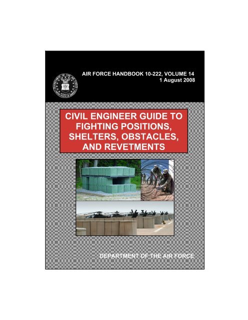
CIVIL ENGINEER GUIDE TO<br />
FIGHTING POSITIONS,<br />
SHELTERS, OBSTACLES,<br />
AND REVETMENTS<br />
DEPARTMENT OF THE AIR FORCE
This Page Intentionally Left Blank
BY ORDER OF THE AIR FORCE HANDBOOK 10-222, VOLUME 14<br />
SECRETARY OF THE AIR FORCE 1 August 2008<br />
Certified Current, 8 March 2012<br />
Operations<br />
CIVIL ENGINEER GUIDE TO FIGHTING POSITIONS, SHELTERS,<br />
OBSTACLES, AND REVETMENTS<br />
______________________________________________________________<br />
ACCESSIBILITY: This publication is available on the e-Publishing<br />
website at http://www.e-publishing.af.mil for downloading and ordering.<br />
RELEASABILITY: There are no releasability restrictions.<br />
______________________________________________________________<br />
OPR: HQ AFCESA/CEXX Certified by: HQ AF/A7CX<br />
(Colonel Donald L. Gleason)<br />
Pages: 157<br />
Supersedes: AFH 10-222V14, 1 November 2000<br />
______________________________________________________________<br />
This handbook addresses expedient construction and employment of <strong>fighting</strong><br />
<strong>positions</strong>, <strong>shelters</strong>, <strong>obstacles</strong>, and revetments in the expeditionary environment.<br />
It is designed as a reference for deployed civil <strong>engineer</strong>s. The defensive<br />
measures are primarily intended for protection against conventional weapons<br />
effects. It is applicable <strong>to</strong> active duty, Air National Guard, and Air Force Reserve<br />
<strong>engineer</strong>s. Refer recommended changes and questions about this publication<br />
<strong>to</strong> the Office of Primary Responsibility (OPR) using the AF IMT 847,<br />
Recommendation for Change of Publication; route AF Its 847 from the field<br />
through Major Command (MAJCOM) publications/forms managers. Ensure<br />
all records created as a result of processes prescribed in this publication are<br />
maintained in accordance with AFMAN 33-363, Management of Records,<br />
and disposed of in accordance with the Air Force Records Disposition Schedule<br />
(RDS) at https://afrims.amc.af.mil. The use of the name or mark of any<br />
specific manufacturer, commercial product, commodity, or service in this<br />
publication does not imply endorsement by the Air Force.
AFH 10-222 Volume 14 1 August 2008 2<br />
SUMMARY OF CHANGES<br />
This publication has been substantially revised and must be completely reviewed.<br />
This revision removes obsolete force protection measures and incorporates<br />
the latest tactics, techniques, and procedures used by civil <strong>engineer</strong>s<br />
<strong>to</strong> implement physical security measures in the expeditionary environment.<br />
Preface. ...…………………………………………………………………..10<br />
Chapter 1—INTRODUCTION. .................................................................11<br />
1.1. Overview. ............................................................................... 11<br />
Figure 1.1. His<strong>to</strong>ric Earthworks. …………...................................................11<br />
1.2. The Threat. ............................................................................. 12<br />
Table 1.1. Typical Weapons and Their Effects. .......................................... 12<br />
Figure 1.2. Pressure-Time Curve. ............................................................... 13<br />
1.3. Planning. ................................................................................ 15<br />
1.4. Protective Construction. ......................................................... 19<br />
Figure 1.3. Protective Shelter Construction. ............................................... 19<br />
Table 1.2. Security Engineering Series of Unified Facilities Criteria. ..........20<br />
Chapter 2—FIGHTING POSITIONS. ..........………………....................21<br />
2.1. Overview. ............................................................................... 21<br />
2.2. Safety. .................................................................................... 21<br />
2.3. Materials. . .............................................................................. 21<br />
Table 2.1. Checklist – Basic Criteria for Fighting Positions. ...................... 22<br />
2.4. Hasty Fighting Positions. . ...................................................... 23<br />
Figure 2.1. Hasty Fighting Position. ............................................................ 24<br />
2.5. Deliberate Fighting Positions. ................................................ 24<br />
Figure 2.2. One-Person Deliberate Fighting Position. ................................. 25
AFH 10-222 Volume 14 1 August 2008 3<br />
Figure 2.3. Outlining One-Person Fighting Position. .................................. 26<br />
Figure 2.4. Grenade Sump – One-Person Fighting Position. .. .................... 27<br />
Figure 2.5. Fighting Position Revetment. ......................................................28<br />
Figure 2.6. Reinforced Trenches. ................................................................ 30<br />
Figure 2.7. Ground Shock Intercept Trenches. ............................................ 30<br />
Table 2.2. Checklist – Fighting Position Revetments and Trenches. . ......... 31<br />
Table 2.3. Timber and Processed Lumber Comparison. ............................. 33<br />
Figure 2.8. Placement of Roof Support Logs. ............................................. 33<br />
Table 2.4. Center-<strong>to</strong>-Center Spacing for Wood Stringers and Soil Cover <strong>to</strong><br />
Defeat Contact Bursts. ................................................................................ 34<br />
Figure 2.9. Illustration of Unsupported Span and On-Center Spacing. ....... 35<br />
Figure 2.10. Dustproof Layer. ..................................................................... 35<br />
Figure 2.11. Completed Fighting Position – Side View. ............................. 36<br />
Table 2.5. Checklist – Fighting Position Overhead Cover. . ........................ 37<br />
Figure 2.12. Two-Person Deliberate Fighting Position. .............................. 39<br />
Figure 2.13. Grenade Sumps – Two-Person Deliberate Fighting Position. ..40<br />
Figure 2.14. Typical Sec<strong>to</strong>rs of Fire. ........................................................... 42<br />
Figure 2.15. Curved Two-Person Deliberate Fighting Position. ...................42<br />
Figure 2.16. Basic Machine Gun Fighting Position. ................................... 43<br />
Figure 2.17. Top View – Three-Person Machine Gun Fighting Position. ... 44<br />
Figure 2.18. Rear View – Three-Person Machine Gun Fighting Position. .. 44<br />
Figure 2.19. L-Shaped Machine Gun Fighting Position. ............................. 45<br />
Figure 2.20. Horseshoe-Shaped Machine Gun Fighting Position. .............. 45<br />
Figure 2.21. Mortar Position. ...................................................................... 46
AFH 10-222 Volume 14 1 August 2008 4<br />
Figure 2.22. Light Antitank Weapon (LAW) Fighting Position. ................ 47<br />
Figure 2.23. Earth Containers Being Expanded and Filled On-site. ........... 48<br />
Figure 2.24. Improved Foundation. ............................................................. 49<br />
Figure 2.25. First Layer – Single-Bay Fighting Position. ............................ 50<br />
Figure 2.26. Second Layer – Single-Bay Fighting Position. ........... ............ 51<br />
Figure 2.27. Composite Panels – Single-Bay Fighting Position. ................. 51<br />
Figure 2.28. Waterproof Membrane – Single-Bay Fighting Position. ......... 52<br />
Figure 2.29. Overhead Cover – Single-Bay Fighting Position. ................... 53<br />
Figure 2.30. Completed Single–Bay Fighting Position. .............................. 53<br />
Chapter 3—PROTECTIVE STRUCTURES. ...........................................54<br />
3.1. Overview. ............................................................................... 54<br />
Figure 3.1. Protective Structures. .. .............................................................. 54<br />
3.2. Expedient Protective Structures. ............................................ 55<br />
Figure 3.2. Corrugated Metal Culvert Shelter. ............................................ 56<br />
Figure 3.3. Top View – Fighting Bunker. .. ................................................. 58<br />
Figure 3.4. Front View – Fighting Bunker. ...................................................58<br />
Figure 3.5. Layout and Design – Fighting Bunker. ..................................... 59<br />
Table 3.1. Fighting Bunker Bill of Materials. .. ........................................... 60<br />
Table 3.2. Thickness of Wood <strong>to</strong> Support Earth Cover. .............................. 60<br />
3.3. Prefabricated Structures. ........................................................ 61<br />
Figure 3.6. Expandable Tactical Shelter. .................................................... 61<br />
Figure 3.7. ISO Bunker. .............................................................................. 62<br />
Figure 3.8. First Layer – ISO Bunker. ......................................................... 63
AFH 10-222 Volume 14 1 August 2008 5<br />
Figure 3.9. Second Layer – ISO Bunker. ..................................................... 64<br />
Figure 3.10. Roof Support – ISO Bunker. ................................................... 65<br />
Figure 3.11. Sheet Piling – ISO Bunker. ..................................... ................ 66<br />
Figure 3.12. Waterproof Membrane – ISO Bunker. .....................................66<br />
Figure 3.13. Overhead Cover – ISO Bunker. .............................................. 67<br />
Table 3.3. Visual Checklist – ISO Bunker. .................................................. 67<br />
3.4. Reinforced Concrete Bunkers. ..... .......................................... 68<br />
Figure 3.14. Reinforced Concrete Bunkers. .................................. .............. 69<br />
Chapter 4—OBSTACLES. ....................................................................... 70<br />
4.1. Overview. ............................................................................... 70<br />
4.2. Planning. .... ............................................................................ 70<br />
4.3. Natural Obstacles. .................................................................. 71<br />
Figure 4.1. Existing Barrier Complemented With Barbed Wire. ..................71<br />
Table 4.1. Description of Natural Obstacles. ............................................... 72<br />
4.4. Field Expedient Obstacles. ..................................................... 73<br />
Figure 4.2. Abatis. ................... .................................................................... 73<br />
Figure 4.3. Log Wall. ................... ............................................................... 74<br />
Figure 4.4. Log Hurdles. ................... .......................................................... 75<br />
Figure 4.5. Log Cribs. ................... .............................................................. 76<br />
Figure 4.6. Timber Posts. ................... ......................................................... 77<br />
Figure 4.7. Steel Angled Posts. ................... ................................................ 78<br />
Figure 4.8. Berms and Ditches. ................... ................................................ 80<br />
Figure 4.9. Employing Additional Obstacles With Triangular Ditch. ......... 81
AFH 10-222 Volume 14 1 August 2008 6<br />
Figure 4.10. Earth-Filled Obstacles. ............................................................ 82<br />
Figure 4.11. Urban Rubble. ......................................................................... 83<br />
Figure 4.12. Concertina Wire Roadblock. ................................................... 84<br />
Table 4.2. Installation Procedures – Concertina Wire Roadblock. .............. 85<br />
Table 4.3. Installation Procedures – Triple-Strand Concertina Wire Fence. 86<br />
Figure 4.13. Picket Spacing. ........................................................................ 87<br />
Figure 4.14. Joining Rolls of Concertina Wire. ........................................... 87<br />
4.5. Prefabricated Obstacles. ......................................................... 88<br />
Figure 4.15. Fence Reinforced With Cable. ............... ................................. 88<br />
Figure 4.16. Obscuration Screen on Perimeter Fence. ........... ..................... 89<br />
Figure 4.17. Prede<strong>to</strong>nation Screening. ........... ............................................. 90<br />
Figure 4.18. Concrete Barriers. ........... ........................................................ 91<br />
Figure 4.19. Portable Lift Barrier. ............................................................... 93<br />
Figure 4.20. Retractable Bollards. ............................................................... 93<br />
Figure 4.21. Jersey Barrier. ......... ................................................................ 94<br />
Figure 4.22. Fixed Bollards. ........................................................................ 95<br />
Figure 4.23. Removable Posts. .................................................................... 96<br />
Figure 4.24. Typical Concrete Cube and Cylinder. ..................................... 97<br />
Figure 4.25. Tetrahedrons and Dragon’s Teeth. .......................................... 97<br />
Figure 4.26. Steel Hedgehog. .... .................................................................. 98<br />
Chapter 5—REVETMENTS. ................................................................... 99<br />
5.1. Overview. ............................................................................... 99<br />
Figure 5.1. Various Types of Revetments. ........ .......................................... 99
AFH 10-222 Volume 14 1 August 2008 7<br />
5.2. Berms. .................................................................................. 100<br />
Figure 5.2. Berm Height. ........................................................................... 101<br />
Figure 5.3. Berm Thickness. ........ ............................................................. 101<br />
Figure 5.4. Berm Slope. .... ........................................................................ 102<br />
Figure 5.5. Illustration of Berms With Varying Slopes. ............................ 103<br />
Figure 5.6. Structurally Supported Berm. ........ ......................................... 104<br />
Figure 5.7. Structural Support for Berms. ........ ......................................... 105<br />
Figure 5.8. Berm Supported by Revetments. ............................................. 106<br />
Figure 5.9. Berm Supported by a Facility. ................................................ 106<br />
Figure 5.10. Berms Supported by Retaining Walls. .................................. 107<br />
5.3. Sandbag Revetments. ........................................................... 108<br />
Table 5.1. Sandbag National S<strong>to</strong>ck Numbers. ........................................... 108<br />
Figure 5.11. Sandbag Revetment Close <strong>to</strong> Protected Asset. ...................... 109<br />
Figure 5.12. Sandbag Revetment Built Against a Structure. ..................... 109<br />
Figure 5.13. Expedient Sandbag Filler. ..................................................... 110<br />
Figure 5.14. Sandbag Revetments – Layout and Construction. ................. 111<br />
Figure 5.15. Sandbags Reinforcing Existing Revetments. ... ..................... 112<br />
5.4. Metal Revetments. ............................................................... 113<br />
Figure 5.16. B-1 Revetment. ....... .............................................................. 113<br />
Figure 5.17. Corrugated Galvanized Steel Revetments. ............................ 114<br />
Table 5.2. Specifications and Ordering Information. ....... ......................... 114<br />
5.5. Precast Concrete Revetments. .............................................. 115<br />
Figure 5.18. Precast Concrete Revetment. ....... ......................................... 115
AFH 10-222 Volume 14 1 August 2008 8<br />
5.6. Precast Concrete Wall. ......................................................... 116<br />
Figure 5.19. Precast Concrete Wall. .......................................................... 116<br />
5.7. Soil–Cement Revetments. .................................................... 117<br />
Figure 5.20. Soil–Cement Revetment. ...................................................... 117<br />
5.8. Concrete Culverts. ................................................................ 118<br />
Figure 5.21. Concrete Culvert Soil Bin. .................................................... 118<br />
5.9. Timber and Lumber Revetments. ......................................... 119<br />
Figure 5.22. Timber and Lumber Revetments. .......................................... 119<br />
5.10. Sand Grid Revetments. ...................................................... 120<br />
Figure 5.23. Sand Grid Revetment Construction. ..................................... 120<br />
5.11. Earth-Filled Container Revetments. ................................... 121<br />
Figure 5.24. Earth-Filled Container Revetment – First Layer. .................. 122<br />
Figure 5.25. Coil Hinges and Connecting Pin. .......................................... 122<br />
Figure 5.26. Earth-Filled Container Revetment – Second Layer. ............. 122<br />
5.12. Siting Revetments. ............................................................. 123<br />
Table 5.3. Principles for Siting Large Structural Revetments. .................. 123<br />
Figure 5.27. Improperly Sited Revetment. ................................................ 124<br />
Figure 5.28. Properly Sited Revetment. .................................................... 124<br />
Figure 5.29. Dispersed Pattern for Aircraft Revetments. .......................... 125<br />
Figure 5.30. Clustered Patterns for Aircraft Revetments. ......................... 126<br />
Figure 5.31. General Examples of Siting Revetments. .............................. 127<br />
Attachment 1—GLOSSARY OF REFERENCES AND SUPPORTING<br />
INFORMATION. ………………………………………………………...129<br />
Attachment 2—PROTECTIVE MATERIALS. ......................................139
AFH 10-222 Volume 14 1 August 2008 9<br />
Attachment 3—FIELD CLASSIFICATION OF SOILS. ......................144
AFH 10-222 Volume 14 1 August 2008 10<br />
Preface<br />
Force protection is a commander’s <strong>to</strong>p priority in any military operation. For<br />
this reason, civil <strong>engineer</strong>s must always be aware of the latest tactics, techniques,<br />
and procedures (TTPs) used <strong>to</strong> protect our forces, particularly in hostile<br />
environments. Engineers implement physical security measures <strong>to</strong> protect<br />
personnel and critical assets needed <strong>to</strong> achieve military objectives. To assist<br />
in these efforts, this handbook is intended <strong>to</strong> be a reference for constructing<br />
and employing expedient <strong>fighting</strong> <strong>positions</strong>, <strong>obstacles</strong>, <strong>shelters</strong>, and revetments.<br />
It focuses primarily upon measures <strong>engineer</strong>s can employ <strong>to</strong> protect<br />
airbases and mitigate the effects of direct- and indirect-fired weapons. This<br />
handbook should be used in conjunction with AFH 10-222, Volume 3, <strong>Civil</strong><br />
Engineer Guide <strong>to</strong> Expeditionary Force Protection, as well as other 10-222<br />
series AF Handbooks and 10-219 series AF Pamphlets. Although many of the<br />
TTPs described are designed <strong>to</strong> protect critical resources through hardening<br />
and the use of <strong>obstacles</strong>, commanders must not lose sight of the fact that<br />
standoff provides the best chance of success in protecting the force. In addition<br />
<strong>to</strong> the information contained in the aforementioned publications, civil<br />
<strong>engineer</strong>s should be familiar with the security <strong>engineer</strong>ing series of Unified<br />
Facilities Criteria (UFC) and the latest guidance provided by those organizations<br />
constantly testing materials and designs <strong>to</strong> provide better protection for<br />
our military forces. These include organizations such as the Air Force Research<br />
Labora<strong>to</strong>ry (AFRL) and the US Army Corps of Engineers (USACE)<br />
Protective Design Center (PDC). This handbook does not address TTPs designed<br />
<strong>to</strong> defeat the vehicle-borne improvised explosive device (VBIED)<br />
threat. The Air Force Battlelab, through extensive testing, developed an excellent<br />
handbook for this purpose. AFH 10-2401, Vehicle Bomb Mitigation<br />
Guide (FOUO), focuses on the threat of VBIED attacks and describes the<br />
latest TTPs that can be employed <strong>to</strong> defeat this tactic. This handbook does not<br />
contain information for designing collective protection <strong>shelters</strong>. This information<br />
can be found in AFMAN 10-2502 series publications and USACE Engineering<br />
Technical Letters (ETLs) 1110-3-490 and 1110-3-498. USACE ETLs<br />
can be downloaded from http://www.usace.army.mil/.
AFH 10-222 Volume 14 1 August 2008 11<br />
Chapter 1<br />
INTRODUCTION<br />
1.1. Overview. Although tactics, techniques, and procedures (TTPs) used in<br />
modern warfare have evolved throughout his<strong>to</strong>ry, the basic concepts of defense<br />
and the use of earthworks remain critical elements of force protection<br />
(FP). His<strong>to</strong>rically, earthworks consisted of three parts: a ditch or trench, a<br />
short mound of earth material (a parapet) on the enemy side of the ditch <strong>to</strong><br />
disrupt the enemy’s flow, and a higher mound on the defenders’ side of the<br />
ditch for protection and <strong>to</strong> cover troop movements (Figure 1.1). Earthworks<br />
were often reinforced with wood, s<strong>to</strong>ne, and rocks and fortified with stakes <strong>to</strong><br />
provide additional <strong>obstacles</strong> <strong>to</strong> slow down the enemy’s approach or defend<br />
against larger weapons like the catapult and cannon. This concept of defense<br />
and other methods of fortification carry over <strong>to</strong> modern uses of earthworks.<br />
The TTPs covered in this handbook relate <strong>to</strong> the construction and employment<br />
of defensive <strong>fighting</strong> <strong>positions</strong>, protective <strong>shelters</strong>, <strong>obstacles</strong>, and revetments.<br />
Although the TTPs are aimed at mitigating the effects of blast and<br />
fragmentation effects from conventional weapons, many of these measures<br />
can also provide protection against the effects of nuclear weapons. However,<br />
refer <strong>to</strong> AFTTP(I) 3-2.46, Multiservice Tactics, Techniques, and Procedures<br />
for Nuclear, Biological, and Chemical (NBC) Protection, for guidance on<br />
constructing <strong>fighting</strong> <strong>positions</strong> and using existing <strong>shelters</strong> for protection<br />
against NBC effects. Before protective measures can be employed effectively<br />
in an expeditionary environment, it is necessary <strong>to</strong> understand the threat.<br />
Figure 1.1. His<strong>to</strong>ric Earthworks.
AFH 10-222 Volume 14 1 August 2008 12<br />
1.2. The Threat. Direct- and indirect-fired weapons are common threats <strong>to</strong><br />
airbases. Direct-fired weapons are projectiles designed <strong>to</strong> penetrate exterior<br />
protection. These weapons are highly accurate and capable of firing different<br />
types of projectiles including: (1) chemical or kinetic energy projectiles, (2)<br />
ball or tracer rounds, and (3) armor piercing rounds or high explosive shaped<br />
charges. Indirect-fired weapons include mortars, artillery shells, rockets, and<br />
bombs. These types of weapons are highly mobile and easily concealed. They<br />
can be fired from launchers or set on timers <strong>to</strong> allow aggressors time <strong>to</strong> escape<br />
prior <strong>to</strong> launch. Indirect-fired weapons do not require a clear line of<br />
sight <strong>to</strong> a specific target; aggressors rely on blast and fragmentation effects <strong>to</strong><br />
damage or destroy their intended targets. Table 1.1 lists typical weapons and<br />
describes their effects. Planners must consider these potential threats.<br />
Table 1.1. Typical Weapons and Their Effects.<br />
Weapon<br />
Projectiles: small arms and aircraft<br />
Effects<br />
cannons, direct- and indirect-fired<br />
projectiles, grenades, etc.<br />
Penetration, spalling, blast, fragmentation.<br />
Bombs: high-explosive (HE), fire and<br />
incendiary, dispenser, cluster, etc.<br />
Blast, fragmentation, target penetration,<br />
ground shock, cratering, ejecta, extreme<br />
heat and fire.<br />
Rockets and Missiles: Tactical and Target penetration, blast, fragmentation,<br />
battlefield support weapons, etc. ground shock, cratering, and ejecta.<br />
Special Purpose Weapons: Fuel-air Airblast, intense heat, noxious gases, oxy-<br />
munitions, incendiary, demolition gen deprivation, in-structure shock, crater-<br />
charges, etc.<br />
ing, ground shock.<br />
1.2.1. Blast and Fragmentation Effects. Exploding munitions produce extreme<br />
hazards such as blast and fragmentation. Mitigating the effects of these<br />
weapons must be a <strong>to</strong>p priority for civil <strong>engineer</strong>s during contingencies. Beddown<br />
and sustainment efforts might become futile if the force itself is vulnerable<br />
<strong>to</strong> a potentially devastating attack. Blast and fragmentation effects are<br />
briefly described in the following paragraphs.
AFH 10-222 Volume 14 1 August 2008 13<br />
1.2.1.1. Blast Effects. Explosive charges release an enormous amount of energy<br />
instantaneously through thermal radiation and shock waves. The shock<br />
wave is a compression wave that causes the atmospheric pressure <strong>to</strong> rise<br />
(overpressure) and peak in a fraction of a microsecond, followed by a slower<br />
(hundredths of a second) decline in atmospheric pressure, referred <strong>to</strong> as the<br />
positive phase of the shock wave. The pressure continues <strong>to</strong> decline <strong>to</strong> subatmospheric<br />
pressure (negative phase of the shock wave), and then returns <strong>to</strong><br />
normal (Figure 1.2). The positive impulse (intense pressure), represented by<br />
the area below the positive phase of the pressure-time curve, causes serious<br />
damage and destruction. It is important <strong>to</strong> know that blasts from highexplosive<br />
shells or rockets occur in three distinct ways: (1) overhead burst<br />
from artillery, which can destroy structures from the <strong>to</strong>p; (2) contact burst;<br />
artillery shells that explode upon impact, causing excavations and other structures<br />
<strong>to</strong> collapse from ground shock or foundation instability; and (3) delay<br />
fuze bursts, which are projectiles designed <strong>to</strong> penetrate a target before de<strong>to</strong>nating.<br />
Information on the effects of blasts on all types of structures can be<br />
found on the USACE PDC website at https://pdc.usace.army.mil.<br />
Figure 1.2. Pressure-Time Curve.
AFH 10-222 Volume 14 1 August 2008 14<br />
1.2.1.2. Fragmentation Effects. Fragmentation effects of weapons are characterized<br />
as either primary or secondary fragmentation. Fragmenting weapons<br />
are designed <strong>to</strong> propel debris from their casings (primary fragmentation) <strong>to</strong>wards<br />
a target <strong>to</strong> damage or destroy it. Secondary fragmentation is caused<br />
when the force of a blast causes objects <strong>to</strong> break apart, propelling additional<br />
debris <strong>to</strong>wards critical assets at extremely high velocities. The following<br />
paragraphs explain these effects in more detail.<br />
1.2.1.2.1. Primary Fragmentation. Primary fragmentation is caused by the<br />
breakup or shattering of weapon casings upon de<strong>to</strong>nation. The steel casings<br />
of fragmenting weapons are designed <strong>to</strong> produce a mass amount of debris<br />
traveling at a high rate of speed (thousands of feet per second) when the projectile<br />
de<strong>to</strong>nates and disintegrates. Fragmentation effects caused by de<strong>to</strong>nation<br />
of a high-explosive bomb have a greater effective range than blast effects.<br />
These types of weapons are very effective against unprotected personnel<br />
and other soft targets. The destructive power of fragmenting weapons is<br />
maximized by using bombs specifically designed <strong>to</strong> achieve this effect or by<br />
using bombs with airburst functioning fuzes. Although fragmentation effects<br />
can be mitigated by well-designed obstructions on the ground, planners must<br />
also consider the effect of a direct hit or an airburst.<br />
1.2.1.2.2. Secondary Fragmentation. Secondary fragmentation is caused<br />
when blast pressure from a weapon de<strong>to</strong>nation exerts enough force upon existing<br />
structures in close proximity <strong>to</strong> cause the structure <strong>to</strong> break apart and<br />
become additional projectiles traveling at high rates of speed. Although it<br />
may be impractical <strong>to</strong> harden temporary structures <strong>to</strong> resist the effects of blast<br />
or fragmentation without sufficient standoff, properly constructed protective<br />
structures such as berms and revetments can provide some degree of protection<br />
without posing the risk of becoming fragmentation hazards themselves.<br />
To be effective, berms and revetments must be properly sited in relation <strong>to</strong><br />
the assets they are intended <strong>to</strong> protect. Siting and constructing berms and revetments<br />
are covered in more detail in Chapter 5 of this handbook.
AFH 10-222 Volume 14 1 August 2008 15<br />
1.3. Planning. <strong>Civil</strong> <strong>engineer</strong>s must develop plans <strong>to</strong> employ physical security<br />
measures designed <strong>to</strong> mitigate the effects of an enemy attack. This is a<br />
unique challenge in the expeditionary environment, since mobility assets are<br />
usually not designed <strong>to</strong> be capable of withstanding attacks from different<br />
types of weapons. For this reason, standoff, modern application of earthworks,<br />
and other expedient methods are used <strong>to</strong> counter known threats.<br />
1.3.1. Planning Fac<strong>to</strong>rs. Some key fac<strong>to</strong>rs <strong>engineer</strong>s consider while planning<br />
for physical security include desired levels of protection, potential threats,<br />
criticality and vulnerability assessments, and acceptable levels of risk. In addition,<br />
planners must take in<strong>to</strong> account the type of structures <strong>to</strong> be deployed,<br />
available funding, existing infrastructure (including natural and manmade<br />
features), available standoff, and local resources available, such as contract<br />
support and indigenous construction materials. These fac<strong>to</strong>rs, and any others<br />
unique <strong>to</strong> the deployed location, form the basis for force protection planning.<br />
1.3.2. Levels of Protection. Physical security measures are employed <strong>to</strong> obtain<br />
certain levels of protection. These protection levels are usually based<br />
upon known threats and the results of intelligence and assessment reports. It<br />
is unrealistic <strong>to</strong> believe all assets can be protected and the threat completely<br />
eliminated. This perception causes valuable resources <strong>to</strong> be wasted or misallocated.<br />
Risk management is based on the assumption that some risks must be<br />
taken <strong>to</strong> ensure limited resources are applied against the highest priority assets<br />
first, rather than all assets equally. Criticality assessments usually result<br />
in the assignment of certain values <strong>to</strong> particular assets. They reveal the degree<br />
of debilitating impact that destruction of certain assets would have upon the<br />
mission; obviously, personnel come first. Unacceptable losses require higher<br />
levels of protection. Assets most critical <strong>to</strong> the mission must be afforded<br />
higher levels of protection, especially if vulnerability assessments indicate<br />
these assets are not already sufficiently protected. Different levels of protection<br />
are described in UFC 4-020-01, DOD Security Engineering Facilities<br />
Planning Manual. The following paragraphs cover the assessments usually<br />
conducted <strong>to</strong> assist commanders in determining levels of protection.
AFH 10-222 Volume 14 1 August 2008 16<br />
1.3.3. Threat Assessment. This assessment is used <strong>to</strong> identify threats based<br />
on key fac<strong>to</strong>rs such as the existence, capability, and intentions of potential<br />
hostile forces and terrorist groups. Group activities and the operational environment<br />
are also considered. Potential threats are categorized in various ways<br />
(e.g., terrorists, saboteurs, spies, extremists, criminals). Any weapons, <strong>to</strong>ols,<br />
and explosives likely <strong>to</strong> be used in an attack upon DOD personnel or critical<br />
assets are also identified during the assessment.<br />
1.3.4. Criticality Assessment. The criticality assessment is the process used<br />
<strong>to</strong> systematically identify key assets (e.g., personnel, equipment, s<strong>to</strong>ckpiles,<br />
buildings) deemed mission critical by commanders based on their importance<br />
<strong>to</strong> the mission or function. This assessment forms the basis for prioritizing<br />
assets requiring certain levels of protection. Commanders must consider all<br />
assets that need protection, all required protective measures, and all available<br />
resources (e.g., time, materials, personnel, equipment).<br />
1.3.5. Vulnerability Assessment. The vulnerability assessment is an evaluation<br />
conducted <strong>to</strong> determine if key assets are provided appropriate levels of<br />
protection. Protection levels are based on minimum standards where no specific<br />
threat has been identified or on higher levels of protection where a specific<br />
threat has been identified. This assessment analyzes the threat, likely<br />
tactics, and key targets that may be vulnerable <strong>to</strong> attack.<br />
1.3.6. Risk Assessment. Risk assessments help commanders make decisions<br />
on the most effective ways <strong>to</strong> allocate limited resources needed <strong>to</strong> protect<br />
personnel and critical assets. The assessment is based upon the results of the<br />
threat, criticality, and vulnerability assessments. Based on these assessments,<br />
the commander commits resources <strong>to</strong> achieve certain levels of protection for<br />
personnel and mission-critical assets. With limited resources, all assets cannot<br />
be afforded equal levels of protection. Risk Management provides the commander<br />
with the best information available <strong>to</strong> make resource allocation decisions.<br />
If plans do not incorporate these assessments, they will likely be <strong>to</strong>o<br />
reactive and cause limited resources <strong>to</strong> be misdirected or wasted. For additional<br />
information on the assessments used in determining levels of protection,<br />
refer <strong>to</strong> AFH 10-222, Volume 3, <strong>Civil</strong> Engineer Guide <strong>to</strong> Expeditionary<br />
Force Protection.
AFH 10-222 Volume 14 1 August 2008 17<br />
1.3.7. Resources. Planners must identify resources needed <strong>to</strong> implement security<br />
measures throughout all stages of deployments. A limited amount of<br />
resources usually drives the need <strong>to</strong> apply risk management <strong>to</strong> ensure the<br />
most critical assets are adequately protected. The following paragraphs cover<br />
the areas planners must consider.<br />
1.3.7.1. Funding. Funding for FP resources must be given the highest priority.<br />
Although civil <strong>engineer</strong>s may not be directly involved with funding decisions<br />
at the highest levels, it is important <strong>to</strong> know that the Chairman of the<br />
Joint Chiefs of Staff has access <strong>to</strong> a special fund, known as the Combating<br />
Terrorism Readiness Initiative Fund (CbTRIF). The CbTRIF is a jointservices<br />
fund designed <strong>to</strong> fund projects for emergent or high-priority force<br />
protection equipment or construction. These funds can be used <strong>to</strong> procure<br />
physical security equipment <strong>to</strong> reduce vulnerabilities. Requests for funding<br />
through this process must be for unanticipated requirements where the urgency<br />
for funding cannot be met through the normal Service funding process.<br />
However funds are obtained, ensure all FP requirements are clearly identified<br />
and address the exact purpose for which the requirements are needed, including<br />
vulnerabilities that commanders must addressed (unless classified).<br />
1.3.7.2. Materials and Equipment. Class IV materials (i.e., construction and<br />
barrier materials) are available through many sources, including the Defense<br />
Logistics Agency’s Defense Supply Centers at https://www.dla.mil. Planners<br />
should become familiar with these sources and the different types of construction<br />
materials that can be acquired. If construction materials and other<br />
equipment resources (e.g., earth-moving and material handling equipment)<br />
are not readily available in the deployed area, these items may need <strong>to</strong> be<br />
purchased and brought forward <strong>to</strong> establish some level of protection during<br />
initial beddown. Planners must also be aware that locally available materials<br />
and equipment may be of inferior quality, making it difficult <strong>to</strong> implement<br />
effective FP measures. When planning for materials and equipment, consider<br />
the possibility of increased threats that may require additional resources.<br />
Also, consider the possibility of pre-positioning FP resources at or near the<br />
site as war reserve materiel; this will provide the capability <strong>to</strong> quickly implement<br />
physical security measures in conjunction with initial beddown.
AFH 10-222 Volume 14 1 August 2008 18<br />
1.3.8. Training. Every effort must be made <strong>to</strong> ensure civil <strong>engineer</strong>s are sufficiently<br />
trained on physical security TTPs prior <strong>to</strong> deploying. Hands-on<br />
training is needed <strong>to</strong> ensure deploying personnel are proficient in constructing<br />
critical structures such as guard <strong>to</strong>wers, berms, ditches and protective <strong>shelters</strong>.<br />
There are several training venues available <strong>to</strong> assist civil <strong>engineer</strong>s prior<br />
<strong>to</strong> expeditionary deployments.<br />
1.3.8.1. US Army Corps of Engineers (USACE) Protective Design Center<br />
(PDC). The USACE PDC offers several training courses on security <strong>engineer</strong>ing<br />
and protective design. These courses are in-resident and range from<br />
two <strong>to</strong> eight days. Some courses cover the different software programs used<br />
<strong>to</strong> estimate blast effects. For example, the Blast Effects Estimation Model<br />
(BEEM) is an assessment <strong>to</strong>ol used <strong>to</strong> estimate facility damage and personnel<br />
injuries resulting from an attack. The BlastX software performs calculations<br />
of shock wave effects. Keep in mind, <strong>engineer</strong>s using this software must be<br />
extremely familiar with the different programs and their application <strong>to</strong> avoid<br />
miscalculating or misinterpreting specific outputs. Mobile Training Teams<br />
(MTTs) can also be scheduled <strong>to</strong> conduct security <strong>engineer</strong>ing courses at a<br />
unit’s home station. However, the unit must pay all expenses related <strong>to</strong> bringing<br />
MTTs <strong>to</strong> their location. The PDC also has an on-line open forum that<br />
allows members <strong>to</strong> post questions and receive information from <strong>engineer</strong>s<br />
who are experts in a variety of areas. For additional information, go <strong>to</strong> the<br />
PDC website at https://pdc.usace.army.mil.<br />
1.3.8.2. Theater Construction Management System (TCMS). TCMS is a<br />
PC-based au<strong>to</strong>mated construction planning, design, management, and reporting<br />
system that is used by military <strong>engineer</strong>s for contingency construction<br />
activities. Its primary purpose is <strong>to</strong> support OCONUS (outside the Continental<br />
United States) requirements. It combines state-of-the-art computer hardware<br />
and software with Army Facilities Component System (AFCS) design<br />
information <strong>to</strong> support and enhance the accomplishment of <strong>engineer</strong> mission<br />
activities in the theater of operation or other mission arenas. A wealth of information,<br />
including drawings and specifications for expeditionary structures,<br />
such a guard <strong>to</strong>wers, revetments, and various <strong>obstacles</strong>, can be retrieved<br />
through TCMS at http://www.tcms.net.
AFH 10-222 Volume 14 1 August 2008 19<br />
1.4. Protective Construction. Protective construction refers <strong>to</strong> the design,<br />
construction, and layout of facilities <strong>to</strong> support an integrated and in-depth<br />
plan <strong>to</strong> protect personnel and critical assets from enemy attack. From a civil<br />
<strong>engineer</strong> perspective, these efforts should be focused on activities related <strong>to</strong><br />
survivability. The mission cannot be successfully accomplished if the force is<br />
devastated by enemy attacks. Survivability, defined in JP 3-34, Engineer<br />
Doctrine for Joint Operations, involves a concept aimed at protecting all aspects<br />
of a military operation (e.g., personnel, weapons, supplies) while simultaneously<br />
maintaining the capability <strong>to</strong> deceive the enemy. Survivability tactics<br />
include building a strong defense; employing frequent movement tactics;<br />
using camouflage, concealment, and deception (CCD); and constructing<br />
<strong>fighting</strong> and protective <strong>positions</strong> for personnel and equipment (Figure 1.3).<br />
In addition <strong>to</strong> guidance provided in this handbook, several publications (classified<br />
FOUO) provide detailed guidance <strong>to</strong> ensure appropriate levels of protection<br />
are provided for key assets based on specific locations and threats.<br />
These documents, sometimes referred <strong>to</strong> as the security <strong>engineer</strong>ing series of<br />
UFCs, are listed in Table 1.2. In addition <strong>to</strong> UFCs, planners should be familiar<br />
with the latest TTPs outlined in the Joint Contingency Operations Base<br />
(JCOB) Force Protection Handbook and the Joint Forward Operations Base<br />
(JFOB) Force Protection Handbook. These documents can be downloaded<br />
from the Joint Staff Antiterrorism Portal (ATEP) website at<br />
https://atep.dtic.mil.<br />
Figure 1.3. Protective Shelter Construction.
AFH 10-222 Volume 14 1 August 2008 20<br />
Table 1.2. Security Engineering Series of Unified Facilities Criteria.<br />
Publication # Publication Title<br />
UFC 4-010-01 DOD Minimum Antiterrorism Standards for<br />
Buildings<br />
UFC 4-010-02 DOD Minimum Antiterrorism Standoff Distances for<br />
Buildings<br />
UFC 4-020-01FA DOD Security Engineering Facilities Planning<br />
Manual<br />
UFC 4-020-02FA DOD Security Engineering Facilities Design Manual<br />
UFC 4-020-03FA Security Engineering: Final Design<br />
UFC 4-021-01 Design and O&M: Mass Notification Systems<br />
UFC 4-021-02 Security Engineering: Electronic Security Systems<br />
UFC 4-022-01 Entry Control Facilities/Access Control Points<br />
UFC 4-022-02 Design and Selection of Vehicle Barriers<br />
UFC 4-022-03/ Design of Security Fencing, Gates, Barriers, and<br />
MIL-HDBK-1013/10 Guard Facilities<br />
UFC 4-023-03 Design of Buildings <strong>to</strong> Resist Progressive Collapse<br />
UFC 4-023-04 Design of Windows <strong>to</strong> Resist Blast, Ballistics, and<br />
Forced Entry<br />
UFC 4-023-07 Design <strong>to</strong> Resist Direct Fire Weapons Effects<br />
UFC 4-026-01 Design <strong>to</strong> Resist Forced Entry<br />
UFC 4-027-01 Design of Deployed Operational Bases <strong>to</strong> Mitigate<br />
Terrorist Attacks
AFH 10-222 Volume 14 1 August 2008 21<br />
Chapter 2<br />
FIGHTING POSITIONS<br />
2.1. Overview. Fighting <strong>positions</strong> are fortified structures used for protection<br />
against hostile fire. They can also be used as central points from which <strong>to</strong><br />
direct fire at offensive forces and provide overlapping fields of fire with adjacent<br />
<strong>fighting</strong> <strong>positions</strong>. The <strong>positions</strong> are constructed either hastily or deliberately,<br />
depending on the availability of time, materials, and the threat. Ideally,<br />
they should be sited <strong>to</strong> take advantage of natural terrain that conceals them<br />
and obscures direct lines of sight while providing a means <strong>to</strong> direct fire <strong>to</strong>wards<br />
the enemy. Overhead cover is constructed when time is not a fac<strong>to</strong>r.<br />
The most important point <strong>to</strong> remember when constructing a <strong>fighting</strong> position<br />
is <strong>to</strong> make sure it cannot be detected. Do not site these <strong>positions</strong> where the<br />
enemy expects <strong>to</strong> find them. Once detected, the “element of surprise” will be<br />
lost. Camouflage should be applied <strong>to</strong> these <strong>positions</strong> <strong>to</strong> further complicate<br />
the enemy’s ability <strong>to</strong> detect them. All of these tactics provide security forces<br />
with the capability needed <strong>to</strong> decisively eliminate attempts <strong>to</strong> penetrate camp<br />
boundaries or launch attacks upon military installations.<br />
2.2. Safety. Safety is paramount <strong>to</strong> constructing <strong>fighting</strong> <strong>positions</strong>. Personnel<br />
have been killed and injured as a result of improperly constructed <strong>fighting</strong><br />
<strong>positions</strong>. FM 5-34, Engineer Field Data, FM 5-103, Survivability, and Government<br />
Training Aid (GTA) 05-08-001, Survivability Positions, contain<br />
guidance for proper construction. Supervisors must ensure their personnel are<br />
trained on these procedures and should always supervise the actual construction.<br />
Once constructed, these <strong>positions</strong> must be inspected frequently, especially<br />
after the area experiences heavy rainfall and immediately after an attack.<br />
Table 2.1 contains basic criteria for constructing <strong>fighting</strong> <strong>positions</strong>.<br />
2.3. Materials. During contingencies, <strong>engineer</strong>s use whatever materials are<br />
available <strong>to</strong> construct and fortify <strong>fighting</strong> <strong>positions</strong>. Attachment 2 lists protective<br />
characteristics of some materials that can be used for these efforts<br />
along with information that can be used <strong>to</strong> determine the required thickness<br />
of materials needed <strong>to</strong> mitigate the effects of various types of weapons.
AFH 10-222 Volume 14 1 August 2008 22<br />
Table 2.1. Checklist - Basic Criteria for Fighting Positions.<br />
1 Construct <strong>fighting</strong> <strong>positions</strong> IAW FM 5-34 and GTA 05-08-001<br />
2 Use proper material; always follow proper construction procedures<br />
3 Make sure <strong>positions</strong> provide protection from direct enemy fire<br />
4 Position enables personnel <strong>to</strong> engage enemy with assigned sec<strong>to</strong>rs<br />
5 Do not site <strong>positions</strong> where the enemy expects <strong>to</strong> find them<br />
6 Site <strong>positions</strong> where they are concealed by natural barriers<br />
7 Site <strong>positions</strong> <strong>to</strong> provide for effective interlocking fires<br />
8 Camouflage <strong>positions</strong> <strong>to</strong> blend with the surrounding terrain<br />
9 Ensure <strong>positions</strong> are not be detectable from 35 meters (40 yards)<br />
10 Ensure occupants are not silhouetted against the surroundings<br />
11 Construct parapets at least 39 inches thick (length of an M-16 rifle)<br />
12 Construct parapets at least 12 inches high (length of a bayonet)<br />
13 Build front/flank/rear parapets one-helmet distance from the hole<br />
14 Revet excavations in areas with sandy soil <strong>to</strong> prevent collapse<br />
15 Use structural support for stringers; do not use sandbags for support<br />
16 Dig in structural supports approximately ½ their height/diameter<br />
17 Ensure stringers are spaced using guidance in GTA 05-08-001<br />
18 Check stabilization of wall bases and make needed adjustments<br />
19 Do not drive vehicles within 6 feet of <strong>positions</strong> in sandy soil<br />
20 Construct deliberate <strong>fighting</strong> <strong>positions</strong> approximately armpit deep<br />
21 Construct hasty <strong>fighting</strong> <strong>positions</strong> at least 18 inches deep<br />
22 Fill sandbags approximately 75 percent and tighten choke cords<br />
23 Provide at least 18 inches of cover <strong>to</strong> protect against indirect fire<br />
24 Provide additional cover as needed based on the threat<br />
25 Supervise construction and inspect <strong>fighting</strong> <strong>positions</strong> daily<br />
26 Maintain, repair, and improve <strong>fighting</strong> <strong>positions</strong> as time permits
AFH 10-222 Volume 14 1 August 2008 23<br />
2.4. Hasty Fighting Positions. Hasty <strong>fighting</strong> <strong>positions</strong> are used when time<br />
and materials are limited. They can be constructed using whatever objects or<br />
materials that inhabit the area (i.e., dirt, trees, logs, boulders, etc.). If an existing<br />
depression is available, it can be used as a hasty <strong>fighting</strong> position. Hasty<br />
<strong>fighting</strong> <strong>positions</strong> are constructed by digging a hole at least 18 inches deep for<br />
protection against indirect fire. The position should be able <strong>to</strong> accommodate<br />
the occupant, be at least 24 inches wide, and include parapets for frontal and<br />
flank cover. Ideally, the position is sited where natural cover from direct fire<br />
is available (i.e., trees, large rocks, rubble, etc.). This helps <strong>to</strong> conceal the<br />
position and make enemy detection difficult. If natural cover is not available,<br />
use the soil excavated from the hole or other fill material in the surrounding<br />
area <strong>to</strong> construct parapets. NOTE: Do not leave fresh soil exposed – the entire<br />
position must be camouflaged. Parapets should be at least 18 inches high,<br />
36 inches thick, and 6 inches (one-helmet distance) away from the hole. If<br />
logs are used instead of soil or sandbags, they must be held firmly in place<br />
with strong stakes 2 <strong>to</strong> 3 inches in diameter and approximately 18 inches<br />
long. Frontal cover is constructed for protection against small caliber direct<br />
fire. Flank and rear cover is used <strong>to</strong> mitigate the effects of indirect fire burst<br />
<strong>to</strong> the flank and rear. Hasty <strong>fighting</strong> <strong>positions</strong> can be set up quickly with little<br />
effort, but provide a minimum amount of protection. If properly located, and<br />
the unit will remain in the area, improve the position as time permits <strong>to</strong> include<br />
overhead cover. Use the basic criteria presented earlier in Table 2.1<br />
and FM 5-103 when constructing hasty <strong>fighting</strong> <strong>positions</strong>. The following<br />
paragraphs contain brief descriptions of various hasty <strong>fighting</strong> <strong>positions</strong>.<br />
2.4.1. Crater Positions. Crater <strong>positions</strong>, which are depressions in the ground<br />
caused by exploding shells or bombs, can provide protection under direct fire.<br />
These <strong>positions</strong> should be at least 2 <strong>to</strong> 3 feet wide and 18 inches deep. The<br />
trenching <strong>to</strong>ol is used <strong>to</strong> dig a steep face or parapet for added protection.<br />
2.4.2. Skirmisher’s Trench. A skirmisher’s trench can also provide immediate<br />
cover. This position requires troops <strong>to</strong> lie down in the prone position and<br />
use the entrenching <strong>to</strong>ol or other means <strong>to</strong> scrape the surrounding soil and<br />
build parapets between themselves and the direction of enemy fire.
AFH 10-222 Volume 14 1 August 2008 24<br />
2.4.3. Prone Position. The prone position, illustrated in Figure 2.1, is an<br />
improved skirmisher’s trench that conforms <strong>to</strong> the position and body length<br />
of its occupant. It serves as a good firing position and provides better protection<br />
from direct fire weapons than the crater or skirmisher’s trench. Parapets,<br />
18 inches in height, should be constructed around the position for protection<br />
against indirect fire. However, because this is essentially a hasty position,<br />
overhead cover is not usually constructed.<br />
Figure 2.1. Hasty Fighting Position.<br />
2.5. Deliberate Fighting Positions. Deliberate <strong>fighting</strong> <strong>positions</strong> are designed<br />
<strong>to</strong> accommodate personnel, their equipment, and certain weapons <strong>to</strong><br />
be employed from the position. These <strong>positions</strong> are more protective and<br />
should be constructed if a unit will be in a particular location for an extended<br />
time. Several types of deliberate <strong>fighting</strong> <strong>positions</strong> can be constructed based<br />
on (1) the weapon <strong>to</strong> be employed from the position, (2) the number of personnel<br />
that will occupy the position, and (3) the amount of gear and equipment<br />
the position must accommodate. Supervisors ensure <strong>positions</strong> are properly<br />
constructed and overlapping fields of fire are provided with adjacent<br />
<strong>fighting</strong> <strong>positions</strong>. The next few paragraphs describe procedures for constructing<br />
deliberate <strong>fighting</strong> <strong>positions</strong>. Although some guidance is provided<br />
here, refer <strong>to</strong> FM 5-103 for details on constructing intercepting trenches for<br />
<strong>fighting</strong> <strong>positions</strong> sited in areas that may experience ground shock.
AFH 10-222 Volume 14 1 August 2008 25<br />
2.5.1. One-Person Deliberate Fighting Position. One-person deliberate<br />
<strong>fighting</strong> <strong>positions</strong> (Figure 2.2) are constructed when time and materials are<br />
available and the tactical situation warrants additional protection. The excavation<br />
is relatively small, making it easier <strong>to</strong> use materials from the surrounding<br />
area for overhead cover and camouflage. This position must allow the<br />
individual <strong>to</strong> fire <strong>to</strong> the front and oblique while behind frontal cover. All of<br />
the basic construction criteria established for one-person deliberate <strong>fighting</strong><br />
<strong>positions</strong> also applies <strong>to</strong> <strong>fighting</strong> <strong>positions</strong> constructed on larger scales and<br />
for different reasons. Critical aspects of constructing a one-person deliberate<br />
<strong>fighting</strong> position will be covered first; variations <strong>to</strong> these basics will follow.<br />
Figure 2.2. One-Person Deliberate Fighting Position.<br />
2.5.1.1. Sec<strong>to</strong>rs of Fire. Sec<strong>to</strong>rs of fire are usually assigned by security personnel<br />
and form the basis for siting <strong>positions</strong>. If possible, select an area that<br />
will provide natural frontal cover protection from enemy direct fire. If natural<br />
cover is unavailable where the position is sited, construct parapets.
AFH 10-222 Volume 14 1 August 2008 26<br />
2.5.1.2. Aiming and Sec<strong>to</strong>r Stakes. Aiming and sec<strong>to</strong>r stakes can be emplaced<br />
<strong>to</strong> help security personnel with firing and <strong>to</strong> define sec<strong>to</strong>rs of fire. Outline<br />
the position as shown in Figure 2.3. For a one-person position, the hole<br />
is usually about the length of an M-16 (roughly 3 feet and 3 inches long) and<br />
as wide as two helmets (roughly 2 feet). NOTE: This usually is not done for<br />
hasty <strong>fighting</strong> <strong>positions</strong>.<br />
2.5.1.3. Parapets. Prepare parapet retaining walls using logs or other natural<br />
materials. If logs are used, stake them down firmly with stakes about 2 <strong>to</strong> 3<br />
inches in diameter and 18 inches long. The walls should be at least 6 inches<br />
(one-helmet distance) from the edge of the hole. Build the front wall first, at<br />
least two sandbags high (approximately 18 inches), 36 inches thick, and the<br />
length of two M-16s (approximately 6 feet and 6 inches long). Sandbags<br />
should be 75 percent full. Next, build flank walls with the same height and<br />
thickness as that of the front wall, with the length being approximately equal<br />
<strong>to</strong> that of one M-16. The rear wall should be one sandbag high and one M-16<br />
long. Dig the hole <strong>to</strong> armpit depth and slope the walls. Throw the excavated<br />
soil forward of the parapet retaining walls and pack it down hard.<br />
Figure 2.3. Outlining One-Person Fighting Position.
AFH 10-222 Volume 14 1 August 2008 27<br />
2.5.1.4. Grenade Sumps. Determining where <strong>to</strong> locate grenade sumps depends<br />
on the type of <strong>fighting</strong> position being constructed. For a one-person<br />
<strong>fighting</strong> position, grenade sumps (Figure 2.4) should be dug in<strong>to</strong> the bot<strong>to</strong>m<br />
front face of the position at approximately a 30-degree angle and 12 <strong>to</strong> 18<br />
inches deep, about the length of an entrenching <strong>to</strong>ol. The width of the sump<br />
should be approximately equal <strong>to</strong> the width of the entrenching <strong>to</strong>ol shovel.<br />
Use whatever <strong>to</strong>ols are available <strong>to</strong> slope the floor <strong>to</strong>wards the grenade sump.<br />
This will make it easier <strong>to</strong> kick a grenade in<strong>to</strong> the hole and get out of the way<br />
so the blast goes in<strong>to</strong> the back wall. For a larger, two-person <strong>fighting</strong> position,<br />
grenade sumps are usually dug at each end of the position <strong>to</strong> allow occupants<br />
<strong>to</strong> move <strong>to</strong>wards the opposite end away from the blast. Avoid locating<br />
grenade sumps under overhead cover, especially if the cover is constructed<br />
across the middle of the <strong>fighting</strong> position. The blast could reflect off<br />
the cover and cause injuries or collapse the entire structure. A combination of<br />
grenade sump trenches and holes can be used for special-purpose <strong>fighting</strong><br />
<strong>positions</strong>. A T-shaped position allows for additional observation or firing<br />
zones but may require additional grenade sumps. Make sure the blast from<br />
the sump is not directed <strong>to</strong>wards any occupied sections of the position.<br />
Figure 2.4. Grenade Sump – One-Person Fighting Position.
AFH 10-222 Volume 14 1 August 2008 28<br />
2.5.1.5. Fighting Position Revetments. In wet, sandy, or poorly compacted<br />
soils, revetments are used <strong>to</strong> reinforce the sides of <strong>fighting</strong> <strong>positions</strong> and<br />
trenches <strong>to</strong> prevent collapse (Figure 2.5). Revetting is also necessary when<br />
<strong>positions</strong> are dug in soils with large amounts of clay or high plasticity as<br />
these soils may liquefy, displace, or shear from ground shock. Without revetments,<br />
the walls of a position in sandy soils would have <strong>to</strong> be sloped <strong>to</strong><br />
achieve a certain depth. However, this is not recommended since the <strong>to</strong>p<br />
opening of the position would be <strong>to</strong>o wide, making it difficult <strong>to</strong> incorporate<br />
overhead cover. Revet <strong>fighting</strong> <strong>positions</strong> using material held in place with<br />
either braced or tied pickets. Pickets can be lumber, wooden poles, standard<br />
concertina wire pickets, metal poles, angular posts, or trees. Wooden pickets<br />
from trees or saplings should be at least 3 inches in diameter. The pickets are<br />
used <strong>to</strong> hold matting material (i.e., brushwood mats, lumber, wire mesh, geotextile<br />
fabric, cloth mat, etc.) against the soil face. More rigid facing materials<br />
include plywood, landing mats, corrugated metal, and timbers. Use the field<br />
expedient procedures outlined in Attachment 3 <strong>to</strong> classify soils and determine<br />
whether revetments are needed.<br />
Figure 2.5. Fighting Position Revetment.
AFH 10-222 Volume 14 1 August 2008 29<br />
2.5.1.6. Crawl Trenches. If time is available and the overall defensive posture<br />
needs <strong>to</strong> be enhanced, crawl trenches can be constructed <strong>to</strong> connect <strong>fighting</strong><br />
<strong>positions</strong> and prevent personnel from being exposed <strong>to</strong> enemy fire as they<br />
move about the area. The depth of these trenches is based on the availability<br />
of time and resources. Engineers will have <strong>to</strong> assist others with excavation<br />
and trench reinforcement (Figure 2.6). Crawl trenches should be dug in a<br />
zigzagged pattern <strong>to</strong> prevent the enemy from being able <strong>to</strong> fire down a long<br />
section if the trench is breached. This pattern will also help <strong>to</strong> reduce the effects<br />
of fragmentation if the crawl trench is hit with explosive munitions.<br />
2.5.1.7. Ground Shock Intercept Trenches. Since <strong>fighting</strong> <strong>positions</strong> might<br />
be needed in areas subject <strong>to</strong> high levels of ground shock based on certain<br />
soil or geological conditions, civil <strong>engineer</strong>s must have some general knowledge<br />
of geology and different soil types. Ground shock sufficient enough <strong>to</strong><br />
collapse <strong>fighting</strong> <strong>positions</strong> can occur when these <strong>positions</strong> are constructed<br />
over water tables <strong>to</strong>o close <strong>to</strong> the bot<strong>to</strong>m of the <strong>positions</strong> or in areas where the<br />
soil is located within 25 feet of and/or over an underlying rock formation,<br />
moist clay, or soils with high water content. Ground shock is intensified by<br />
reduced resistance through the soil or reflection from the underlying soil and<br />
rock formations. One way <strong>to</strong> reduce the effect of ground shock on <strong>fighting</strong><br />
<strong>positions</strong> involves constructing ground shock intercept trenches. Ground<br />
shock intercept trenches are meant <strong>to</strong> collapse from ground shock and thereby<br />
absorb enough of the ground shock <strong>to</strong> prevent <strong>fighting</strong> <strong>positions</strong> from collapsing.<br />
These types of trenches are dug approximately 12 inches wide <strong>to</strong> a depth<br />
that is at least 2 feet deeper than the <strong>fighting</strong> <strong>positions</strong> they are intended <strong>to</strong><br />
protect. They should also be at least 6 feet longer than the width of the <strong>fighting</strong><br />
position. Locate the trenches away from <strong>fighting</strong> <strong>positions</strong> at a distance<br />
approximately 1 1/2 <strong>to</strong> 2 times the depth of the trench, as illustrated in Figure<br />
2.7. Due <strong>to</strong> their narrow width, these trenches can easily be camouflaged.<br />
Table 2.2 can be used as a checklist <strong>to</strong> ensure revetments, crawl trenches, and<br />
ground shock intercept trenches are being properly constructed.
AFH 10-222 Volume 14 1 August 2008 30<br />
Figure 2.6. Reinforced Trenches.<br />
Figure 2.7. Ground Shock Intercept Trenches.
AFH 10-222 Volume 14 1 August 2008 31<br />
Table 2.2. Checklist - Fighting Position Revetments and Trenches.<br />
1<br />
2<br />
3<br />
4<br />
5<br />
6<br />
7<br />
8<br />
9<br />
10<br />
11<br />
12<br />
13<br />
14<br />
Use field soil sampling techniques (Attachment 3) <strong>to</strong> determine<br />
soil types and whether revetments will be required<br />
Use lumber, wooden poles, metal poles, concertina wire pickets,<br />
or trees as pickets <strong>to</strong> hold revetting material in place<br />
If wooden pickets from trees or saplings are used for pickets,<br />
ensure they are at least 3 inches in diameter<br />
Use flexible items such as brushwood mats, wire mesh, geotextile<br />
fabric, and cloth mats for facing material if available<br />
Use more rigid items such as corrugated metal sheets, landing<br />
mats, and lumber for facing material if available<br />
Space pickets based on soil type and facing material used (up <strong>to</strong><br />
30 inches for flexible material and 78 inches for rigid material)<br />
Drive pickets at least 18 inches in<strong>to</strong> the ground; use stakes <strong>to</strong><br />
help stabilize the pickets in place if needed<br />
Drive stakes in<strong>to</strong> the ground at a distance from the edge of the<br />
excavation equal <strong>to</strong> the depth of the excavation<br />
If more than 3 or 4 stakes are used, alternate the distance; place<br />
every other stake equal <strong>to</strong> the depth of the excavation plus 2 feet<br />
Consider the need <strong>to</strong> construct ground shock intercept trenches<br />
<strong>to</strong> absorb ground shock from explosions near <strong>fighting</strong> <strong>positions</strong><br />
If needed, construct ground shock intercept trenches between<br />
<strong>fighting</strong> <strong>positions</strong> and likely impact point for high explosives<br />
Dig intercept trenches at least 12 feet wide and at least 2 feet<br />
deeper than <strong>fighting</strong> <strong>positions</strong><br />
Dig intercept trenches at least 6 feet longer than the width of the<br />
<strong>fighting</strong> <strong>positions</strong> they are meant <strong>to</strong> protect<br />
Locate intercept trenches away from <strong>fighting</strong> <strong>positions</strong> at a horizontal<br />
distance of 1 1/2 <strong>to</strong> 2 times the depth of the trench
AFH 10-222 Volume 14 1 August 2008 32<br />
2.5.1.8. Fighting Position Overhead Protection and Cover. Fighting position<br />
overhead protection is used <strong>to</strong> mitigate the effects of blast and fragmentation<br />
from direct- and indirect-fired weapons. Cover provides concealment<br />
and protects against weather. Overhead protection and cover are always<br />
needed unless it will make the position easy <strong>to</strong> detect. The following paragraphs<br />
cover basic concepts for overhead protection and cover. Attachment<br />
2 contains information on thicknesses for protection against certain weapons.<br />
However, always reference FM 5-103, GTA 05-08-001, and GTA 07-06-001,<br />
Fighting Position Construction Infantry Leader’s Reference Card.<br />
2.5.1.8.1. Roof Supports. For standard one- and two-person <strong>fighting</strong> <strong>positions</strong>,<br />
4-inch x 4-inch x 6-foot lumber or timber equivalents are normally used<br />
for roof supports. To form the base structure for overhead cover, logs or lumber<br />
4 <strong>to</strong> 6 inches in diameter can be used. Table 2.3 compares cut timber <strong>to</strong><br />
the equivalent size of processed lumber. If logs are used, secure them with<br />
stakes approximately 2 <strong>to</strong> 3 inches in diameter and about 18 inches long.<br />
Make sure bearing support beams are properly positioned. Set support logs<br />
back a distance equal <strong>to</strong> approximately 1/4 the depth of the hole and embedded<br />
approximately halfway in<strong>to</strong> the ground as illustrated in Figure 2.8. Set<br />
overhead cover supports back about 1 foot or 1/4 the depth of the hole.<br />
2.5.1.8.2. Stringers. Stringers are made from solid and sturdy material, such<br />
as lumber or timber, and are used <strong>to</strong> support overhead cover. For standard<br />
one- and two-person <strong>fighting</strong> <strong>positions</strong>, 4-inch x 4-inch x 8-foot lumber or<br />
timber equivalents are normally used and spaced 6 inches on-center. Oncenter<br />
spacing is critical <strong>to</strong> the safety of <strong>fighting</strong> <strong>positions</strong>. If stringers are<br />
placed <strong>to</strong>o far apart, they will be less capable of carrying the dead weight of<br />
overhead cover. Stringer span (the unsupported distance between each end of<br />
material used as stringers) is also critical. Table 2.4, extracted from GTA 05-<br />
08-001, can be used <strong>to</strong> determine span and center-<strong>to</strong>-center spacing for woodsupporting<br />
soil cover <strong>to</strong> defeat various contact bursts. Figure 2.9 illustrates<br />
stringer placement for overhead cover. Ensure stringers are approximately the<br />
same size as roof supports, are laid side by side across them, extending at<br />
least 1-foot past the supports on each side of the <strong>fighting</strong> position.
AFH 10-222 Volume 14 1 August 2008 33<br />
Table 2.3. Timber and Processed Lumber Comparison.<br />
Cut Timber/Log Diameter Equivalent Size of Processed Lum-<br />
(inches)<br />
ber (inches)<br />
5 4 x 4<br />
7 6 x 6<br />
8 6 x 8<br />
10 8 x 8<br />
11 8 x 10<br />
12 10 x 10<br />
13 10 x 12<br />
14 12 x 12<br />
Figure 2.8. Placement of Roof Support Logs.
AFH 10-222 Volume 14 1 August 2008 34<br />
Table 2.4. Center-<strong>to</strong>-Center Spacing for Wood Stringers and Soil Cover<br />
<strong>to</strong> Defeat Contact Bursts.<br />
Nominal<br />
Stringer<br />
Size<br />
(inches)<br />
Depth of<br />
Soil, feet<br />
2x4 2 (0.6)<br />
3 (0.9)<br />
4 (1.2)<br />
2x6 2 (0.6)<br />
3 (0.9)<br />
4 (1.2)<br />
4x4 2 (0.6)<br />
3 (0.9)<br />
4 (1.2)<br />
4x8 1.5 (0.5)<br />
2 (0.6)<br />
3 (0.9)<br />
4x8 4.0 (1.2)<br />
5.0 (1.5)<br />
6.0 (1.8)<br />
6x6 4.0 (1.2)<br />
5.0 (1.5)<br />
6.0 (1.8)<br />
6x8 4.0 (1.2)<br />
5.0 (1.5)<br />
8x8 4.0 (1.2)<br />
5.0 (1.5)<br />
4x8 4.0 (1.2)<br />
5.0 (1.5)<br />
6.0 (1.8)<br />
7.0 (2.1)<br />
6x6 5.0 (1.5)<br />
6.0 (1.8)<br />
7.0 (2.1)<br />
6x8 4.0 (1.2)<br />
5.0 (1.5)<br />
6.0 (1.8)<br />
8x8 4.0 (1.2)<br />
5.0 (1.5)<br />
6.0 (1.8)<br />
Span Length, feet (meters)<br />
2 (0.6) 4 (1.2) 6 (1.8) 8 (2.4) 10 (3.0)<br />
Center <strong>to</strong> Center Stringer Spacing, inches (centimeters)<br />
(meters) 82-mm Contact Burst<br />
3 (7.6)<br />
18 (46)<br />
18 (46)<br />
4 (10)<br />
18 (46)<br />
18 (46)<br />
7 (18)<br />
18 (46)<br />
18 (46)<br />
4 (10)<br />
14 (36)<br />
18 (46)<br />
3.5 (9)<br />
12 (30)<br />
18 (46)<br />
--<br />
14 (36)<br />
18 (46)<br />
5.5 (14)<br />
18 (46)<br />
7.5 (19)<br />
18 (46)<br />
--<br />
6 (15)<br />
17 (43)<br />
18 (46)<br />
7 (18)<br />
18 (46)<br />
18 (46)<br />
--<br />
10 (25)<br />
18 (46)<br />
--<br />
14 (36)<br />
18 (46)<br />
4 (10)<br />
12 (30)<br />
14 (36)<br />
7 (18)<br />
18 (46)<br />
18 (46)<br />
10 (25)<br />
18 (46)<br />
18 (46)<br />
5 (13)<br />
18 (46)<br />
18 (46)<br />
4 (10)<br />
8 (20)<br />
7 (18)<br />
8 (20)<br />
16 (41)<br />
18 (46)<br />
10 (25)<br />
18 (46)<br />
18 (46)<br />
7 (18)<br />
18 (46)<br />
18 (46)<br />
4 (10)<br />
5 (13)<br />
4 (10)<br />
8 (20)<br />
12 (30)<br />
11 (28)<br />
9 (22)<br />
12 (30)<br />
10 (25)<br />
8 (20)<br />
18 (46)<br />
18 (46)<br />
120- and 122-mm Contact Burst<br />
4 (10)<br />
12 (30)<br />
18 (46)<br />
--<br />
14 (36)<br />
18 (46)<br />
6 (15)<br />
18 (46)<br />
9 (23)<br />
18 (46)<br />
--<br />
6 (15)<br />
16 (41)<br />
18 (46)<br />
8 (20)<br />
18 (46)<br />
18 (46)<br />
--<br />
11 (28)<br />
18 (46)<br />
--<br />
14 (36)<br />
18 (46)<br />
5 (13)<br />
12 (30)<br />
18 (46)<br />
5.5 (14)<br />
13 (33)<br />
18 (46)<br />
8 (20)<br />
18 (46)<br />
11 (28)<br />
18 (46)<br />
152-mm Contact Burst<br />
--<br />
7 (18)<br />
14 (36)<br />
18 (46)<br />
8 (20)<br />
15 (38)<br />
18 (46)<br />
--<br />
12 (30)<br />
18 (46)<br />
--<br />
16 (41)<br />
18 (46)<br />
5 (13)<br />
11 (28)<br />
16 (41)<br />
6 (15)<br />
12 (30)<br />
16 (41)<br />
9 (23)<br />
18 (46)<br />
12 (30)<br />
18 (46)<br />
--<br />
7 (18)<br />
12 (30)<br />
15 (38)<br />
8 (20)<br />
12 (30)<br />
15 (38)<br />
--<br />
12 (30)<br />
18 (46)<br />
--<br />
17 (43)<br />
18 (46)<br />
3 (8)<br />
3 (8)<br />
3 (8)<br />
6 (15)<br />
8 (20)<br />
7 (18)<br />
7 (18)<br />
8 (20)<br />
7 (18)<br />
8 (20)<br />
18 (46)<br />
18 (46)<br />
6 (15)<br />
10 (25)<br />
12 (30)<br />
6 (15)<br />
10 (25)<br />
12 (30)<br />
10 (25)<br />
18 (46)<br />
13 (33)<br />
18 (46)<br />
3.5 (9)<br />
7 (18)<br />
10 (25)<br />
11 (28)<br />
7 (18)<br />
10 (25)<br />
11 (28)<br />
6 (15)<br />
12 (30)<br />
17 (43)<br />
8 (20)<br />
16 (41)<br />
18 (46)
AFH 10-222 Volume 14 1 August 2008 35<br />
Figure 2.9. Illustration of Unsupported Span and On-Center Spacing.<br />
2.5.1.8.3. Dustproof Layer. Once the stringers are properly placed, put a<br />
dustproof layer over the base logs/stringers (Figure 2.10). The dustproof<br />
layer could be 4-feet by 4-feet sheets of 3/4-inch plywood. Nail the plywood<br />
dustproof layer <strong>to</strong> the stringers. This layer will also help <strong>to</strong> keep water from<br />
leaking through the overhead cover in<strong>to</strong> the <strong>fighting</strong> position.<br />
Figure 2.10. Dustproof Layer.
AFH 10-222 Volume 14 1 August 2008 36<br />
2.5.1.8.4. Cover. Place 6 <strong>to</strong> 8 inches of soil on <strong>to</strong>p of the dustproof layer<br />
(Figure 2.11). If sandbags are used, cover them with waterproof material as<br />
well. If they are drenched during rainy weather, sandbags will become very<br />
heavy and could cause roof supports <strong>to</strong> collapse.<br />
Figure 2.11. Completed Fighting Position – Side View.<br />
2.5.1.8.5. Inspection. Supervisors should have hands-on experience in constructing<br />
various types of <strong>fighting</strong> <strong>positions</strong>. There is no substitute for learning<br />
by doing. These leaders must be capable of inspecting <strong>fighting</strong> <strong>positions</strong><br />
during construction, after they are covered, before they are camouflaged, and<br />
again after they are camouflaged <strong>to</strong> ensure proper procedures are followed.<br />
The structure’s integrity must be approved before adding overhead cover and<br />
applying camouflage. In addition <strong>to</strong> GTA 05-08-001 and FM 5-103, Table<br />
2.5 can be used <strong>to</strong> ensure <strong>fighting</strong> <strong>positions</strong> are properly constructed.
AFH 10-222 Volume 14 1 August 2008 37<br />
Table 2.5. Checklist – Fighting Position Overhead Cover.<br />
1<br />
2<br />
3<br />
4<br />
5<br />
6<br />
7<br />
8<br />
9<br />
10<br />
11<br />
12<br />
13<br />
14<br />
Ensure GTA 05-08-001/07-06-001 are available for reference<br />
Construct <strong>fighting</strong> position overhead cover (4 feet in width)<br />
Use logs or lumber 4 <strong>to</strong> 6 inches in diameter for roof support<br />
Place roof supports 1/4 depth of the hole from edge of the hole<br />
Embed roof support logs/lumber ½ diameter in<strong>to</strong> the soil<br />
If logs or cut timber are used for roof supports, use stakes 2 <strong>to</strong> 3<br />
inches in diameter and 18 inches long <strong>to</strong> secure roof support<br />
Build front, flank, and rear parapets two sandbag layers high<br />
and 18 inches thick<br />
Place stringers (4 <strong>to</strong> 6 inches in diameter) on <strong>to</strong>p of roof support.<br />
Refer <strong>to</strong> Table 2.6 for stringer spacing<br />
Ensure stringers extend past roof supports and in<strong>to</strong> parapets<br />
(remove a portion of the parapets and place on <strong>to</strong>p of stringers)<br />
Place waterproof bags, ponchos, etc., on <strong>to</strong>p of the stringers<br />
Place 6 <strong>to</strong> 8 inches of packed dirt or sandbags on <strong>to</strong>p of the waterproof<br />
material<br />
If sandbags are used, place a water-resistant material over the<br />
sandbags <strong>to</strong> prevent them from becoming saturated<br />
Cover the dirt with sod, and camouflage the overhead cover<br />
Ensure the supervisor inspects the position upon completion and<br />
again daily, especially following bad weather or an attack
AFH 10-222 Volume 14 1 August 2008 38<br />
2.5.1.9. Concealment and Camouflage. The most important consideration in<br />
constructing <strong>fighting</strong> <strong>positions</strong> is making sure they cannot be detected. After<br />
overhead cover is constructed, use concealment and camouflage techniques <strong>to</strong><br />
make the position undetectable. Concealment is anything that hides the <strong>fighting</strong><br />
position from enemy observation. It may be natural material (i.e., bushes,<br />
leaves, grass, etc.) or artificial material (i.e., burlap, nets, etc.). If possible,<br />
locate <strong>fighting</strong> <strong>positions</strong> where natural cover, such as bushes, tall grass, trees,<br />
logs, stumps, mountainous terrain, or large rocks can help <strong>to</strong> conceal them.<br />
Take advantage of natural cover (i.e., wooded areas, hills, rock formations)<br />
for concealment, and cover shiny objects such as watches, compasses, and<br />
bayonets. Camouflage is used <strong>to</strong> blend the position with the surrounding terrain.<br />
The key <strong>to</strong> camouflaging <strong>fighting</strong> <strong>positions</strong> is <strong>to</strong> alter the appearance of<br />
the asset being protected in a manner where it becomes part of the background.<br />
Camouflage also makes use of natural and manmade material. Study<br />
the terrain and vegetation of the area. Natural cover could include materials<br />
such as trees, brush, grass, leaves, rocks, or boulders. When using natural<br />
cover for concealment, be careful not <strong>to</strong> disturb the look of the natural surroundings<br />
– use materials commonly found in the area where an asset is <strong>to</strong> be<br />
concealed. If vegetation/foliage is used <strong>to</strong> camouflage a position, it must be<br />
replaced before it dries and turns colors, making the position stand out in its<br />
surroundings. Since fresh soil can be used <strong>to</strong> detect a <strong>fighting</strong> position, it<br />
must be disposed of far away from the position. Be careful not <strong>to</strong> leave tracks<br />
leading <strong>to</strong> or from the position. Do not use <strong>to</strong>o much material; this could<br />
make the position stand out from its surroundings. Once the position is completed,<br />
inspect it from the enemy's viewpoint. As a final test of camouflage<br />
and concealment efforts, mark off 35 meters (38 yards) in the direction of the<br />
enemy and look back at the position <strong>to</strong> determine if it is undetectable and<br />
blends in with the surrounding area.
AFH 10-222 Volume 14 1 August 2008 39<br />
2.5.2. Two-Person Deliberate Fighting Position. Two-person deliberate<br />
<strong>fighting</strong> <strong>positions</strong> are most common. Basic requirements for these <strong>positions</strong><br />
are essentially the same as those for one-person <strong>fighting</strong> <strong>positions</strong> with key<br />
differences. Although this position is preferred, it is not without drawbacks.<br />
Two-person <strong>fighting</strong> <strong>positions</strong> require more digging and prove difficult <strong>to</strong><br />
camouflage. It also provides a better target for grenades because the excavation<br />
is larger. Typical combat gear such as the M-16 rifle and helmet can be<br />
used <strong>to</strong> measure dimensions (Figure 2.12). For example, the length of a twoperson<br />
<strong>fighting</strong> position can be measured using two M-16 rifles (approximately<br />
6 feet and 6 inches). The width can be measured with two helmets<br />
(approximately 2 feet). The following paragraphs describe details for constructing<br />
two-person <strong>fighting</strong> <strong>positions</strong>.<br />
Figure 2.12. Two-Person Deliberate Fighting Position.<br />
2.5.2.1. Sec<strong>to</strong>rs of Fire. Unlike the one-person deliberate <strong>fighting</strong> position,<br />
the two-person <strong>fighting</strong> position involves two fields of fire. Fighters occupy<br />
opposite ends of the position after being assigned specific sec<strong>to</strong>rs of fire. This<br />
is referred <strong>to</strong> as clearing primary and secondary fields of fire.<br />
2.5.2.2. Aiming and Sec<strong>to</strong>r Stakes. Place sec<strong>to</strong>r stakes and aiming stakes (if<br />
needed) at both ends of the <strong>fighting</strong> position <strong>to</strong> help stabilize the weapon during<br />
firing and assist in targeting when visibility is limited. Position grazing<br />
logs or sandbags between the sec<strong>to</strong>r stakes for each field of fire.
AFH 10-222 Volume 14 1 August 2008 40<br />
2.5.2.3. Parapets. Construct parapets approximately one-helmet distance<br />
from the edge of the excavation. Start with the front parapet, and then construct<br />
the flank and rear parapets.<br />
2.5.2.4. Outlining the Fighting Position. Outline the position on the ground<br />
using a tree limb or anything available. A two-person deliberate <strong>fighting</strong> position<br />
is usually rectangular in shape. The length of the deliberate two-person<br />
<strong>fighting</strong> position is approximately two M-16s long. The width is about the<br />
length of two helmets. Scoop out elbow holes <strong>to</strong> help stabilize the weapon<br />
when firing.<br />
2.5.2.5. Digging. Dig the position armpit deep, throwing the dirt forward <strong>to</strong><br />
the front parapet, then <strong>to</strong>wards the flank and rear parapets. Pack the dirt down<br />
hard. Remove any fresh dirt away from the position so it does not indicate<br />
recent excavation activity.<br />
2.5.2.6. Grenade Sumps. Grenade sumps are constructed at each end of the<br />
two-person deliberate <strong>fighting</strong> position (Figure 2.13). This allows the blast <strong>to</strong><br />
go straight up while occupants move <strong>to</strong> the opposite end of the position. The<br />
floor should be sloped <strong>to</strong>wards the grenade sumps on each end <strong>to</strong> make it<br />
easier <strong>to</strong> kick the grenade in<strong>to</strong> the sump.<br />
Figure 2.13. Grenade Sumps – Two-Person Deliberate Fighting Position.
AFH 10-222 Volume 14 1 August 2008 41<br />
2.5.2.7. Additional Considerations. Conduct field soil sampling and determine<br />
if revetments or some type of reinforcement is needed. Procedures for<br />
conducting soil sampling in the field can be found in Attachment 3. Also,<br />
determine if trenches must be constructed <strong>to</strong> provide additional cover from<br />
direct fire. To construct trenches and revetments, follow the same procedures<br />
described for one-person deliberate <strong>fighting</strong> <strong>positions</strong>.<br />
2.5.2.8. Overhead Cover. Employ the same techniques used <strong>to</strong> construct<br />
overhead cover for the one-person <strong>fighting</strong> position. Avoid digging grenade<br />
sumps under overhead cover, especially if overhead cover is constructed<br />
across the middle of the structure. The blast could not only reflect off the<br />
cover, but it could also collapse the structure.<br />
2.5.2.9. Camouflage and Concealment. Employ the same camouflage and<br />
concealment techniques as those for one-person deliberate <strong>fighting</strong> <strong>positions</strong>.<br />
2.5.2.10. Modified Two-Person Deliberate Fighting Position. When <strong>fighting</strong><br />
<strong>positions</strong> are designated <strong>to</strong> provide cover for adjacent <strong>fighting</strong> <strong>positions</strong><br />
or <strong>to</strong> cover dead space in close terrain, rectangular-shaped <strong>fighting</strong> <strong>positions</strong><br />
can be modified <strong>to</strong> provide a wider sec<strong>to</strong>r of fire by extending one or both<br />
ends of the <strong>fighting</strong> position at an angle of about 45 degrees. Figure 2.14 and<br />
Figure 2.15 illustrate how two-person deliberate <strong>fighting</strong> <strong>positions</strong> can be<br />
constructed with a rectangular shape for typical sec<strong>to</strong>rs of fire and modified<br />
(curved) <strong>to</strong> provide a larger area of coverage. Curving the hole around the<br />
frontal cover may be necessary in close terrain for better observation and firing<br />
<strong>to</strong> the front and <strong>to</strong> the next flank position. A curved <strong>fighting</strong> position allows<br />
one person <strong>to</strong> maintain watch <strong>to</strong> the front while the other person rests or<br />
eats. It also enables occupants <strong>to</strong> observe and fire <strong>to</strong> the front when not being<br />
fired at, and <strong>to</strong> move back behind the frontal cover under heavy fire.
AFH 10-222 Volume 14 1 August 2008 42<br />
Figure 2.14. Typical Sec<strong>to</strong>rs of Fire.<br />
Figure 2.15. Curved Two-Person Deliberate Fighting Position.
AFH 10-222 Volume 14 1 August 2008 43<br />
2.5.3. Machine Gun Fighting Position. The machine gun <strong>fighting</strong> position is<br />
basically a two-person <strong>fighting</strong> position with some differences. It is outlined<br />
as a T-shaped <strong>fighting</strong> position with two firing platforms <strong>to</strong> cover primary<br />
and secondary sec<strong>to</strong>rs of fire (Figure 2.16). Due <strong>to</strong> the gun’s vibrations,<br />
sandbags may be needed <strong>to</strong> line the floor of the platform and stabilize the<br />
tripod legs <strong>to</strong> prevent them from moving. Also, the walls of the platform may<br />
need <strong>to</strong> be reveted. Excavate <strong>to</strong> armpit depth and use the soil <strong>to</strong> build frontal,<br />
flank, and rear parapets. Dig two grenade sumps and build overhead cover<br />
similar <strong>to</strong> that of a two-person <strong>fighting</strong> position. For this type of position, the<br />
ammunition bearer can dig a one-person <strong>fighting</strong> position <strong>to</strong> the flank of the<br />
gun position, essentially modifying the position in<strong>to</strong> a three-person <strong>fighting</strong><br />
position. The ammunition bearer should be able <strong>to</strong> see and fire <strong>to</strong> the front<br />
and oblique and also <strong>to</strong> cover the front of the machine gun. The ammunition<br />
bearer's position is connected <strong>to</strong> the machine gun position by a crawl trench<br />
that allows the ammunition bearer <strong>to</strong> bring ammunition <strong>to</strong> the gun or replace<br />
the gunner or assistant gunner (see Figure 2.17 and Figure 2.18). A threeperson<br />
machine gun <strong>fighting</strong> position has several advantages; (1) there is a<br />
leader in each position, enabling more effective command and control, (2)<br />
this type of position allows for 360-degree observation and fields of fire, and<br />
(3) with three occupants, one person can provide security; one can do priority<br />
work; and one can rest, eat, or perform needed maintenance. Also, this type<br />
of position is more difficult <strong>to</strong> suppress since it is occupied by three fighters.<br />
Figure 2.16. Basic Machine Gun Fighting Position.
AFH 10-222 Volume 14 1 August 2008 44<br />
Figure 2.17. Top View – Three-Person Machine Gun Fighting Position.<br />
Figure 2.18. Rear View – Three-Person Machine Gun Fighting Position.
AFH 10-222 Volume 14 1 August 2008 45<br />
2.5.4. Modified Machine Gun Fighting Positions. When only one sec<strong>to</strong>r of<br />
fire is assigned for a machine gun, only one half of a position is dug, usually<br />
L-shaped (Figure 2.19). Time permitting, this position should be improved<br />
in<strong>to</strong> a T-shaped position. Another option is the horseshoe-shaped position<br />
(Figure 2.20). Although the horseshoe-shaped position allows for easy 180degree<br />
traverse across the front, it provides less frontal cover and less protection<br />
from indirect fire than the T-shaped position. For this reason, the Tshaped<br />
position is usually preferred.<br />
Figure 2.19. L-Shaped Machine Gun Fighting Position.<br />
Figure 2.20. Horseshoe-Shaped Machine Gun Fighting Position.
AFH 10-222 Volume 14 1 August 2008 46<br />
2.5.5. Mortar Position. <strong>Civil</strong> <strong>engineer</strong>s may be tasked <strong>to</strong> assist in constructing<br />
mortar <strong>positions</strong> needed <strong>to</strong> defend military sites (Figure 2.21). These<br />
<strong>positions</strong> are constructed in a circular fashion and sized based on the weapon<br />
system <strong>to</strong> be employed. Typically, mortar <strong>positions</strong> are 6 <strong>to</strong> 8 feet in diameter<br />
at the bot<strong>to</strong>m, about 5 feet deep, and have a 20-inch high berm for protection<br />
against enemy fire. These <strong>fighting</strong> <strong>positions</strong> must be dug deep enough <strong>to</strong> protect<br />
the occupants and weapons being employed without restricting direct<br />
lines of sight <strong>to</strong>wards the enemy. The walls should be sloped outwards and<br />
reveted with sandbags or some other type of structural material <strong>to</strong> prevent the<br />
position from collapsing after repeated launch concussions. The upper diameter<br />
of the position can be 9 <strong>to</strong> 12 feet. Some mortar <strong>positions</strong> may not have<br />
overhead cover because of the weapon being employed, making it difficult <strong>to</strong><br />
apply camouflage. A trench system is used for entry, and a separate position<br />
is excavated <strong>to</strong> protect the crew from enemy fire. The trench leads from the<br />
back of the mortar position away from the direction of fire, and extends for a<br />
short distance back from the position and turns at a 90-degree angle in<strong>to</strong> an<br />
access trench <strong>to</strong> a covered position. The entrance trench should be reinforced<br />
<strong>to</strong> prevent collapse. Since there is no overhead cover, a drainage sump can be<br />
constructed near the entrance. Slope the floor <strong>to</strong>wards the sump. This sump<br />
can also be used as a grenade sump.<br />
Figure 2.21. Mortar Position.
AFH 10-222 Volume 14 1 August 2008 47<br />
2.5.6. Light Antitank Weapon (LAW) Fighting Position. Although the<br />
LAW can be fired from other <strong>fighting</strong> <strong>positions</strong>, it is best <strong>to</strong> construct a dedicated<br />
LAW <strong>fighting</strong> position that is located and designed <strong>to</strong> accommodate the<br />
backblast from the weapon (Figure 2.22). Site the position such that the area<br />
<strong>to</strong> the rear of the firing area is away from trees, walls, parapets, or loose<br />
gravel that could deflect the backblast or blow debris from the backblast <strong>to</strong>ward<br />
other <strong>fighting</strong> <strong>positions</strong> and personnel. The LAW <strong>fighting</strong> position<br />
should be about the size of a large, straight two-person <strong>fighting</strong> position and<br />
have overhead cover located at one end of the <strong>fighting</strong> position. At the other<br />
end of the <strong>fighting</strong> position, the LAW gunner position may have a small platform<br />
for elbow rests cut in<strong>to</strong> the <strong>to</strong>p of the wall; the front face of the position<br />
should be inclined forward for better stability. If frontal protection is needed<br />
at the gunner's position, it should be minimal and stabilized. If there is raised<br />
rear protection, it must be low enough <strong>to</strong> ensure that the blast is not diverted<br />
<strong>to</strong>ward another <strong>fighting</strong> position or back at the gunner. Also, make sure the<br />
rear wall of the <strong>fighting</strong> position is not <strong>to</strong>o high for the LAW’s full range of<br />
fire. This could cause the blast <strong>to</strong> become entrapped in the <strong>fighting</strong> position<br />
for elevated shots. Locate grenade sumps at both ends of the position.<br />
Figure 2.22. Light Antitank Weapon (LAW) Fighting Position.
AFH 10-222 Volume 14 1 August 2008 48<br />
2.5.7. Aboveground Fighting Positions. Effective aboveground <strong>fighting</strong><br />
<strong>positions</strong> can be constructed using earth-filled wire mesh containers. Some<br />
container units are made from a steel mesh framework lined with non-woven<br />
geotextile material. Their advantage over other forms of protective works<br />
includes their lightweight characteristics. They can be transported in a compressed,<br />
“accordion” style, then expanded on-site and filled with locally<br />
available material (Figure 2.23) such as rocks, rubble, sand, gravel, or soil.<br />
This is extremely important from a logistical standpoint. The following paragraphs<br />
describe how these units can be used <strong>to</strong> construct a small aboveground<br />
<strong>fighting</strong> position. These types of containers can also be used <strong>to</strong> construct<br />
other types of protective structures, bunkers, and revetments. Bunker construction<br />
is covered in Chapter 3, and revetment construction is covered in<br />
Chapter 5. For details on constructing different types of structures using wire<br />
mesh container units, refer <strong>to</strong> the manufacturer’s instructions, the JFOB Force<br />
Protection Handbook or the JCOB Force Protection Handbook. In addition,<br />
detailed construction drawings and instructions on building a variety of protective<br />
structures using earth-filled protective barrier can be downloaded from<br />
TCMS. During planning, civil <strong>engineer</strong> planners should gain access <strong>to</strong> this<br />
site and download the construction schematics and instructions needed <strong>to</strong><br />
implement effective FP measures immediately upon arrival.<br />
Figure 2.23. Wire Mesh Containers Being Expanded and Filled On-Site.
AFH 10-222 Volume 14 1 August 2008 49<br />
2.5.7.1. Site Selection and Preparation. Site selection and preparation are<br />
critical <strong>to</strong> the performance of structures built using wire mesh containers. Soil<br />
conditions and drainage patterns must be considered when siting these structures.<br />
Fac<strong>to</strong>rs that influence deterioration of near-surface materials are elevated<br />
moisture levels, soil erosion, freeze/thaw cycles, decay of organic matter,<br />
and compression of weak soils. Wire mesh container structures transmit<br />
their loads through the “fill walls” in<strong>to</strong> the foundation below. The foundation<br />
needs <strong>to</strong> be stable enough <strong>to</strong> absorb these loads. The site should be flat and<br />
level with sufficient strength and stability <strong>to</strong> support the structure for the<br />
amount of time it is needed. If a structure cannot be sited on an improved<br />
surface such as concrete, asphalt, or stabilized soil, the area should be graded<br />
<strong>to</strong> remove excess materials and loose surface soils <strong>to</strong> provide a smooth and<br />
level surface <strong>to</strong> prevent the structure from settling and shifting over time. To<br />
improve the surface area, dig a trench, approximately 20 inches beneath each<br />
wall of the structure (Figure 2.24). The width of the trench should extend 20<br />
inches beyond the edge of each wall. Line the trench with a geotextile cloth<br />
(minimum weight 200 g/m2) and backfill it with a well compacted layer of<br />
coarse graded fill material or crushed rock. Test the foundation for strength<br />
and stability before starting any type of construction.<br />
Figure 2.24. Improved Foundation.
AFH 10-222 Volume 14 1 August 2008 50<br />
2.5.7.2. Materials. <strong>Civil</strong> <strong>engineer</strong> planners must work closely with the servicing<br />
logistics function <strong>to</strong> ensure the required materials are ordered and will be<br />
available when needed. In addition, heavy equipment, such as bulldozers and<br />
front-end loaders, and hand <strong>to</strong>ols (i.e., shovels, rakes, pliers, wire cutters,<br />
etc.) will be needed. As an example, the next few paragraphs describe how <strong>to</strong><br />
construct an aboveground single-bay <strong>fighting</strong> position. NOTE: Always refer<br />
<strong>to</strong> the manufacturer’s instructions for proper construction procedures.<br />
2.5.7.3. Single-Bay Fighting Position. To construct an aboveground singlebay<br />
<strong>fighting</strong> position using earth-filled containers, begin expanding the bays<br />
of the containers and laying out the framework (Figure 2.5) and connecting<br />
the joining pins. Make sure the flaps at the bot<strong>to</strong>m of the units are folded out.<br />
Once these actions are completed, begin placing fill material in the center of<br />
the bays uniformly throughout the first layer. Generally, the bays are filled in<br />
lifts no greater than 9 inches and lightly compacted using manual hand tampers<br />
or by foot – do not use compacting equipment for this purpose. The bays<br />
should bulge along the sides while filling. This allows them <strong>to</strong> deform <strong>to</strong> their<br />
maximum state. Do not attempt <strong>to</strong> use restraints <strong>to</strong> prevent this deformation<br />
process. To accommodate deformation, pull the coil hinges located at the<br />
bot<strong>to</strong>m of the bays out approximately 4 inches during initial filling. If the<br />
containers being used do not have coil hinges at the bot<strong>to</strong>m of the bays, just<br />
pull the sides of each bay outwards. Since the example being used here involves<br />
constructing an aboveground single-bay <strong>fighting</strong> position, a second<br />
layer will be constructed on <strong>to</strong>p of the first layer. When a second layer is <strong>to</strong><br />
be constructed, halt filling approximately 4 inches from the <strong>to</strong>p of each bay.<br />
Figure 2.25. First Layer – Single-Bay Fighting Position.
AFH 10-222 Volume 14 1 August 2008 51<br />
2.5.7.4. Second Layer. After the first layer is complete, align the second<br />
layer as depicted in Figure 2.26. Seal both layers <strong>to</strong>gether using the geotextile<br />
flaps located at the bot<strong>to</strong>m of the second layer and use the plastic ties <strong>to</strong><br />
connect them. Uniformly fill the second layer as previously described.<br />
Figure 2.26. Second Layer – Single-Bay Fighting Position.<br />
2.5.7.5. Composite Panels. Align the 2- by 14-foot composite panels on <strong>to</strong>p<br />
of the second layer of earth-filled units along the vertical walls as shown in<br />
Figure 2.27.<br />
Figure 2.27. Composite Panels – Single-Bay Fighting Position.
AFH 10-222 Volume 14 1 August 2008 52<br />
2.5.7.6. Waterproof Membrane. Place the 2- by 8-foot composite panels on<br />
<strong>to</strong>p of the roof supports and connect them using the <strong>to</strong>ggle connec<strong>to</strong>rs. Drive<br />
the <strong>to</strong>ggle connec<strong>to</strong>rs in as far as possible, cut them flush, then place the waterproof<br />
membrane on <strong>to</strong>p of the roof as illustrated in Figure 2.28.<br />
Figure 2.28. Waterproof Membrane – Single-Bay Fighting Position.<br />
2.5.7.7. Overhead Cover. Constructing overhead cover is the last step. Begin<br />
by aligning sections of containers along the roof as shown in Figure 2.29.<br />
Ensure the flaps at the bot<strong>to</strong>m of the units are folded in. Fill the bays as previously<br />
described and lightly compact. After all of the bays are filled, place<br />
approximately 2 feet of fill material in the center of the roof <strong>to</strong> complete<br />
overhead cover (Figure 2.30). Once completed, check <strong>to</strong> make sure there is<br />
no excessive deflection of the roof (up <strong>to</strong> 1½ inches is acceptable). Also,<br />
make sure the roof supports are centered on the sidewalls and sheet pilings<br />
are fully supported by the roof supports. Lastly, check <strong>to</strong> make sure all walls<br />
are straight and that there is no excessive settlement of the walls.
AFH 10-222 Volume 14 1 August 2008 53<br />
Figure 2.29. Overhead Cover – Single-Bay Fighting Position.<br />
Figure 2.30. Completed Single-Bay Fighting Position.
AFH 10-222 Volume 14 1 August 2008 54<br />
Chapter 3<br />
PROTECTIVE STRUCTURES<br />
3.1. Overview. This chapter covers different types of bunkers and <strong>shelters</strong><br />
that can be employed in the expeditionary environment (Figure 3.1). Bunkers<br />
and <strong>shelters</strong> should be designed <strong>to</strong> withstand near misses or direct hits from<br />
rockets, artillery, and mortars and strategically located throughout the site.<br />
The types of protective <strong>shelters</strong> employed during contingencies are based on<br />
many fac<strong>to</strong>rs including: (1) the threat, (2) stage of the deployment, (3) intended<br />
use of the structure, (4) available materials, (5) available equipment,<br />
(6) available man-hours, and (7) construction skills. During initial beddown,<br />
<strong>engineer</strong>s must focus immediately upon designing and constructing protective<br />
<strong>shelters</strong> needed <strong>to</strong> counter known and potential threats. Initially, expedient<br />
methods will likely be required. However, as contingency operations begin <strong>to</strong><br />
stabilize and access <strong>to</strong> additional resources become available, <strong>engineer</strong>s must<br />
focus on improving designs and constructing protective <strong>shelters</strong> that afford<br />
more protection for personnel and mission-critical assets. While planning,<br />
keep in mind that the best protective <strong>shelters</strong> are those that provide the most<br />
protection and require the least amount of time and effort <strong>to</strong> construct.<br />
Figure 3.1. Protective Structures.
AFH 10-222 Volume 14 1 August 2008 55<br />
3.2. Expedient Protective Structures. When designing bunkers and <strong>shelters</strong>,<br />
consider the purpose (e.g., command post, observation post) and the degree of<br />
protection desired (small arms, mortars, bombs). These structures should be<br />
sited and constructed out of the path of natural drainage lines. If possible, site<br />
<strong>shelters</strong> on reverse slopes, in wooded areas, or in some form of natural fortification<br />
such as a ravine, valley, gully, hollow or depression for added protection.<br />
NOTE: Reverse slopes of hills and mountains also provide some protection<br />
from the effects of nuclear weapons since the heat and light from the<br />
fireball of a nuclear blast and the initial radiation tend <strong>to</strong> be absorbed by hills<br />
and mountains. For additional information on NBC protection, refer <strong>to</strong><br />
AFTTP (I) 3-2.46. Once constructed, continuously improve the protective<br />
capability of bunkers and <strong>shelters</strong> as time permits. The following paragraphs<br />
outline key fac<strong>to</strong>rs <strong>to</strong> be considered when designing and constructing expedient<br />
protective structures.<br />
3.2.1. Overhead Protection for Expedient Protective Structures. Expedient<br />
<strong>shelters</strong> should have some type of overhead cover. Although it may not be<br />
possible <strong>to</strong> provide overhead cover for every asset, <strong>fighting</strong> <strong>positions</strong> and<br />
mission-critical assets deemed vulnerable <strong>to</strong> certain threats must be provided<br />
appropriate levels of protection. Overhead cover can be constructed from a<br />
combination of berms, revetments, or partially buried structures if <strong>engineer</strong>s<br />
are not limited by the lack of time or resources. During the initial stages of a<br />
deployment, however, it is very likely that time and resources will be limited.<br />
This is why it is very important that civil <strong>engineer</strong>s focus initially on defeating<br />
specific threats (e.g., direct- and indirect-fired weapons) and protecting<br />
the most critical assets, rather than attempting <strong>to</strong> equally protect all assets<br />
from all possible threats. See Attachment 2 for a list of the different types of<br />
materials that may be available in the expeditionary environment for use in<br />
constructing overhead cover <strong>to</strong> protect against various projectiles.
AFH 10-222 Volume 14 1 August 2008 56<br />
3.2.2. Corrugated Metal Culvert Shelter. Aboveground metal culvert <strong>shelters</strong><br />
can be constructed in areas where personnel are billeted or work in nonprotected<br />
buildings or expeditionary structures and need shelter in the event<br />
of an attack (Figure 3.2). Covered with earth (18 <strong>to</strong> 24 inches), these structures<br />
can provide a significant amount of protection. However, do not <strong>to</strong> use<br />
the <strong>to</strong>p of these types of structures <strong>to</strong> support overhead cover without first<br />
reinforcing the base of the structure. Use lumber, timber, berms, revetments,<br />
or other expedient means of supporting the overhead cover. The shelter is 6<br />
feet high and consists of two rows of 55-gallon drums with about a 4-foot<br />
span between rows. Two- by four-inch studs measuring 4 inches higher than<br />
the drums are centered inside each drum. The drums are then filled with soil.<br />
A 2- by 8-inch <strong>to</strong>p plate is connected <strong>to</strong> the 2- by 4-inch studs lengthwise<br />
through the bunker. The corrugated metal pipe halves are bolted <strong>to</strong>gether and<br />
connected <strong>to</strong> the <strong>to</strong>p plates. A 2-foot layer of sandbags is placed along each<br />
row of drums. To protect the ends of the bunker, erect barrier walls 2 feet<br />
beyond the entrances. Additional protection is provided on the sides and ends<br />
by increasing sandbag thickness. This shelter provides protection against<br />
mortars and small caliber weapons.<br />
Figure 3.2. Corrugated Metal Culvert Shelter.
AFH 10-222 Volume 14 1 August 2008 57<br />
3.2.3. Fighting Bunker With Overhead Cover. It is impractical <strong>to</strong> place<br />
enough earth cover on a structure <strong>to</strong> protect it against all weapons. However,<br />
by combining materials and using them in layers, protection is provided with<br />
less excavation and effort. The designs illustrated in Figure 3.3 through<br />
Figure 3.5 use five 2-inch or seven 1-inch layers of lumber as the base support<br />
for the roof. Layers of materials are placed on the base in sequence <strong>to</strong><br />
provide overhead protection. Table 3.1 and Table 3.2 contain a bill of materials<br />
and required stringer thickness based on the thickness of earth cover for<br />
this design. These different layers are described in the following paragraphs.<br />
3.2.3.1. Dust-Proof Layer. Tar paper, canvas, or tarpaulins are lapped and<br />
placed on <strong>to</strong>p of the base of the roof <strong>to</strong> keep out dust and dirt.<br />
3.2.3.2. Cushion layer. The cushion layer is intended <strong>to</strong> absorb the shock of<br />
de<strong>to</strong>nation or penetration. Untamped earth is the best material for this purpose<br />
and should be at least 12 inches thick. Materials such as loose gravel<br />
transmit shock <strong>to</strong> the layer below and should not be used in the cushion layer.<br />
This layer extends on all sides for a distance equal <strong>to</strong> the depth of the shelter<br />
floor below the ground surface, or <strong>to</strong> a minimum of 5 feet.<br />
3.2.3.3. Waterproof Layer. The waterproof layer is constructed of the same<br />
or similar materials as the dust-proof layer. It is intended <strong>to</strong> keep moisture<br />
from the cushion layer in order <strong>to</strong> retain the cushioning effect of the soft, dry<br />
earth and minimize the dead load the structure must carry.<br />
3.2.3.4. Burster Layer. The burster layer is intended <strong>to</strong> cause a projectile <strong>to</strong><br />
de<strong>to</strong>nate before it can penetrate in<strong>to</strong> the lower layers. This layer is made of 6<br />
<strong>to</strong> 8 inches of rocks placed in two layers with the joints broken. It should be<br />
at least 12 inches thick. Irregular-shaped rocks are more effective for this<br />
purpose than flat rocks because they can change a projectile’s angle of penetration.<br />
If rocks are not available, 8-inch logs can be used. They must be<br />
wired tightly <strong>to</strong>gether in two layers. The burster layer should extend on each<br />
side of the shelter a minimum of 6 feet. Lastly, cover the burster layer with<br />
two inches of untamped earth or sod as a camouflage layer.
AFH 10-222 Volume 14 1 August 2008 58<br />
Figure 3.3. Top View – Fighting Bunker.<br />
Figure 3.4. Front View – Fighting Bunker.
AFH 10-222 Volume 14 1 August 2008 59<br />
Figure 3.5. Layout and Design – Fighting Bunker.
AFH 10-222 Volume 14 1 August 2008 60<br />
Table 3.1. Fighting Bunker Bill of Materials.<br />
Nomenclature Description Qty<br />
Roof Lumber (2” x 12” x 6’11”) 48 pcs<br />
Sidewalls Lumber (2” x 12” x 14’11”) 14 pcs<br />
Entrance Wall Lumber (6” x 6” x 7’11”) 26 pcs<br />
Firing Port and<br />
Entrance Door Lumber (6” x 6” x 4’) 26 pcs<br />
Front and Rear<br />
Walls Lumber (6” x 6” x 4’11”) 13 pcs<br />
Firing Port and<br />
Retaining Wall Lumber (6” x 6” x 3’3”) 3 pcs<br />
Side Post<br />
Lumber (6” x 6” x 9’4”)<br />
Lumber (6” x 6” x 6’5”) 6 pcs<br />
Sandbags 300 ea<br />
Roofing Paper 100 SF rolls 3 ea<br />
Driftpins ½” x 12” 210 ea<br />
Nails 16d 30 lbs<br />
Table 3.2. Thickness of Wood <strong>to</strong> Support Earth Cover.<br />
Thickness of<br />
Span width (feet)<br />
earth cover (feet) 2 ½ 3 3 ½ 4 5 6<br />
1 ½ 1 1 2 2 2 2<br />
2 1 2 2 2 2 3<br />
2 ½ 1 2 2 2 2 3<br />
3 2 2 2 2 2 3<br />
3 ½ 2 2 2 2 3 3<br />
4 2 2 2 2 3 4<br />
Note: Stringers should extend from support <strong>to</strong> support in all layers.<br />
Adjoining edges should be staggered from one layer <strong>to</strong> the next.
AFH 10-222 Volume 14 1 August 2008 61<br />
3.3. Prefabricated Structures. Prefabricated structures provide a rapid construction<br />
and placement capability. The most commonly used prefabricated<br />
structures are the International Organization for Standardization (ISO) <strong>shelters</strong><br />
and ISO shipping containers.<br />
3.3.1. Expandable Tactical ISO Shelters. ISO <strong>shelters</strong> (Figure 3.6) are not<br />
as vulnerable <strong>to</strong> blast and fragmentation as tents and provide highly mobile,<br />
environmentally controlled space for a variety of field activities. Several<br />
models are available, including non-expandable, one-side expandable, and<br />
two-side expandable models. Tactical <strong>shelters</strong> are wired for 60 or 100 amp,<br />
three-phase electrical distribution and are integrated with internal fluorescent<br />
lights, 120 VAC, 20 amp electrical outlets, an external area light, and an interface<br />
for external environmental control units. Although research is constantly<br />
being conducted <strong>to</strong> develop designs that are capable of resisting the<br />
effects of blast and fragmentation, tactical <strong>shelters</strong> can be hardened with<br />
sandbags, revetments, berms, concrete barriers, or other methods <strong>to</strong> provide<br />
some degree of protection. For additional details on the use of tactical <strong>shelters</strong>,<br />
refer <strong>to</strong> AFH 10-222, Volume 6. DOD also established a Joint Committee<br />
on Tactical Shelters (JOCATAS) <strong>to</strong> prevent the duplication of tactical<br />
shelter research and development amongst the services. JOCATAS is also<br />
responsible for approving the DOD Standard Family of Tactical Shelters.<br />
Additional information on JOCATAS and approved <strong>shelters</strong> can be found at:<br />
http://nsrdec.natick.army.mil/jocotas.<br />
Figure 3.6. Expandable Tactical Shelter.
AFH 10-222 Volume 14 1 August 2008 62<br />
3.3.2. ISO Bunkers. ISO bunkers are constructed using ISO containers hardened<br />
with earth-filled protective barriers (Figure 3.7). The following paragraphs<br />
briefly describe construction of an ISO bunker. There are several different<br />
types of bunkers that can be constructed using earth-filled containers.<br />
For additional information on ISO bunkers and other types of bunkers that<br />
can be constructed using ISO containers, refer <strong>to</strong> the manufacturer’s instructions<br />
and TCMS. The next few paragraphs describe construction of an aboveground<br />
20-foot ISO bunker. NOTE: When building these types of bunkers,<br />
keep in mind the ISO containers cannot be load-bearing structures. Steel<br />
framing or other structural support approved by an <strong>engineer</strong> with experience<br />
in structural analysis must be used <strong>to</strong> support the <strong>to</strong>p cover. Before attempting<br />
<strong>to</strong> construct this bunker, planners must ensure the resources are available <strong>to</strong><br />
complete all phases of the project. These resources include bunker kits; heavy<br />
equipment such as bulldozers, vibra<strong>to</strong>ry rollers, dump trucks, cranes, forklifts,<br />
and front-end loaders; and technical guidance. Once a site is selected,<br />
follow the guidance in Chapter 2 for site selection and preparation. Construction<br />
can begin once planners are satisfied all resource requirements have<br />
been met.<br />
Figure 3.7. ISO Bunker.<br />
Earth-Filled Containers ISO Container
AFH 10-222 Volume 14 1 August 2008 63<br />
3.3.2.1. First Layer. The first layer of wire mesh containers for the ISO bunker<br />
requires three sections of containers equal <strong>to</strong> nine bays. Begin by collapsing<br />
one of the nine-bay sections <strong>to</strong> make a section that is eight bays long.<br />
Next, break down another nine-bay section in<strong>to</strong> two units with four bays<br />
each. Align the bays as illustrated in Figure 3.8, ensuring the flaps at the bot<strong>to</strong>m<br />
of the units are folded out. Once the layout is complete, begin filling the<br />
units in 9-inch lifts (approximately). Start from the center of the bays and fill<br />
the bays in a uniform manner, ensuring some bays are not being filled faster<br />
than others. Lightly compact the fill material after each lift using manual<br />
hand tampers or by foot – do not use compacting equipment for this purpose.<br />
Continue this process until all bays are filled. Compact the last layer in preparation<br />
<strong>to</strong> construct the second layer of the ISO bunker. For more guidance on<br />
infill procedures, refer <strong>to</strong> Chapter 2, the manufacturer’s instructions, or<br />
TCMS.<br />
Figure 3.8. First Layer – ISO Bunker.
AFH 10-222 Volume 14 1 August 2008 64<br />
3.3.2.2. Second Layer. The second layer of the ISO bunker also requires<br />
three sections of containers (nine bays per section). Note that the material<br />
needed <strong>to</strong> construct the second layer is identical <strong>to</strong> the material needed <strong>to</strong><br />
construct the base layout. This is because the second layer must be perfectly<br />
aligned with the first layer. Once again, begin by collapsing one of the three<br />
sections (nine bays) <strong>to</strong> make a section that equates <strong>to</strong> eight bays. Take another<br />
section (nine bays) and separate it in<strong>to</strong> two separate sections consisting<br />
of four bays. Align these sections as illustrated in Figure 3.9, ensuring the<br />
flaps at the bot<strong>to</strong>m are folded out. Once the layout is complete for the second<br />
layer, connect the plastic ties between the first and second layers, and begin<br />
filling the units using the proper fill procedures previously described.<br />
Figure 3.9. Second Layer – ISO Bunker.
AFH 10-222 Volume 14 1 August 2008 65<br />
3.3.2.3. Roof Support. Once the second layer is complete, begin preparing<br />
the roof support. To support the roof structure, four 18-foot, U-shaped sheet<br />
pilings are required. Place two pieces of the sheet pilings end-<strong>to</strong>-end on <strong>to</strong>p<br />
of each of the sidewalls of the structure as illustrated in Figure 3.10. Ensure<br />
the panels are centered on the sidewalls. Other materials such as 6- by 6-inch<br />
lumber can be used in lieu of sheet pilings for roof support if approved by an<br />
<strong>engineer</strong> with experience in structural analysis. This structure will be depended<br />
upon <strong>to</strong> shield personnel from attacks, and its structural integrity cannot<br />
be overemphasized. For this reason, any tendency <strong>to</strong> improvise materials<br />
or procedures during construction should be avoided.<br />
Figure 3.10. Roof Support — ISO Bunker.
AFH 10-222 Volume 14 1 August 2008 66<br />
3.3.2.4. Sheet Piling and Waterproof Membrane. Once the sheet pilings<br />
are firmly in place along the sidewalls, 24 18-foot U-shaped sheet pilings are<br />
laid across the structure, firmly on <strong>to</strong>p of the roof supports as illustrated in<br />
Figure 3.11. When placing the sheet pilings, slide the pieces <strong>to</strong>gether from<br />
the ends <strong>to</strong> lock them in place. Again, any attempts <strong>to</strong> improvise should be<br />
avoided, and any material substitution should be approved by an <strong>engineer</strong><br />
with experience in structural analysis. Once the sheet pilings are in place<br />
across the structure, the waterproof membrane can be placed on <strong>to</strong>p of them.<br />
Sandbags can then be placed on <strong>to</strong>p of the waterproof membrane <strong>to</strong> level the<br />
roof (Figure 3.12).<br />
Figure 3.11. Sheet Piling – ISO Bunker.<br />
Figure 3.12. Waterproof Membrane – ISO Bunker.
AFH 10-222 Volume 14 1 August 2008 67<br />
3.3.2.5. Overhead Cover. After installing the waterproof membrane, the next<br />
step is <strong>to</strong> put the overhead cover in place. This requires 24 sections of containers,<br />
2 feet high, 2 feet wide, and 4 feet long. Place the units as illustrated<br />
in Figure 3.13, making sure the sandbags are beneath the edges of the units<br />
<strong>to</strong> prevent soil from leaking through and on <strong>to</strong> roof. Fill each unit with loose<br />
soil and lightly compact. Once this is complete, place approximately 2 feet of<br />
soil in the center of the roof. Once this is completed, refer <strong>to</strong> Table 3.3 and<br />
do a quick visual check <strong>to</strong> make sure the structure is intact.<br />
Figure 3.13. Overhead Cover – ISO Bunker.<br />
Table 3.3. Visual Checklist – ISO Bunker.<br />
1 Make sure there is no excessive deflection of the roof (up <strong>to</strong> 1 ½<br />
inches is acceptable)<br />
2 Make sure the roof supports are centered on the sidewalls<br />
3 Make sure sheet pilings are fully supported by the roof supports<br />
4 Make sure all walls are straight<br />
5 Make sure there is no excessive settlement of the walls
AFH 10-222 Volume 14 1 August 2008 68<br />
3.4. Reinforced Concrete Bunkers. Reinforced concrete bunkers are used<br />
extensively in the expeditionary environment <strong>to</strong> provide immediate shelter<br />
from imminent or repeated attacks. Figure 3.14 shows reinforced concrete<br />
culvert bunkers commonly found in SWA and a different type of reinforced<br />
concrete bunker developed by the USACE’s Engineer Research and Development<br />
Center (ERDC). The entrances of reinforced concrete culvert bunkers<br />
can be blocked by concrete barriers, additional sandbags, or some other barrier<br />
<strong>to</strong> prevent the effects of blasts and fragmentation from entering the structure.<br />
The ERDC bunker is designed <strong>to</strong> eliminate a direct line of entrance for<br />
blast and fragmentation in<strong>to</strong> the structures. These structures are usually designed<br />
<strong>to</strong> accommodate 25 <strong>to</strong> 30 personnel and can be placed above or below<br />
the ground (based on the threat). It is important <strong>to</strong> note that these bunkers are<br />
not effective against direct hits from 120 mm mortars and 122 mm rockets.<br />
Therefore, these bunkers should be fully buried in a cut and cover configuration<br />
or covered by several layers of sandbags. Cover the roof of the bunkers<br />
with 2 <strong>to</strong> 3 layers of sandbags for protection against quick-fused 82 mm and<br />
120 mm mortars. Cover bunkers with approximately 48 inches of sandbags or<br />
bury them with approximately 48 inches of soil cover for protection against<br />
quick-fused 122 mm rockets. Place at least layers of sandbags along the bunker<br />
walls for protection against blast and fragmentation effects of near-miss<br />
(4 feet) hits from 82 mm and 120 mm mortars and 122 mm rockets. Reinforced<br />
concrete bunkers can be manufactured locally or acquired through the<br />
Logistics Support function. For additional information on these and other<br />
types of bunkers, obtain access <strong>to</strong> TCMS. The ERDC should also be contacted<br />
at www.erdc.usace.army.mil for the latest designs since these structures<br />
are constantly being tested and improved.
AFH 10-222 Volume 14 1 August 2008 69<br />
Figure 3.14. Reinforced Concrete Bunkers.
AFH 10-222 Volume 14 1 August 2008 70<br />
Chapter 4<br />
OBSTACLES<br />
4.1. Overview. Obstacles, from a tactical military perspective, can be described<br />
as any obstructions designed and employed <strong>to</strong> impede, oppose, block,<br />
or disrupt the movement or intentions of an opposing force. They can exist<br />
naturally, be expediently constructed, or be prefabricated and moved in<strong>to</strong><br />
place when and where needed. While the employment of <strong>obstacles</strong> can have<br />
significant advantages, constructing them can be labor-intensive, and they can<br />
inhibit the movement of both enemy and friendly forces. For this reason, <strong>obstacles</strong><br />
must be employed with a clear goal and understanding. This chapter<br />
covers many types of <strong>obstacles</strong> that can be employed in the expeditionary<br />
environment <strong>to</strong> protect assets and enhance force protection efforts. For additional<br />
details, refer <strong>to</strong> MIL-HDBK-1013/10, Design Guidelines for Security<br />
Fencing, Gates, Barriers, and Guard Facilities, and UFC 4-022-02.<br />
4.2. Planning. Responsibility for developing a plan for using <strong>obstacles</strong>, the<br />
barrier plan, normally rests with civil <strong>engineer</strong>s and security forces. The plan<br />
outlines how <strong>obstacles</strong> will be employed continuously and during periods of<br />
heightened alert. A prioritized list of key facilities and critical assets <strong>to</strong> be<br />
protected is used <strong>to</strong> develop the plan. <strong>Civil</strong> <strong>engineer</strong>s work closely with security<br />
personnel <strong>to</strong> identify resources needed <strong>to</strong> adequately protect key facilities<br />
and assets. Although some installations may preposition these assets and employ<br />
them upon heightened alert or increased threats, in the expeditionary<br />
environment, limited resources may not allow for maintaining barriers in<br />
s<strong>to</strong>rage or prepositioned status for heightened alert. Barriers may need <strong>to</strong> be<br />
employed where needed continuously <strong>to</strong> provide protection in high threat<br />
environments. This determination is made on-site. The barrier plan should<br />
summarize the number and types of barriers employed as well as additional<br />
requirements, employment locations, if and where barriers will be prepositioned,<br />
their intended purpose (i.e., traffic control, perimeter security, etc.),<br />
and resources and equipment needed <strong>to</strong> move or relocate and install the barriers<br />
when needed (i.e., anchors, cables, forklift, trailer, etc.). A dedicated barrier<br />
team should be appointed, trained, and exercised regularly.
AFH 10-222 Volume 14 1 August 2008 71<br />
4.3. Natural Obstacles. Natural <strong>obstacles</strong> can include steep slopes, escarpments,<br />
ravines, gullies, ditches, rivers, streams, canals, swamps, marshes,<br />
snow, and trees (see Table 4.1). Trees between 6 <strong>to</strong> 8 inches in diameter,<br />
dense shrubs, and other vegetation can be used <strong>to</strong> enhance efforts <strong>to</strong> restrict<br />
access <strong>to</strong> military sites. If complemented with other forms of barriers such as<br />
barbed or concertina wire (Figure 4.1), trees and dense vegetation can be<br />
used <strong>to</strong> enhance standoff. Barbed wire can be run low (9 <strong>to</strong> 30 inches above<br />
the ground) in tall grass, shrubs, or brush and anchored on small pickets or<br />
draped through shrubs <strong>to</strong> cause tripping hazards and injury <strong>to</strong> enemy personnel<br />
attempting <strong>to</strong> encroach upon a military site. Dense trees and shrubs can<br />
also obscure direct lines of sight <strong>to</strong> a location and decrease the enemy’s targeting<br />
capability. Keep in mind a clear zone must always be maintained <strong>to</strong><br />
prevent enemy personnel from advancing <strong>to</strong>o close <strong>to</strong> the site’s perimeter.<br />
There are some disadvantages of using trees and shrubs for the purposes just<br />
covered. In some regions, trees and shrubs can be labor-intensive <strong>to</strong> maintain.<br />
Also, these natural barriers can be used by the enemy as cover while attempting<br />
<strong>to</strong> breach protective barriers. An analysis will have <strong>to</strong> be conducted <strong>to</strong><br />
determine if trees and vegetation can be used <strong>to</strong> enhance force protection efforts,<br />
or whether these areas will have <strong>to</strong> be cleared <strong>to</strong> prevent the enemy<br />
from gaining an advantage in efforts <strong>to</strong> breach security measures.<br />
Figure 4.1. Existing Barrier Complemented With Barbed Wire.
AFH 10-222 Volume 14 1 August 2008 72<br />
Table 4.1. Description of Natural Obstacles.<br />
OBSTACLE DESCRIPTION<br />
Steep slopes, particularly those with ruts, brush, and<br />
Steep Slopes felled trees, can s<strong>to</strong>p movement of different types of<br />
vehicles.<br />
Vertical or near-vertical 1 1/2-meter high cuts in<br />
slopes or walls can be used <strong>to</strong> s<strong>to</strong>p vehicles. Thick<br />
Escarpments rock walls, railroad embankments, and steep fills<br />
along highways are examples of escarpments that<br />
can be used.<br />
These <strong>obstacles</strong> can s<strong>to</strong>p most wheeled vehicles.<br />
Ravines, Gullies,<br />
However, they should be over 5 meters wide <strong>to</strong> be<br />
and Ditches<br />
effective against tracked vehicles.<br />
To overcome rivers, streams, and canals, an enemy<br />
force must find a fordable shallow crossing, rely on<br />
special means for deep water fording, or find an ele-<br />
Rivers, Streams, and<br />
vated crossing. The width and depth of the water, the<br />
Canals<br />
water velocity, and the condition of the banks and<br />
the bot<strong>to</strong>m of the water determine the ease of crossing<br />
by shallow or deepwater fording.<br />
These natural barriers are effective <strong>obstacles</strong> <strong>to</strong> mobility.<br />
They can s<strong>to</strong>p personnel and all types of vehi-<br />
Swamps and<br />
cles when there is either no firm ground or the sub-<br />
Marshes<br />
merged ground is more than a meter below the water<br />
surface.<br />
Snow over one meter in depth can be a major obsta-<br />
Snow<br />
cle for personnel and vehicles.<br />
Heavy stands of trees, eight or more inches in diameter<br />
and spaced less than 20 feet apart will build<br />
Trees<br />
up in<strong>to</strong> an obstacle when tracked vehicles attempt <strong>to</strong><br />
push them over and force their way through.
AFH 10-222 Volume 14 1 August 2008 73<br />
4.4. Field Expedient Obstacles. During initial beddown it may be necessary<br />
<strong>to</strong> use whatever means available <strong>to</strong> construct <strong>obstacles</strong> for protection. However,<br />
once material and equipment are more readily available, these measures<br />
should be complemented or replaced with more effective means of protection.<br />
The following paragraphs describe expedient methods that can be used <strong>to</strong><br />
construct and employ <strong>obstacles</strong> when time and materials are limited.<br />
4.4.1. Abatis. During initial beddown, trees can be used <strong>to</strong> construct an abatis,<br />
one of the oldest forms of barriers (Figure 4.2). The term “abatis” is a<br />
French word meaning “a heap of material thrown.” It is constructed by cutting<br />
down trees, leaving them attached <strong>to</strong> the stump, and arranging them in a<br />
row with the branches facing <strong>to</strong>wards the direction of the enemy <strong>to</strong> impede<br />
movement. To ensure the tree remains attached <strong>to</strong> the stump, cut the butt of<br />
the tree two-thirds through on the opposite side <strong>to</strong> which it is <strong>to</strong> fall. The trees<br />
are then forcefully pushed over in the required direction. The branches can be<br />
sharpened, making the barrier a primitive version of barbed wire. To be even<br />
more effective, tree branches can be interlaced with barbed wire if available.<br />
Although this type of expedient barrier may be necessary during the early<br />
stages of a contingency due <strong>to</strong> severely limited resources, it should not be<br />
used as a permanent barrier for a deployed site unless combined with more<br />
modern forms of <strong>obstacles</strong> <strong>to</strong> enhance the level of protection.<br />
Figure 4.2. Abatis.
AFH 10-222 Volume 14 1 August 2008 74<br />
4.4.2. Log Obstacles. During initial beddown, logs can be used <strong>to</strong> construct<br />
different types of <strong>obstacles</strong> and expedient barriers. The following paragraphs<br />
describe some of the different ways logs can be used <strong>to</strong> restrict movement<br />
around and throughout a deployed location. These are considered temporary<br />
measures. Once contingency operations begin <strong>to</strong> stabilize and material and<br />
equipment are more readily available (locally or through supply channels),<br />
these types of barriers should be complemented or replaced with more effective<br />
means of impeding, blocking, or disrupting movement. Some of these<br />
methods will be covered later in this chapter.<br />
4.4.2.1. Log or Lumber Wall. A log wall, as illustrated in Figure 4.3, can be<br />
constructed <strong>to</strong> block access <strong>to</strong> certain areas or <strong>to</strong> protect critical assets. This<br />
type of barrier construction consists of short sections of 4- <strong>to</strong> 6-inch logs or<br />
lumber stacked <strong>to</strong>gether between posts of the same size as the wall sections.<br />
The posts are fastened <strong>to</strong>gether at the <strong>to</strong>p and further held in place by guy<br />
wires or ropes fastened <strong>to</strong> stakes. Several 10- <strong>to</strong> 12-foot wall sections should<br />
be constructed <strong>to</strong>ward the front of the position and placed in a staggered fashion<br />
rather than building one long wall which could be destroyed by a single<br />
de<strong>to</strong>nation from enemy weapons.<br />
Figure 4.3. Log Wall.
AFH 10-222 Volume 14 1 August 2008 75<br />
4.4.2.2. Log Hurdles. Log hurdles are used <strong>to</strong> form barriers approximately<br />
18 inches high across a road. Individual logs may be as small as 10 inches in<br />
diameter if they are lashed or wired <strong>to</strong>gether and staked in place. Once log<br />
hurdles are wired <strong>to</strong>gether, stagger shorter logs (6- <strong>to</strong> 7-foot lengths) along<br />
the path in 10 <strong>to</strong> 12-foot segments, and place full width logs as illustrated in<br />
Figure 4.4. Hurdles can slow vehicles enough <strong>to</strong> allow security forces <strong>to</strong> engage<br />
an intruder or cause a vehicle <strong>to</strong> lose control. For more effectiveness,<br />
hurdles can be used in conjunction with other <strong>obstacles</strong> such as ditches and<br />
log cribs.<br />
Figure 4.4. Log Hurdles.
AFH 10-222 Volume 14 1 August 2008 76<br />
4.4.2.3. Log Cribs. Log cribs are simple <strong>obstacles</strong> consisting of short sections<br />
of logs (or other materials such as steel planks if available) fashioned<br />
<strong>to</strong>gether as bins <strong>to</strong> contain dirt or rocks. Log cribs can be rectangular or triangular<br />
and are used <strong>to</strong> block vehicle paths of travel on narrow roads (Figure<br />
4.5). When possible, fill the cribs with material excavated by digging a shallow<br />
ditch in front of the cribs. Anchor revetment materials <strong>to</strong> prevent them<br />
from being easily pushed out of the way. These <strong>obstacles</strong> are effective against<br />
wheeled and tracked vehicles, especially in restricted areas like narrow mountain<br />
roads. Unless substantially built, these types of <strong>obstacles</strong> are not effective<br />
against heavy tracked vehicles. To make these <strong>obstacles</strong> more effective, log<br />
hurdles can be constructed ahead of the cribs <strong>to</strong> force vehicles <strong>to</strong> slow down<br />
prior <strong>to</strong> encountering them.<br />
Figure 4.5. Log Cribs.
AFH 10-222 Volume 14 1 August 2008 77<br />
4.4.3. Expedient Posts. The next few paragraphs cover different types of<br />
posts that can be used <strong>to</strong> block access roads either permanently or temporarily.<br />
The method used will depend on many fac<strong>to</strong>rs, including the need for<br />
access by friendly forces, the threat, availability of equipment and materials,<br />
and the need <strong>to</strong> maintain an active offensive and defensive capability.<br />
4.4.3.1. Timber Posts. Timber posts can be used <strong>to</strong> s<strong>to</strong>p vehicles if partially<br />
buried and driven in<strong>to</strong> the soil at an angle between vertical and 50 degrees<br />
<strong>to</strong>ward the direction of movement (Figure 4.6). The posts should be approximately<br />
10 feet long and extend 3 1/2 <strong>to</strong> 4 feet aboveground. Set the<br />
posts between 3 <strong>to</strong> 4 feet apart in rows with 10 feet between rows. They can<br />
be either aligned or staggered. Logs should be a minimum of 5 inches in diameter<br />
for hardwoods and about 10 inches in diameter for softwoods. Wire<br />
entanglements can be used in conjunction with this measure for increased<br />
effectiveness.<br />
Figure 4.6. Timber Posts.
AFH 10-222 Volume 14 1 August 2008 78<br />
4.4.3.2. Steel Angled Posts. Steel pipes can be used as posts <strong>to</strong> block roadways<br />
and entrances. The pipes should be approximately 6 feet long and 4<br />
inches in diameter. They are spaced approximately 4 feet apart and driven<br />
in<strong>to</strong> the surface approximately 3 feet at an angle between 30 <strong>to</strong> 45 degrees.<br />
The post holes can then be backfilled with either soil or concrete <strong>to</strong> increase<br />
their strength. Vehicles attempting <strong>to</strong> penetrate these types of barriers at high<br />
speeds will experience major damage, and occupants will more than likely be<br />
severely injured. Steel angled posts can be installed parallel or perpendicular<br />
<strong>to</strong> a roadway. To prevent access by individuals on mo<strong>to</strong>rcycles, drill holes<br />
in<strong>to</strong> the <strong>to</strong>p of each post and thread ½-inch diameter steel wire cable through<br />
each post as indicated in Figure 4.7.<br />
Figure 4.7. Steel Angled Posts.
AFH 10-222 Volume 14 1 August 2008 79<br />
4.4.4. Berms and Ditches. <strong>Civil</strong> <strong>engineer</strong>s should include expedient construction<br />
of shallow berms and ditches while planning beddown activities for<br />
deployments (Figure 4.8). Constructing these terrain features around the perimeter<br />
of a deployed location will slow or prevent vehicles from penetrating<br />
the restricted boundary. It is important <strong>to</strong> remember that these features should<br />
be gradual and shallow. Shallow berms and ditches make it more difficult for<br />
speeding vehicles <strong>to</strong> avoid and provide less cover for intruders attempting <strong>to</strong><br />
infiltrate the area. While planning, consider the different types of heavy<br />
equipment that will be required <strong>to</strong> construct berms and ditches.<br />
4.4.4.1. Triangular Ditches and Hillside Cuts. Triangular ditches and hillside<br />
cuts are relatively easy <strong>to</strong> construct and are very effective against a wide<br />
range of vehicles. Hillside cuts are variations of the triangular ditch adapted<br />
<strong>to</strong> hillside locations. These terrain structures may need <strong>to</strong> be reveted <strong>to</strong> prevent<br />
them from being easily filled or collapsed. Constructing additional <strong>obstacles</strong>,<br />
such as log hurdles (protected side) <strong>to</strong> complement these structures<br />
,will make them more effective in slowing and s<strong>to</strong>pping vehicles (Figure<br />
4.9). When placed at blind curves or hill<strong>to</strong>p transitions, log hurdles or spoil<br />
mounds can cause speeding vehicles <strong>to</strong> go out of control.<br />
4.4.4.2. Trapezoidal Ditch. A trapezoidal ditch requires more construction<br />
time, but is more effective in s<strong>to</strong>pping vehicles. With this type of construction,<br />
a vehicle will be trapped when the front end falls in<strong>to</strong> the ditch and the<br />
undercarriage is hung up on the leading edge of the ditch.<br />
4.4.4.3. Berms. Berms are very effective in reinforcing existing perimeter<br />
structures and s<strong>to</strong>pping vehicles, and are relatively easy <strong>to</strong> construct. However,<br />
this task can also be time-consuming, and <strong>engineer</strong>s need <strong>to</strong> ensure<br />
heavy equipment will be available <strong>to</strong> construct berms immediately upon arrival<br />
<strong>to</strong> the deployed location.
AFH 10-222 Volume 14 1 August 2008 80<br />
Figure 4.8. Berms and Ditches.
AFH 10-222 Volume 14 1 August 2008 81<br />
Figure 4.9. Employing Additional Obstacles With Triangular Ditch.
AFH 10-222 Volume 14 1 August 2008 82<br />
4.4.5. Earth-Filled Obstacles. Field expedient methods for constructing <strong>obstacles</strong><br />
such as log cribs can be very effective and necessary, particularly<br />
when a unit is on the move or simply does not have access <strong>to</strong> other types of<br />
materials. However, these methods can be labor-intensive and timeconsuming.<br />
If available, prefabricated materials can also be filled with earth<br />
and used as <strong>obstacles</strong>. Examples of some prefabricated objects that can be<br />
used along with sand, soil, rocks, or other natural materials include wire mesh<br />
containers, sandbags, and 55-gallon drums (Figure 4.10). If available, they<br />
can be earth-filled and used as <strong>obstacles</strong> for various purposes (i.e., block<br />
roads and entry points, establish standoff, reinforce perimeters, control vehicle<br />
traffic, etc.). In an austere environment, individuals are limited only by<br />
their imagination in how readily available fill material can be used in conjunction<br />
with prefabricated structures and materials <strong>to</strong> construct effective<br />
<strong>obstacles</strong>. In addition, some of the same structures and materials that can be<br />
used <strong>to</strong> create <strong>obstacles</strong> can also be stacked and used as revetments, which<br />
will be covered in Chapter 5.<br />
Figure 4.10. Earth-Filled Obstacles.
AFH 10-222 Volume 14 1 August 2008 83<br />
4.4.6. Urban Rubble. In the urban environment, large chunks of concrete,<br />
junked vehicles, and damaged equipment are a few examples of items that<br />
can be used as <strong>obstacles</strong> (Figure 4.11). Built-up areas can naturally restrict<br />
movement due <strong>to</strong> the amount of existing structures. These areas are normally<br />
not used <strong>to</strong> beddown personnel deployed <strong>to</strong> overseas locations. However,<br />
they may exist nearby and could be used as a staging area for enemy forces <strong>to</strong><br />
attack the base. Security personnel may use these areas as part of the base<br />
defense. The use of urban rubble as <strong>obstacles</strong> can be further enhanced by cratering<br />
streets, demolishing walls, and overturning or derailing heavy vehicles<br />
or railroad cars. Roadblocks can be built from rubble or construction materials.<br />
Barbed wire can be used <strong>to</strong> surround urban rubble for increased effectiveness<br />
as <strong>obstacles</strong>. In this environment, personnel are only limited by their<br />
imagination.<br />
Figure 4.11. Urban Rubble.
AFH 10-222 Volume 14 1 August 2008 84<br />
4.4.7. Concertina Wire Roadblocks. When laid in depth about 11 rows deep<br />
across a roadway, strung concertina wire can be used as a roadblock (Figure<br />
4.12). It is more effective when supported by pickets, and can also be used in<br />
conjunction with steel hedgehogs. The materials needed <strong>to</strong> construct this obstacle<br />
include 11 rolls of concertina wire, one roll of barbed wire, 30 long<br />
pickets, and 22 short pickets. This material is enough <strong>to</strong> construct a concertina<br />
wire obstacle approximately 33 feet in depth along the roadway. For <strong>engineer</strong>s<br />
experienced in laying concertina wire, this obstacle can be constructed<br />
in approximately one hour. Table 4.2 contains installation procedures<br />
for the concertina wire roadblock.<br />
Figure 4.12. Concertina Wire Roadblock.
AFH 10-222 Volume 14 1 August 2008 85<br />
Table 4.2. Installation Procedures – Concertina Wire Roadblock.<br />
1<br />
2<br />
3<br />
4<br />
5<br />
6<br />
7<br />
8<br />
9<br />
10<br />
11<br />
12<br />
13<br />
14<br />
Determine location and lay out 11 rows of three of the long<br />
pickets spaced five paces apart, leaving one pace between<br />
Lay out an anchor picket at the end of each row, placing the<br />
anchor pickets two paces from the long pickets<br />
Install pickets, ensuring lower notches of pickets are 4<br />
inches aboveground, and concave side of U-shaped picket<br />
Position three rolls of concertina wire at the 3 rd , 6 th , and 9 th<br />
rows, and two rows of wire at the 11 th row.<br />
Drive the long pickets for the 1 st row and all but the centerline<br />
picket for the 2 nd row<br />
Drive the short pickets for the 1 st row and tie the barbed<br />
wire <strong>to</strong> the short picket<br />
Lift and place the wire in the 1 st row, then anchor it <strong>to</strong><br />
ground with five staples<br />
Run the barbed wire across the <strong>to</strong>p of the 1 st row and tie it <strong>to</strong><br />
the other short picket<br />
Once the 1 st row is completed, drive in the centerline picket<br />
for the 2 nd row<br />
Drive in all pickets for the 3 rd row except the centerline<br />
picket<br />
Lift and place the wire in the 2nd row, then anchor it <strong>to</strong><br />
ground with five staples<br />
Tie barbed wire <strong>to</strong> one short picket in the 2 nd row, run it<br />
across the <strong>to</strong>p of the 2 nd row; tie it <strong>to</strong> the other short picket<br />
Repeat the procedures for rows 3 through 11<br />
Place a log between the 5 th and 6 th row
AFH 10-222 Volume 14 1 August 2008 86<br />
4.4.8. Concertina Wire Fence. Concertina wire is commonly used as an obstacle<br />
in the expeditionary environment. A triple-strand concertina wire fence<br />
can be a very effective obstacle. This type of fence uses three rolls of stacked<br />
concertina wire. One roll is stacked on <strong>to</strong>p of two rolls running parallel <strong>to</strong><br />
each other, forming a pyramid. This obstacle can delay an intrusion long<br />
enough <strong>to</strong> allow security forces <strong>to</strong> engage the enemy. Table 4.3 describes<br />
installation procedures for triple-strand concertina wire fence.<br />
Table 4.3. Installation Procedures – Triple-Strand Concertina Wire.<br />
1<br />
2<br />
3<br />
4<br />
5<br />
6<br />
7<br />
8<br />
Lay out front row of long pickets at 5-pace intervals; place<br />
short pickets 2 paces from each end (Figure 4.13)<br />
Place rear row of long pickets 1 meter behind front row and<br />
staggered; place short pickets 2 paces from each end<br />
Install pickets with the lower notch 4 inches aboveground;<br />
ensure the concave side of U-shaped picket faces enemy<br />
Position a roll of concertina wire at the 3 rd picket in the front<br />
row, and every 4 th picket thereafter<br />
Lift each roll of concertina wire on the front row and drop it<br />
over the long pickets; join ends as illustrated in Figure 4.14<br />
Fasten the bot<strong>to</strong>m of the concertina wire <strong>to</strong> the ground by<br />
driving a staple over each pair of end hoops, one over the<br />
bot<strong>to</strong>m of a coil at each long picket, and one at the l/2 and<br />
l/4 points of the 3.8-meter (12.5-foot) picket spacing<br />
Stretch a barbed wire strand along the <strong>to</strong>p of each front row<br />
and fasten it <strong>to</strong> the <strong>to</strong>ps of the long pickets, using the <strong>to</strong>p eye<br />
tie for screw pickets. These wires are stretched as tightly as<br />
possible.<br />
Repeat the installation process for the back row, then install<br />
the <strong>to</strong>p row and attach it <strong>to</strong> the back row
AFH 10-222 Volume 14 1 August 2008 87<br />
Figure 4.13. Picket Spacing.<br />
Figure 4.14. Joining Rolls of Concertina Wire.
AFH 10-222 Volume 14 1 August 2008 88<br />
4.5. Prefabricated Obstacles. The remainder of this chapter focuses on those<br />
<strong>obstacles</strong> that are usually prefabricated and moved in<strong>to</strong> place as needed, and<br />
those <strong>obstacles</strong> that are not usually considered expedient due <strong>to</strong> the time and<br />
materials needed for construction.<br />
4.5.1. Chain Link Fencing. Chain link fencing can be used <strong>to</strong> form a continuous<br />
obstacle around a site. Although they are considered <strong>obstacles</strong> <strong>to</strong> pedestrian<br />
traffic, fences are not very effective unless reinforced using cables or<br />
other methods <strong>to</strong> prevent them from being easily breached. This can be accomplished<br />
with cable at least ¾-inch in diameter. The cable is strung at 30<br />
inches and 35 inches above the ground (Figure 4.15). Fences can also be<br />
used in conjunction with other security measures such as berms, earth-filled<br />
containers, surveillance cameras, motion detec<strong>to</strong>rs, etc. Once constructed,<br />
they should be inspected frequently <strong>to</strong> detect evidence of breaches and <strong>to</strong><br />
ensure any maintenance needed is identified. For additional details on designing<br />
security fencing, reference MIL-HDBK-1013/10, Design Guidelines for<br />
Security Fencing, Gates, Barriers, and Guard Facilities (will be republished<br />
as UFC 4-022-03). If it is determined that fence construction should be accomplished<br />
via local contract, the specifications in UFGS-32 31 00.00 10,<br />
UFGS-32 31 13.00 20, and UFGS-32 31 13.00 40 can be used in developing<br />
the contract Performance Work Statement (PWS). This document, along with<br />
any other UFGS documents, can be downloaded from the Whole Building<br />
Design Guide (WBDG) website at http://www.wbdg.org.<br />
Figure 4.15. Fence Reinforced With Cable.
AFH 10-222 Volume 14 1 August 2008 89<br />
4.5.2. Obscuration Screens. Perimeter obscuration screens are used <strong>to</strong> block<br />
direct lines of sight <strong>to</strong> sensitive areas or facilities from outside the perimeter<br />
of a site in an effort <strong>to</strong> reduce targeting opportunities from direct-fire weapons.<br />
This can be done in various ways using trees, dense vegetation, chain<br />
link fences with slats, wooden fences, camouflage netting, etc. Obscuration<br />
screens are not usually designed or constructed <strong>to</strong> provide protection against<br />
direct fire. If installed around facilities, place obscuration screens on the<br />
side(s) facing the site’s perimeter <strong>to</strong> reduce exposure. Obscuration screens<br />
can also be placed on perimeter fences <strong>to</strong> block lines of sight in<strong>to</strong> the camp<br />
area (Figure 4.16). When using obscuration screens on fences, make sure<br />
personnel inside the site or facility are still able <strong>to</strong> see outside and observe<br />
any suspicious activities.<br />
Figure 4.16. Obscuration Screen on Perimeter Fence.
AFH 10-222 Volume 14 1 August 2008 90<br />
4.5.3. Prede<strong>to</strong>nation Screens. Prede<strong>to</strong>nation screens are used <strong>to</strong> de<strong>to</strong>nate<br />
antitank weapons and dissipate the effects between the area where the screen<br />
is constructed and the weapons’ primary target (Figure 4.17). The screen can<br />
be constructed of wood, solid fencing material, etc. It is usually constructed<br />
between 10 <strong>to</strong> 40 feet from the structures it is intended <strong>to</strong> protect. For additional<br />
information on constructing and siting prede<strong>to</strong>nation screens, refer <strong>to</strong><br />
UFC 4-020-03FA. A prede<strong>to</strong>nation screen may have several effects. Hopefully,<br />
it will damage the fuze on the weapon, causing it <strong>to</strong> dud. The structure<br />
being protected must still be capable of defeating the kinetic energy of the<br />
fired round. The primary purpose is <strong>to</strong> de<strong>to</strong>nate an antitank rocket when it<br />
strikes the screen. In this case, the combination of standoff distance and the<br />
construction of the protected facility must defeat the gas jet from the shaped<br />
charge. Antitank rounds emit a concentrated stream of molten metal upon<br />
de<strong>to</strong>nation (known as shaped charge) capable of penetrating several inches of<br />
steel. The prede<strong>to</strong>nation screen must cause the round <strong>to</strong> de<strong>to</strong>nate far enough<br />
from the asset <strong>to</strong> mitigate the damage from the molten material and spent<br />
rocket engine.<br />
Figure 4.17. Prede<strong>to</strong>nation Screening.
AFH 10-222 Volume 14 1 August 2008 91<br />
4.5.4. Concrete Barriers. With the exception of the Jersey barrier, most concrete<br />
barriers currently being used throughout Southwest Asia are from 8 <strong>to</strong><br />
12 feet tall, 4 <strong>to</strong> 6 feet wide, weigh between 10,000 and 20,000 pounds, and<br />
are usually reinforced with steel (Figure 4.18). Tall concrete barriers, such as<br />
the Texas barrier and Alaska barrier, are being used for various reasons, including<br />
protection from the effects of blast and fragmentation. The effectiveness<br />
of these barriers depends on their thickness, height, and distance from<br />
the asset being protected. If a barrier breaks apart as a result of a de<strong>to</strong>nation,<br />
the debris generated from the barrier itself becomes secondary fragmentation<br />
and can be quite lethal, offsetting efforts <strong>to</strong> reduce the effects of fragmentation.<br />
When planning <strong>to</strong> deploy these types of barriers throughout the site, the<br />
civil <strong>engineer</strong> planner must consider the heavy equipment (e.g., cranes, flatbed<br />
trailers) that will be needed <strong>to</strong> transport and maneuver these structures<br />
in<strong>to</strong> place. Once barriers are in place, earth-filled containers or soil berms can<br />
be used <strong>to</strong> reinforce them <strong>to</strong> prevent secondary fragmentation in the event the<br />
barrier breaks apart from the force of a de<strong>to</strong>nation. Detail drawings of all<br />
types of concrete barriers can be downloaded from the AFCESA AT/FP Installation<br />
Engineering Community of Practice at:<br />
https://wwwd.my.af.mil/afknprod/ASPs/CoP/OpenCoP.asp?Filter=OO-EN-<br />
CE-A7.<br />
Figure 4.18. Concrete Barriers.
AFH 10-222 Volume 14 1 August 2008 92<br />
4.5.5. Vehicle Barriers. Vehicle barriers are categorized as either active or<br />
passive. Active and passive barriers can be fixed or movable, depending on<br />
how they are made, operated, or used. Some commercial barriers are dualclassified<br />
when they meet the requirements for both categories (e.g., fixedactive,<br />
portable, passive). Fixed vehicle barriers are permanently installed and<br />
usually require heavy equipment <strong>to</strong> move or dismantle. Examples include<br />
hydraulically-operated rotation or retracting systems, pits, and concrete or<br />
steel barriers. Portable vehicle barriers are those barriers that can be easily<br />
relocated if needed. However, heavy equipment may be required in some<br />
cases <strong>to</strong> lift and transport these types of barriers. The following paragraphs<br />
briefly describe some of the types of vehicle barriers that can be used in the<br />
expeditionary environment. For details on selection and application of vehicle<br />
barriers, refer <strong>to</strong> UFC 4-022-02. In addition, a list of DOD-certified anti-ram<br />
vehicle barriers can be downloaded from the USACE PDC website at<br />
https://pdc.usace.army.mil. The list is updated periodically as different types<br />
of anti-ram vehicle devices are crash-tested.<br />
4.5.5.1. Active Vehicle Barriers. Active barriers are those with moving parts<br />
that require some action, either by personnel, equipment, or both. These are<br />
mechanical devices used primarily <strong>to</strong> block access by vehicles that are a<br />
potential threat. A couple of examples of active vehicle barriers are shown in<br />
Figure 4.19 and Figure 4.20. In addition <strong>to</strong> those illustrated, active barriers<br />
include retractable bollards, beams, and sliding gates. Most of these barriers<br />
will require civil <strong>engineer</strong> support for setup and installation. More permanent<br />
types of active barriers are usually purchased through supply channels,<br />
moved in<strong>to</strong> place using heavy equipment, and installed in accordance with<br />
the manufacturer’s instructions. For planning purposes, UFC 4-022-02<br />
contains barrier performance ratings and cost data for different types of active<br />
barriers. It may also be possible <strong>to</strong> obtain contract support for on-site<br />
construction of active vehicle barriers. If this option is being considered, refer<br />
<strong>to</strong> UFGS 34 71 13.19, Active Vehicle Barriers, when constructing<br />
performance work statements. This document can be downloaded from the<br />
WBDG website at http://www.wbdg.org/.
AFH 10-222 Volume 14 1 August 2008 93<br />
Figure 4.19. Portable Lift Barrier.<br />
Figure 4.20. Retractable Bollards.
AFH 10-222 Volume 14 1 August 2008 94<br />
4.5.5.2. Passive Vehicle Barriers. Unlike active barriers, passive vehicle<br />
barriers have no moving parts. Their effectiveness relies upon their ability <strong>to</strong><br />
absorb energy and transmit that energy in<strong>to</strong> the foundation. The following<br />
paragraphs briefly describe some types of passive vehicle barriers.<br />
4.5.5.2.1. Jersey Barriers. Jersey barriers (Figure 4.21) are typically employed<br />
for countermobility around entry control points and approach avenues.<br />
They can be staggered on roads <strong>to</strong> create serpentine paths, forcing drivers <strong>to</strong><br />
slow down <strong>to</strong> negotiate curves prior <strong>to</strong> reaching the entry point. They can also<br />
be used <strong>to</strong> establish site boundaries. To be an effective vehicle barriers, they<br />
must be anchored <strong>to</strong> the surface and/or cabled <strong>to</strong>gether (along straight paths)<br />
<strong>to</strong> provide added strength and resistance.<br />
Figure 4.21. Jersey Barrier.
AFH 10-222 Volume 14 1 August 2008 95<br />
4.5.5.2.2. Fixed Bollards. Fixed bollards are excellent <strong>obstacles</strong> for anti-ram<br />
protection. In the field environments, these <strong>obstacles</strong> can be constructed of ½inch<br />
thick steel pipe about 8 inches in diameter and 7 feet long. The pipes are<br />
filled with concrete and anchored in<strong>to</strong> a 4-foot concrete footing so they project<br />
3 feet above the ground (Figure 4.22). The pipes should be spaced no<br />
more than 4 feet apart. Fixed bollards can be placed inside or outside existing<br />
fences <strong>to</strong> channel vehicle traffic away from certain areas or prevent vehicular<br />
access in<strong>to</strong> certain areas. When planning for fixed barriers such as these, several<br />
fac<strong>to</strong>rs such as future site expansion and possible relocation of facilities<br />
and other structures should be taken in<strong>to</strong> consideration. These types of activities<br />
may require fixed bollards <strong>to</strong> be excavated and reconstructed in other<br />
areas. Also, be careful not <strong>to</strong> place permanent barriers in areas where emergency<br />
response vehicles may need <strong>to</strong> gain access in the event of an attack or<br />
other emergency.<br />
Figure 4.22. Fixed Bollards.
AFH 10-222 Volume 14 1 August 2008 96<br />
4.5.5.2.3. Removable Posts. Removable posts can be set in a prefabricated<br />
concrete base constructed under the road (Figure 4.23). Steel posts, such as<br />
heavy-walled, 6-inch diameter pipes or steel I-beams approximately 7 feet<br />
long, can be used. A 30-inch long steel pipe sleeve is constructed in<strong>to</strong> the<br />
base and slightly recessed from the <strong>to</strong>p. The inside diameter of the sleeve<br />
should be just large enough <strong>to</strong> accommodate the posts. The number of rows<br />
and spacing may depend upon the availability of time, materials, threat, and<br />
location. Pipes can be filled with concrete for additional strength. Stagger the<br />
sleeves as indicated, maintaining 4 <strong>to</strong> 5 feet between posts and 18 inches <strong>to</strong><br />
the front and back of each row. Keep rows about 10 feet apart. Cover the<br />
sleeves when not in use <strong>to</strong> keep out debris. When required, remove the covers<br />
and drop the posts in<strong>to</strong> place (heavy equipment may be needed). Lift handles<br />
can be welded <strong>to</strong> the posts for easy removal, and concertina wire can be<br />
strung throughout the rows <strong>to</strong> complicate removal by enemy forces.<br />
Figure 4.23. Removable Posts.
AFH 10-222 Volume 14 1 August 2008 97<br />
4.5.5.2.4. Concrete Cubes and Cylinders. Concrete cubes and cylinders can<br />
be effective <strong>obstacles</strong>. Cubes and cylinders of concrete (Figure 4.24) can be<br />
cast in place or precast and moved in<strong>to</strong> place. Place the <strong>obstacles</strong> in irregular<br />
patterns <strong>to</strong> prevent wheeled and tracked vehicles from moving between them<br />
or pushing the <strong>obstacles</strong> out of position. They can be used between buildings<br />
or on <strong>to</strong>p of elevated roadways <strong>to</strong> block traffic. To be effective vehicle barriers,<br />
they must be cabled <strong>to</strong>gether.<br />
Figure 4.24. Typical Concrete Cube and Cylinder.<br />
4.5.5.2.5. Concrete Tetrahedrons and Dragon’s Tooth. Concrete tetrahedrons<br />
are pyramids with a triangular base, while dragon’s teeth are concrete<br />
pyramids with a square base (Figure 4.25). These <strong>obstacles</strong> are effective in<br />
s<strong>to</strong>pping vehicles where access is restricted (i.e., roadways between buildings).<br />
Dragon’s teeth are employed in multiple rows across an avenue of approach.<br />
Space the dragon’s teeth about 4 <strong>to</strong> 5 feet between teeth and rows<br />
across the avenue of approach; rows can be aligned or staggered. They must<br />
be cabled <strong>to</strong>gether o be effective vehicle barriers.<br />
Figure 4.25. Tetrahedrons and Dragon’s Teeth.
AFH 10-222 Volume 14 1 August 2008 98<br />
4.5.5.2.6. Steel Hedgehogs. Hedgehogs are made using three pieces of angle<br />
iron 4 inches by 4 inches and approximately 4 feet long. The pieces are<br />
welded <strong>to</strong> a 4-inch steel plate (Figure 4.26). They can weigh up <strong>to</strong> 160<br />
pounds. They are designed <strong>to</strong> rotate under vehicles and puncture or overturn<br />
them. They perform well in areas with high vegetation where they can be<br />
concealed. Exposed parts can be painted <strong>to</strong> blend with the terrain. Steel<br />
hedgehogs must be cabled <strong>to</strong>gether <strong>to</strong> be effective vehicle barriers.<br />
Figure 4.26. Steel Hedgehog.
AFH 10-222 Volume 14 1 August 2008 99<br />
Chapter 5<br />
REVETMENTS<br />
5.1. Overview. Revetments are generally defined as raised walls or structures<br />
designed <strong>to</strong> provide protection against bombs, rockets, grenades, small arms<br />
fire, and the effects of blast and fragmentation. Revetments can be as simple<br />
as a wall of sandbags or as elaborate as major construction projects involving<br />
permanent, hardened revetments and aircraft <strong>shelters</strong> (Figure 5.1). Revetments<br />
of sufficient height can be used <strong>to</strong> provide full sidewall protection<br />
around open s<strong>to</strong>res of critical equipment and material assets. Revetments can<br />
also function as <strong>obstacles</strong> <strong>to</strong> vehicles and other forms of possible intrusion. In<br />
the expeditionary environment, revetments are commonly composed of a soil<br />
berm and some type of structural material used as a retaining wall <strong>to</strong> hold<br />
back and stabilize the mass of earth. This type of revetment can be very effective<br />
against blast and fragmentation effects. This chapter covers the different<br />
types of revetments that can be used for a variety of purposes in the expeditionary<br />
environment.<br />
Figure 5.1. Various Types of Revetments.
AFH 10-222 Volume 14 1 August 2008 100<br />
5.2. Berms. Time available <strong>to</strong> conduct comprehensive planning during initial<br />
stages of deployments can be very limited. Logistical support needed <strong>to</strong><br />
immediately implement force protection measures may also be difficult at the<br />
height of a military campaign. Initially, earthen berms may be the <strong>engineer</strong>’s<br />
best option for protecting military personnel and mission-critical assets.<br />
Properly sited, constructed, and maintained, berms can mitigate blast and<br />
fragmentation effects from near-miss explosions caused by mortars, rockets,<br />
or artillery shells. They are particularly effective against explosions that produce<br />
blast effects moving at high velocities and generating low-angle fragments<br />
along the ground’s surface. In austere environments, berms can be used<br />
<strong>to</strong> define boundaries, act as barriers, reduce noise, and obstruct lines of sight.<br />
The height of force protection berms can be anywhere from 6 <strong>to</strong> 12 feet.<br />
Required heights are usually based on the height of equipment or structures <strong>to</strong><br />
be protected and known threats within the area or region. While berms and<br />
other types of revetments, such as those constructed from sandbags or timber,<br />
provide similar s<strong>to</strong>pping ability for high-explosive de<strong>to</strong>nations and projectiles,<br />
earth berms provide better protection against multiple or repeated attacks.<br />
When an earth berm is hit, its mass tends <strong>to</strong> engulf the round, and<br />
ejected matter falls back on<strong>to</strong> the berm. Berms can be freestanding, supported<br />
by different methods of revetting, or built directly upon structures for<br />
protection. They can also be used <strong>to</strong> reinforce other protective measures such<br />
as reinforced fences, concrete structures, sandbags, or earth-filled containers<br />
structures. Regardless of the purpose or type of berm being constructed, much<br />
soil will be needed. Berm construction also requires heavy equipment (i.e.,<br />
dump truck, backhoe, bulldozer, roller compac<strong>to</strong>r, etc.) <strong>to</strong> move large masses<br />
of soil around and skilled equipment opera<strong>to</strong>rs. Engineers must take these<br />
fac<strong>to</strong>rs in<strong>to</strong> consideration while planning for force protection. It is important<br />
<strong>to</strong> note that earth berms, because of their shapes (i.e., low-sloped faces, limited<br />
heights, etc.), have limited effectiveness in protecting certain weapon<br />
systems and critical aircraft support operations; therefore, additional measures<br />
may need <strong>to</strong> be employed. The next few paragraphs describe the use of<br />
berms in the expeditionary environment. Additional information on different<br />
types of berms can be downloaded from TCMS.
AFH 10-222 Volume 14 1 August 2008 101<br />
5.2.1. Free-Standing Berms. When designing free-standing berms, key elements<br />
<strong>to</strong> consider are height, thickness, and slope. Also keep in mind the<br />
need <strong>to</strong> use natural vegetation, geotextile fabric, and/or a drainage system <strong>to</strong><br />
prevent erosion. If camouflage and concealment are important, consider adding<br />
more vegetation and varying the berm’s width and height along the perimeter<br />
<strong>to</strong> reduce its visual signature. The next few paragraphs cover basic<br />
considerations for designing and constructing free-standing berms.<br />
5.2.1.1. Berm Height. Berm heights (Figure 5.2) are usually determined by<br />
the height of the asset(s) <strong>to</strong> be protected. If the asset <strong>to</strong> be protected is 6 feet<br />
tall, the berm will need <strong>to</strong> be at least that height for adequate protection.<br />
Figure 5.2. Berm Height.<br />
5.2.1.2. Berm Thickness. Required thickness is usually determined by the<br />
desired level of protection for the asset(s) and any known threats. Security<br />
and Intelligence personnel will be involved in making this determination. A<br />
berm’s thickness is measured at its crest (Figure 5.3), which is where the<br />
slope of the berm levels off. A small slope is still maintained at the crest <strong>to</strong><br />
allow for drainage and prevent ponding. If the berm’s required thickness is<br />
determined <strong>to</strong> be 36 inches, the berm must be 36 inches thick at its crest.<br />
Attachment 2 contains information on various thicknesses of materials<br />
needed <strong>to</strong> protect against certain threats. For practical purposes (e.g., maintenance),<br />
the crest of a free-standing berm is usually between 2 and 3 feet.<br />
Figure 5.3. Berm Thickness.
AFH 10-222 Volume 14 1 August 2008 102<br />
5.2.1.3. Berm Slope. The slope of a free-standing berm is approximately<br />
equal <strong>to</strong> the soil’s internal angle of friction or angle of repose (Figure 5.4).<br />
The angle of repose is the steepest grade at which the type of soil used will<br />
remain in place without reinforcement. If granular or loose soils are used for<br />
construction, it will be difficult <strong>to</strong> obtain a steep slope since the angle of repose<br />
places limits on the capability <strong>to</strong> form a steep slope without reinforcement.<br />
If more cohesive soils (e.g., soils containing clay) are used, it is possible<br />
<strong>to</strong> form a steeper slope because the soil will remain in place at steeper<br />
angles than it would with loose or granular soils. A berm’s slope is described<br />
as its vertical <strong>to</strong> horizontal distance (V:H) as measured from the center of the<br />
berm. For force protection berms, the slope is normally between 1:1 and 1:2.<br />
Let’s suppose the height (vertical length) of a berm with a 1:1 slope needs <strong>to</strong><br />
be 10 feet tall, with a 3-foot crest. Without considering the crest size initially,<br />
the horizontal length of the berm from the center would also be 10 feet (1:1<br />
slope). However, with a 3 foot crest, the horizontal length of the berm (from<br />
its center) will be equal <strong>to</strong> the height of the berm plus 1 foot and 6 inches, or<br />
11 feet and 6 inches. The additional length accounts for ½ the length of the<br />
berm’s crest (3 feet), which is a relatively horizontal surface. Using the same<br />
example, we can determine that the <strong>to</strong>tal horizontal length of an 11-foot berm<br />
with a 1:1 slope and 3 foot crest would be approximately 23 feet (11feet and<br />
6 inches + 11 feet and 6 inches). Figure 5.5 illustrates the difference between<br />
berms with slopes between 1:1 and 1:2. Note that the slope gets less steep as<br />
the angle of repose decreases. If berm slopes need <strong>to</strong> be steeper than is possible<br />
with the type of soil being used, reinforcement will be required. Some<br />
concepts of berm reinforcement are covered in the next few paragraphs.<br />
Figure 5.4. Berm Slope.
AFH 10-222 Volume 14 1 August 2008 103<br />
Figure 5.5. Illustration of Berms With Varying Slopes.
AFH 10-222 Volume 14 1 August 2008 104<br />
5.2.2. Structurally-Supported Berms. Berms can be supported by bracing<br />
or other means of structural support which allows them <strong>to</strong> be constructed<br />
much closer <strong>to</strong> critical assets than free-standing berms (Figure 5.6). Precast<br />
concrete retaining walls are an excellent means of structural support for<br />
berms. If precast concrete <strong>obstacles</strong> are not available, expedient retaining<br />
walls can be built using plywood, corrugated metal, landing mats, or whatever<br />
sturdy material might be available with enough strength <strong>to</strong> provide the<br />
needed support. Bracing material can be tied <strong>to</strong> deadman supports that are<br />
either exposed on the face of the berm or buried underneath (Figure 5.7).<br />
When constructing these types of berms, remember <strong>to</strong> allow enough room<br />
between the structure and the face of the berm <strong>to</strong> allow personnel space <strong>to</strong><br />
maneuver heavy equipment or other support needed <strong>to</strong> perform berm maintenance.<br />
Figure 5.6. Structurally-Supported Berm.
AFH 10-222 Volume 14 1 August 2008 105<br />
Figure 5.7. Structural Support for Berms.
AFH 10-222 Volume 14 1 August 2008 106<br />
5.2.2.1. Reinforcing Berms. Berms can be used <strong>to</strong> provide additional<br />
strength <strong>to</strong> other barriers such as concrete structures. If an existing aboveground<br />
concrete wall can resist airblast loads but the wall thickness is not<br />
sufficient <strong>to</strong> prevent concrete spall from airblast and fragments, a soil berm<br />
placed against the wall is almost always the most economical way <strong>to</strong> prevent<br />
spall (Figure 5.8). Sandbags can be used <strong>to</strong> reinforce the berm’s face, especially<br />
if the berm is constructed of granular materials. Berms can also be built<br />
directly upon the structure they are intended <strong>to</strong> protect (Figure 5.9). In some<br />
cases (dictated by the threat), berms can be built upon a structure and continued<br />
over the <strong>to</strong>p of the structure. Engineers with experience in structural<br />
analyses must make the determination on whether any structure can support<br />
additional loading from berming.<br />
Figure 5.8. Berm Supported by Revetments.<br />
Figure 5.9. Berm Supported by a Facility.
AFH 10-222 Volume 14 1 August 2008 107<br />
5.2.2.2. Berms and Retaining Walls. If precast concrete revetments are not<br />
available for expediency, berms can be constructed against retaining walls if<br />
the proper materials are available. Building a berm against a retaining wall<br />
allows the berm <strong>to</strong> be located closer <strong>to</strong> the asset (Figure 5.10). Close placement<br />
provides a greater degree of protection from the effects of blast and<br />
fragmentation. Retaining walls should be no more than 11 feet high. Onesided<br />
retaining walls may also be built with 6- by 12-foot posts, 4- by 4-foot<br />
horizontal runners, and a sheathing surface of at least 1½ inches of plywood,<br />
heavier gauge (16 gauge or better) corrugated metal, or landing mats. Posts<br />
should be set at least 4 feet in<strong>to</strong> the ground and no more than 4 feet apart. On<br />
the berm side of the posts, starting at ground level, nail horizontal runners <strong>to</strong><br />
the posts at no more than 2 feet apart for each runner. Fill in between the 4-<br />
by 4-foot runners by nailing short sections of 4- by 4-foot pieces <strong>to</strong> the posts<br />
between runners. Fasten the plywood or metal sheathing <strong>to</strong> the 4 x 4s. There<br />
are two ways <strong>to</strong> anchor the retaining walls <strong>to</strong> each post. The more protected<br />
way is <strong>to</strong> anchor each post approximately two-thirds the height of the berm <strong>to</strong><br />
deadman anchors that will be located under the berm material. Use at least<br />
3/8-inch guy cable run on a 3:1 slope (vertical <strong>to</strong> horizontal) down <strong>to</strong> the<br />
deadman anchor. The alternative method is <strong>to</strong> anchor each post <strong>to</strong> three individual<br />
deadman anchors placed along the face of the berm. While this can<br />
help stabilize the berm, it exposes the anchors <strong>to</strong> more damage from blast.<br />
Figure 5.10. Berms Supported by Retaining Walls.
AFH 10-222 Volume 14 1 August 2008 108<br />
5.3. Sandbag Revetments. Walls can be built from sandbags in much the<br />
same way as bricks are used <strong>to</strong> construct walls. Keep in mind, however, that<br />
sandbag revetments require a lot of time and labor. In addition, sandbags tend<br />
<strong>to</strong> deteriorate in extreme weather environments. While planning, purchasing,<br />
or ordering sandbags, keep in mind that all sandbags are not made of the<br />
same material and are therefore not of the same quality. For limited use,<br />
sandbags of lesser quality can be used. However, for prolonged use under<br />
extreme weather conditions, a higher quality sandbag may be needed. The<br />
following paragraph covers the different types of sandbags that can be used<br />
and procedures for building sandbag revetments.<br />
5.3.1. Types of Sandbags. Sandbags most commonly used during contingencies<br />
are made from cot<strong>to</strong>n, polypropylene, or acrylic materials. The polypropylene<br />
sandbags tend <strong>to</strong> last longer than cot<strong>to</strong>n sandbags. Acrylic sandbags<br />
(quickly replacing cot<strong>to</strong>n and polypropylene bags) are rot and weather resistant.<br />
The US Army Engineer Research and Development Center (ERDC)<br />
conducted a study of sandbag materials’ ultraviolet (UV) resistance <strong>to</strong><br />
determine which products provide optimal service life considering unique<br />
exposure conditions in areas such as Southwest Asia (SWA). The study<br />
focused on identifying what material maintained tensile strength (property<br />
associated with the material’s integrity) under prolonged exposure <strong>to</strong> UV<br />
radiation. The study concluded cot<strong>to</strong>n duck material performs best under<br />
these conditions, followed by acrylic materials, which also performed well.<br />
Table 5.1 contains national s<strong>to</strong>ck numbers for sandbags approved for use by<br />
DOD and available through regional defense supply centers.<br />
Table 5.1. Sandbag National S<strong>to</strong>ck Numbers.<br />
National S<strong>to</strong>ck Number Description<br />
8105-00-142-9345 Polypropylene Sandbag<br />
8105-00-782-2709 Cot<strong>to</strong>n Duck Sandbag<br />
8105-00-935-7101 Acrylic Sandbag<br />
8105-00-285-4744 Burlap Sandbag
AFH 10-222 Volume 14 1 August 2008 109<br />
5.3.2. Siting Sandbag Revetments. Sandbag revetments may not provide<br />
effective protection from blast overpressure if not properly sited. These types<br />
of revetments may be effective against fragmentation effects; however, unless<br />
the shielding can be located very close <strong>to</strong> the asset as shown in Figure 5.11,<br />
blast overpressure may still impact the asset. If revetments are sited close<br />
enough <strong>to</strong> the protected asset, they may be able <strong>to</strong> deflect the blast wave over<br />
the asset <strong>to</strong> prevent damage. If a structure can withstand the additional side<br />
load, sandbag revetments can also be built with a straight face against the<br />
wall of the structure (Figure 5.12).<br />
Figure 5.11. Sandbag Revetment Close <strong>to</strong> Protected Asset.<br />
Figure 5.12. Sandbag Revetment Built Against a Structure.
AFH 10-222 Volume 14 1 August 2008 110<br />
5.3.3. Sandbag Revetment Construction Details. After properly siting the<br />
location for sandbag revetments, begin by filling the bags approximately 3/4<br />
full with soil or a soil-cement mixture. Overfilling the sandbags will prevent<br />
them from being flattened or shaped. To fill in voids between bags, fill bags<br />
with less soil. The useful life of sandbags can be prolonged by filling them<br />
with a mixture of dry earth and cement, normally in the ratio of 1 part cement<br />
<strong>to</strong> 10 parts dry earth. The cement sets as the bags take on moisture. A ratio of<br />
1:6 should be used for a sand-gravel mixture. To expedite the sandbag filling<br />
process, an expedient sandbag filler such as that illustrated in Figure 5.13,<br />
can be constructed if materials are available. Prefabricated sandbag fillers can<br />
also be purchased commercially (check with the servicing logistics function).<br />
Figure 5.13. Expedient Sandbag Filler.
AFH 10-222 Volume 14 1 August 2008 111<br />
5.3.3.1. Free-Standing Sandbag Revetment. For a free-standing revetment,<br />
the sandbags should be sloped between 4:1 and 5:1 (vertical <strong>to</strong> horizontal) for<br />
any structure over 2 feet (Figure 5.14). Construct the bot<strong>to</strong>m row of the revetment<br />
with sandbags placed as headers; then, alternate rows of headers and<br />
stretchers as indicated, staggering the joints between layers of sandbags. Each<br />
sandbag should be pounded with a flat object, such as a 2- by 4-inch board, <strong>to</strong><br />
make the wall more stable. Stretchers should be placed with the sewn seams<br />
facing <strong>to</strong>wards the reveted face, while headers are placed with the tied ends<br />
facing <strong>to</strong>wards the reveted face. Ensure the <strong>to</strong>p row of the revetment consist<br />
of headers. Before constructing sandbag revetments, determine if the base of<br />
the structure will need <strong>to</strong> be reinforced.<br />
Figure 5.14. Sandbag Revetments – Layout and Construction.
AFH 10-222 Volume 14 1 August 2008 112<br />
5.3.3.2. Partially-Braced Sandbag Structure. Additional strength and stability<br />
can be provided <strong>to</strong> a sandbagged revetment by creating a partiallybraced<br />
structure. Use landing mats, corrugated metal sheets, reinforced plywood,<br />
or other structural facing material on the vertical surface of the revetment<br />
and tie it <strong>to</strong> the sloped face for support (Figure 5.15).<br />
Figure 5.15. Sandbags Reinforcing Existing Revetments.
AFH 10-222 Volume 14 1 August 2008 113<br />
5.4. Metal Revetments. Metal bin revetments are designed <strong>to</strong> provide shelter<br />
or protection from low-angle, high-velocity fragments, shrapnel, and improvised<br />
explosive devices. They can also be used as anti-ram vehicle barriers.<br />
These types of revetments are made from some type of roll-formed metal,<br />
typically 16-gauge or 18-gauge steel.<br />
5.4.1. B-1 Revetment. The B-1 revetment comes in a kit that provides a 16foot<br />
high, 82-inch wide, and 252-foot long steel bin revetment (Figure 5.16).<br />
Due <strong>to</strong> the large concentrated mass of fill material required for this revetment,<br />
it must be constructed on a stabilized ground surface or pavement. The cell<br />
sections of the revetment are assembled in place or can be assembled on the<br />
ground and lifted in<strong>to</strong> place with the use of a crane. When filling, use a porous<br />
material or a 1/2- <strong>to</strong> 3/4-inch gravel layer at the bot<strong>to</strong>m <strong>to</strong> allow for<br />
drainage, an impervious sheeting material along the sides <strong>to</strong> contain soil material,<br />
and a waterproof cap <strong>to</strong> prevent fill saturation or FOD hazards. For<br />
details on constructing B-1 revetments, refer <strong>to</strong> procedures outlined in TO<br />
35E4-170-2, Aircraft Revetment Kit, Type B-1.<br />
Figure 5.16. B-1 Revetment.
AFH 10-222 Volume 14 1 August 2008 114<br />
5.4.2. Corrugated Galvanized Steel Revetments. The US Army ERDC<br />
developed metal revetments as an alternative <strong>to</strong> soil-filled geotextile revetments<br />
<strong>to</strong> address longevity issues related <strong>to</strong> severe environmental conditions<br />
(Figure 5.17). The design and technology are based on the B-1 revetment,<br />
weapons threats in SWA, and the reduced footprint needed for logistical requirements.<br />
Several kits were developed and are available through the Defense<br />
Supply Centers. Table 5.2 contains specifications and ordering information<br />
for these revetments. The overall pallet size for each kit is 37 inches<br />
wide, 100 inches long, and 19 inches high. For additional information, contact<br />
the servicing logistics function.<br />
Figure 5.17. Corrugated Galvanized Steel Revetments.<br />
Table 5.2. Specifications and Ordering Information.<br />
Type NSN Dimensions Weight<br />
MR-1 5450-01-535-7952 4’ x 8’ x 64’ 4,535 lbs<br />
MR-2 5450-01-535-7955 2’ x 6’ x 104’ 4,329 lbs<br />
MR-3 5450-01-537-7061 4’ x 10’ x 48’ 4,401 lbs
AFH 10-222 Volume 14 1 August 2008 115<br />
5.5. Precast Concrete Revetments. The use of precast concrete revetments<br />
(also referred <strong>to</strong> as concrete retaining walls) is an effective expedient method<br />
for protecting critical assets (Figure 5.18). They can be used in areas that<br />
require protection from fragmentation, airblast from near-miss generalpurpose<br />
bombs, and high explosive artillery shells, rockets, mortars, and<br />
small arms. If used without berming, they provide good protection against a<br />
first strike, but limited protection from repeated or multiple attacks due <strong>to</strong><br />
susceptibility <strong>to</strong> fragment damage and spalling. During repeated attacks,<br />
weakened or displaced slabs can break apart and become secondary fragmentation,<br />
posing yet another threat. The edges of most revetments do not have<br />
overlapping surfaces at the corners. The corners may require additional reinforcement<br />
(e.g., sandbags). If concrete revetments can be acquired locally,<br />
ensure the material used <strong>to</strong> construct these revetments meets military standards<br />
of construction. Also, be aware that equipment (i.e., flatbed trailer,<br />
forklift, crane, etc.) will be needed <strong>to</strong> move and place these revetments.<br />
Figure 5.18. Precast Concrete Revetment.
AFH 10-222 Volume 14 1 August 2008 116<br />
5.6. Precast Concrete Wall. The portable precast concrete wall consists of a<br />
wall section with two notches that fit in<strong>to</strong> two separate, notched footings of<br />
precast concrete (Figure 5.19). This type of revetment can be from 5 <strong>to</strong> 15<br />
feet high, 6 feet wide, and 6 inches thick. The freestanding units can be butted<br />
<strong>to</strong>gether side-by-side and at 90-degree corners; they can also be enhanced<br />
with berms. Additional details on constructing and erecting precast concrete<br />
wall revetments can be downloaded from TCMS.<br />
Figure 5.19. Precast Concrete Wall.
AFH 10-222 Volume 14 1 August 2008 117<br />
5.7. Soil-Cement Revetments. Soil-cement revetments provide greater protection<br />
from fragmentation and require less surface area than earthen berms<br />
(Figure 5.20). The walls of these revetments can be constructed with a 10:1<br />
vertical-<strong>to</strong>-horizontal slope with a crest at least two feet thick. However, be<br />
aware that formwork and proper mixing equipment are required for construction.<br />
Depending on the wall’s height, the foundation may require a higher<br />
bearing capacity than a soil berm and may have <strong>to</strong> be improved with a mixture<br />
of cement. In addition, walls with significant heights may need <strong>to</strong> be<br />
built in several lifts. If possible, build the formwork strong enough <strong>to</strong> allow<br />
forming in one or two lifts. If lifts are used, consider using some form of<br />
doweling between the lifts. The amount of water needed <strong>to</strong> moisten the mixture<br />
and allow cement hydration and the ratio of cement-<strong>to</strong>-soil (by weight)<br />
will vary based on soil type. Generally, 1-part Portland cement <strong>to</strong> 10 parts<br />
soil is used for soil-cement construction.<br />
Figure 5.20. Soil-Cement Revetment.
AFH 10-222 Volume 14 1 August 2008 118<br />
5.8. Concrete Culverts. Precast concrete culverts are constructed in various<br />
sizes, but are usually limited <strong>to</strong> 8-foot lengths for ease of handling. If the<br />
concrete culvert’s outside diameter is at least 30 inches, it can be used for<br />
protective construction. Larger diameter culverts (up <strong>to</strong> 6 feet in diameter)<br />
can also be used. The culverts are s<strong>to</strong>od up on end <strong>to</strong> stabilize the foundation<br />
and positioned closely <strong>to</strong>gether. If possible, obtain straight-sided culverts<br />
(without grooved ends) so they can be placed <strong>to</strong>gether vertically without any<br />
gaps between them. If the culverts have bell ends, place the larger bell ends<br />
down and fill in the gaps between rows with filled, smaller diameter PVC<br />
pipe or concrete culverts. Use at least two rows of culverts, and stagger the<br />
joints as indicated in Figure 5.21. If available, drive steel dowels or pipes<br />
in<strong>to</strong> the ground at the center of each pipe <strong>to</strong> stabilize them. Fill the culverts<br />
with dry sand or soil and cap the <strong>to</strong>ps with at least 10 inches of concrete and a<br />
short length of exposed dowel or pipe. Tie the dowels <strong>to</strong>gether by welding<br />
reinforcing bars <strong>to</strong> the dowels on each row and between the opposite two<br />
adjoining culverts. Do not stack culverts on <strong>to</strong>p of each other. Be aware that<br />
concrete culverts come in various strengths <strong>to</strong> resist traffic loads. Culverts<br />
with little traffic loading capacity are usually constructed with lower quality<br />
concrete and less reinforcing, making them unsuitable for use.<br />
Figure 5.21. Concrete Culvert Soil Bin.
AFH 10-222 Volume 14 1 August 2008 119<br />
5.9. Timber and Lumber Revetments. There is little difference between<br />
timber and lumber revetments except the raw materials. They are both built<br />
like plywood walls, except that the inside facing material is either saplings or<br />
lumber (Figure 5.22). The facing timbers of the timber revetment are usually<br />
2- <strong>to</strong> 3-inch sapling trunks laid parallel, one on <strong>to</strong>p of the other and fitted <strong>to</strong>gether<br />
<strong>to</strong> avoid gaps. The facing lumber of a lumber revetment is a minimum<br />
2-inch thick board or 2 inches of layered plywood sheathing. For a timber<br />
revetment, the posts are usually 6 inches in diameter and spaced no more than<br />
2 feet apart, while lumber revetments use 2- by 4-inch studs spaced about 12<br />
inches apart. The posts are normally set 2 feet in<strong>to</strong> the ground for bracing and<br />
have 3 tie-cables run between opposite posts. One cable provides a tie at midheight,<br />
while the other two cables are at about 1/6 the height from the <strong>to</strong>p and<br />
the bot<strong>to</strong>m, respectively. As a minimum, every other post is tied. The ends of<br />
the revetments are blocked with additional posts of timber or lumber; therefore,<br />
the minimum width of the revetment can be greater than the plywood<br />
wall type revetment. As a minimum, the walls are built in cells every 10 feet.<br />
A cross-braced wall is built within the lumber revetment by using 2 sets of 4-<br />
by 4-inch posts set 2 inches apart <strong>to</strong> create a slot on the inside of each wall.<br />
Then 2-inch thick lumber is stacked in the slot <strong>to</strong> create a cross-braced wall<br />
section. For the timber wall, two sets of the 6-inch diameter posts are set<br />
about 3 inches apart on each side of the wall. Cross members are notched and<br />
stacked <strong>to</strong> fit in<strong>to</strong> the facing logs. Timber and lumber revetments are filled<br />
with soil <strong>to</strong> provide strength and stability for these expedient structures.<br />
Figure 5.22. Timber and Lumber Revetments.
AFH 10-222 Volume 14 1 August 2008 120<br />
5.10. Sand Grid Revetments. Sand grids are prefabricated forms that expand<br />
in<strong>to</strong> honeycomb-shaped cells used <strong>to</strong> confine fill material such as sand or<br />
gravel. Original grids were 38 inches wide, 8 inches high, and 20 feet long<br />
when expanded. Grids with varying sizes (e.g., widths up <strong>to</strong> 8 feet) are now<br />
available. Figure 5.23 illustrates how sand grid revetments are constructed.<br />
Grids are laid out over metal pickets at each end and stacked one layer upon<br />
the next. The maximum freestanding height for a revetment 38 inches wide is<br />
8 feet (12 layers), although only a height of 6 feet (9 layers) are recommended<br />
unless additional picket anchors are added <strong>to</strong> the standard anchors.<br />
To achieve additional height, lower rows should be laid with either wider<br />
sand grids or additional rows of sand grids run parallel, face <strong>to</strong> face. Middle<br />
and upper rows are made with narrower sand grids. Make sure all rows have<br />
anchor pickets or additional intermediate pickets extending <strong>to</strong> several adjoining<br />
layers. If rows are run parallel, face <strong>to</strong> face, tie the rows <strong>to</strong>gether for stability.<br />
To prevent erosion and soil loss with sand grids that are not notched,<br />
place a geotextile fabric between each layer of sand grid and cover the <strong>to</strong>p<br />
layer with impervious sheeting and sandbags. For additional details on constructing<br />
sand grids, refer <strong>to</strong> the manufacturer’s instructions or access TCMS.<br />
Figure 5.23. Sand Grid Revetment Construction.
AFH 10-222 Volume 14 1 August 2008 121<br />
5.11. Earth-Filled Container Revetments. Earth-filled container revetments<br />
have proven <strong>to</strong> be very effective in protecting critical assets in expeditionary<br />
environments. When planning <strong>to</strong> use these materials for revetment construction,<br />
keep in mind that small hand <strong>to</strong>ols and heavy equipment, such as frontend<br />
loaders, cranes with buckets and dump trucks, will also be needed. The<br />
following paragraphs describe typical construction of a revetment using<br />
earth-filled containers. For details on infill procedures, refer <strong>to</strong> Chapter 2. In<br />
addition, detailed information on constructing various types of revetments<br />
using wire mesh containers can be found in the manufacturer’s instructions or<br />
downloaded from TCMS.<br />
5.11.1. Site Selection and Preparation. Revetments must be constructed on<br />
well-drained, flat, and stable surfaces. If necessary, follow the guidance in<br />
Chapter 2 <strong>to</strong> improve surface areas where revetments will be constructed.<br />
5.11.2. Materials. Constructing a revetment 9 feet high and 8 feet long might<br />
require approximately 6 sections of wire mesh container sections, assuming<br />
there are 9 bays per section, and each bay is 56 inches high and 42 inches<br />
wide.<br />
5.11.3. First Layer. Once a site is selected, lay out the units as depicted in<br />
Figure 5.24, ensuring the attached plastic wire ties are located at the <strong>to</strong>p.<br />
Overlap the coil hinges located at the common corners between sections, and<br />
insert the connecting pin (Figure 5.25). Once all three sections of the first<br />
layer are connected, expand the bays 2 <strong>to</strong> 4 inches and begin filling the corner<br />
bays, and then every 8th <strong>to</strong> 12th bay thereafter with 1 foot of lightly compacted<br />
fill placed in two 6-inch lifts <strong>to</strong> anchor the layer for the remaining fill.<br />
Once anchored, fill the remaining bays. Use manual hand tampers or lightly<br />
compact the fill material by foot – do not use compacting equipment.<br />
5.11.4. Second Layer. Arrange units as illustrated in Figure 5.26. Connect<br />
the second layer <strong>to</strong> the first layer using the plastic ties. Fill the units with soil<br />
and make sure it is very well compacted. Upon completing the second layer,<br />
conduct a quick visual inspection, making sure the walls are straight, there is<br />
no excessive movement of the walls, and that adequate clear distance is provided<br />
between the walls.
AFH 10-222 Volume 14 1 August 2008 122<br />
Figure 5.24. Earth-Filled Container Revetment – First Layer.<br />
Figure 5.25. Coil Hinges and Connecting Pin.<br />
Figure 5.26. Earth-Filled Container Revetment – Second Layer.
AFH 10-222 Volume 14 1 August 2008 123<br />
5.12. Siting Revetments. Revetments must be properly sited <strong>to</strong> mitigate the<br />
effects of blast and fragmentation. Some basic principles for siting large<br />
structural revetments are listed in Table 5.3. In general, revetments should be<br />
sited as close as possible <strong>to</strong> protected assets. If not, fragmentation effects may<br />
be mitigated but the blast overpressure can still cause damage since blast<br />
waves tend <strong>to</strong> reform after traveling over objects. Figure 5.27 and Figure<br />
5.28 are examples of improperly and properly sited revetments. When siting<br />
revetments, safe operational clearance for assets such as aircraft must also be<br />
considered. With the exception of revetments designed for parked aircraft,<br />
most revetments are designed <strong>to</strong> prevent straight-in access <strong>to</strong> the assets being<br />
protected. Aircraft revetments, in particular must be arranged in a manner that<br />
prevents propagation between cells of multiple revetments. This is a major<br />
concern for <strong>engineer</strong>s. When aircraft loaded with cannon rounds, rockets,<br />
missiles, and bombs are exposed <strong>to</strong> extreme heat from a de<strong>to</strong>nation or from<br />
other burning aircraft, the weapons may tend <strong>to</strong> cook-off and de<strong>to</strong>nate or<br />
launch. By dispersing aircraft such that cells do not face each other and fuel<br />
drains away from other aircraft, propagation can be limited (Figure 5.29). If<br />
dispersal is not possible, such as on an aircraft parking or refueling ramp,<br />
clusters of revetments (Figure 5.30) can be used. Figure 5.31 illustrates<br />
Table 5.3. Principles for Siting Large Structural Revetments.<br />
Step Action<br />
1 Align revetments in a manner that will block direct paths <strong>to</strong><br />
the protected asset and prevent or mitigate the effects of<br />
fragmentation from a nearby weapons de<strong>to</strong>nation<br />
2 Extend revetments far enough past the protected asset <strong>to</strong> cut<br />
down the angles of exposure.<br />
3 Where revetments are not connected, overlap them <strong>to</strong><br />
eliminate any direct paths <strong>to</strong> the protected assets<br />
4 If revetments cannot be overlapped (e.g., entrance corners),<br />
develop alternative methods for protecting the assets from<br />
the effects of blast and fragmentation at these openings (i.e.,<br />
portable concrete revetments, sandbag revetments, etc.).<br />
5 When angles of exposure cannot be decreased (e.g. aircraft<br />
revetments), do not place decoys in areas <strong>to</strong> block exposure
AFH 10-222 Volume 14 1 August 2008 124<br />
Figure 5.27. Improperly Sited Revetment.<br />
Figure 5.28. Properly Sited Revetment.
AFH 10-222 Volume 14 1 August 2008 125<br />
Figure 5.29. Dispersed Pattern for Aircraft Revetments.
AFH 10-222 Volume 14 1 August 2008 126<br />
Figure 5.30. Clustered Patterns for Aircraft Revetments.
AFH 10-222 Volume 14 1 August 2008 127<br />
Figure 5.31. General Examples of Siting Revetments.
AFH 10-222 Volume 14 1 August 2008 128<br />
5.13. Prescribed Forms:<br />
None.<br />
5.14. Adopted Forms:<br />
None.<br />
KEVIN J. SULLIVAN, Lt Gen, USAF<br />
DCS/Logistics, Installations and Mission Support
AFH 10-222 Volume 14 1 August 2008 129<br />
Attachment 1<br />
GLOSSARY OF REFERENCES AND SUPPORTING INFORMATION<br />
References<br />
AFPD 31-1, Integrated Base Defense, 7 July 2007<br />
AFDD 2-4, Combat Support, 23 March 2005<br />
AFDD 2-4.1, Force Protection, 9 November 2004<br />
AFI 10-245, Air Force Antiterrorism (AT) Standards, 21 June 2002<br />
AFI 10-2501, Air Force Emergency Management (EM) Program Planning<br />
and Operations, 24 January 2007<br />
AFJMAN 32-1034, Materials Testing, 17 August 1987<br />
AFMAN 10-2602, Nuclear, Biological, Chemical, and Conventional (NBCC)<br />
Defense Operations and Standards, 29 May 2003<br />
AFH 10-222, Volume 1, Guide <strong>to</strong> Bare Base Development, 1 February 2006<br />
AFH 10-222, Volume 2, Guide <strong>to</strong> Bare Base Assets, 1 April 2006<br />
AFH 10-222, Volume 3, Guide <strong>to</strong> <strong>Civil</strong> Engineer Force Protection, 1 June<br />
1997<br />
AFH 10-222, Volume 14, Guide <strong>to</strong> Fighting Positions, Obstacles, and Revetments,<br />
1 November 2000<br />
AFH 10-2401, Force Protection Battlelab Vehicle Bomb Mitigation Guide<br />
(FOUO), 1 September 2006<br />
AFTTP(I) 3-2.34, Risk Management, 15 February 2001<br />
AFTTP 3-10.1, Integrated Base Defense, 20 August 2004<br />
AR 525-13, Antiterrorism, 4 January 2002<br />
FM 5-103, Survivability, 10 June 1985<br />
FM 5-410, Military Soils Engineering, 23 December 1992
AFH 10-222 Volume 14 1 August 2008 130<br />
UFC 3-220-10N, Soil Mechanics, 8 June 2005<br />
UFC 3-340-01, Design and Analysis of Hardened Structures <strong>to</strong> Conventional<br />
Weapons Effects, 1 June 2002<br />
UFC 4-010-01, DOD Minimum Antiterrorism Standards for Buildings, 8 Oc<strong>to</strong>ber<br />
2003<br />
UFC 4-010-02 (FOUO), DOD Minimum Antiterrorism Standoff Distances for<br />
Buildings, 8 Oc<strong>to</strong>ber 2003<br />
UFC 4-020-01, DOD Security Engineering Facilities Planning Manual, 1<br />
March 2006<br />
UFC 4-021-01, Design and O&M: Mass Notification Systems, 20 September<br />
2006<br />
UFC 4-022-01, Security Engineering: Entry Control Facilities/Access Control<br />
Points, 25 May 2005<br />
UFC 4-022-02, Selection and Application of Vehicle Barriers, 10 February<br />
2005<br />
MIL-HDBK-1013/1A, Design Guidelines for Physical Security of Facilities,<br />
15 December 1993<br />
MIL-HDBK-1013/10, Design Guidelines for Security Fencing, Gates, Barriers,<br />
and Guard Facilities, 14 May 1993<br />
JP 1-02, DOD Dictionary of Military and Associated Terms, 12 April 2001<br />
JP 3-07.2, Joint Tactics, Techniques, and Procedures for Antiterrorism<br />
(FOUO), 8 December 2004<br />
JP 3-13.3, Operations Security, 29 June 2006<br />
JP 3-15, Barriers, Obstacles, and Mine Warfare for Joint Operations, 26<br />
April 2007<br />
JP 3-34, Joint Engineer Operations, 12 February 2007<br />
DOD 2000-12, DOD Antiterrorism Program, 18 August 2003
AFH 10-222 Volume 14 1 August 2008 131<br />
DODI 2000.16, DOD Antiterrorism (AT) Standards, 2 Oc<strong>to</strong>ber 2006<br />
DOD O-2000.12-H, DOD Antiterrorism Handbook (FOUO), 9 February<br />
2004<br />
DOD 5200.8-R, Physical Security Program, 9 April 2007<br />
Abbreviations and Acronyms<br />
AFCS—Army Facilities Component System<br />
AFH—Air Force Handbook<br />
AFMAN—Air Force Manual<br />
AFOSI—Air Force Office of Special Investigations<br />
AFTTP—Air Force Tactics, Techniques, and Procedures<br />
AFRL—Air Force Resources Labora<strong>to</strong>ry<br />
AT—Antiterrorism<br />
ATEP—Antiterrorism Enterprise Portal<br />
BEEM—Blast Effects Estimation Model<br />
CbTRIF—Combating Terrorism Readiness Initiative Fund<br />
CCD—Concealment, Camouflage, and Deception<br />
DIA—Defense Intelligence Agency<br />
DOD—Department of Defense<br />
DTRA—Defense Threat Reduction Agency<br />
ERDC—Engineer Research and Development Center<br />
ETL—Engineering Technical Letter<br />
FM—Field Manual<br />
FOUO—For Official Use Only
AFH 10-222 Volume 14 1 August 2008 132<br />
FP—Force Protection<br />
FPCON—Force Protection Condition<br />
GTA—Government Training Aid<br />
ISO—International Organization for Standardization<br />
JCOB—Joint Contingency Operations Base<br />
JFOB—Joint Forces Operations Base<br />
JOCATAS— Joint Committee on Tactical Shelters<br />
LAW—Light Antitank Weapon<br />
MAJCOM—Major Command<br />
MTT—Mobile Training Team<br />
NBC—Nuclear, Biological, and Chemical<br />
OCONUS—Outside the Continental United States<br />
OPR—Office of Primary Responsibility<br />
OSI—Office of Special Investigations<br />
PDC—Protective Design Center<br />
PWS—Performance Work Statement<br />
RAM—Random Antiterrorism Measures; Rockets, Artillery, and Mortars<br />
RDS—Records Disposition Schedule<br />
SEA Hut—Southeast Asia Hut<br />
SWA—Southwest Asia<br />
TCMS—Theater Construction Management System<br />
TTP—Tactics, Techniques, and Procedures<br />
UFC—Unified Facilities Criteria
AFH 10-222 Volume 14 1 August 2008 133<br />
USACE—United States Army Corps of Engineers<br />
UFGS—Unified Facilities Guide Specifications<br />
USCS—Unified Soil Classification System<br />
USAMC—US Army Materiel Command<br />
UV—Ultraviolet<br />
VA—Vulnerability Assessment<br />
VAC—Volts Alternating Current<br />
VBIED—Vehicle-borne Improvised Explosive Device<br />
WBDG—Whole Building Design Guide<br />
WMD—Weapons of Mass Destruction<br />
Terms<br />
Antiterrorism—Defensive measures used <strong>to</strong> reduce the vulnerability of individuals<br />
and property <strong>to</strong> terrorist acts, <strong>to</strong> include limited response and containment<br />
by local military forces. Also called AT.<br />
Building Hardening—Enhanced conventional construction that mitigates<br />
threat hazards where standoff distance is limited. Building hardening may<br />
also be considered <strong>to</strong> include the prohibition of certain building materials and<br />
construction techniques.<br />
Building Separation—The distance between closest points on the exterior<br />
walls of adjacent buildings or structures.<br />
Combating Terrorism—Combating terrorism within the DOD encompasses<br />
all actions, including antiterrorism (defensive measures taken <strong>to</strong> reduce vulnerability<br />
<strong>to</strong> terrorist acts), counterterrorism (offensive measures taken <strong>to</strong><br />
prevent, deter, and respond <strong>to</strong> terrorism), terrorism consequence management<br />
(preparation for and response <strong>to</strong> the consequences of a terrorist incident/event),<br />
and intelligence support (collection and dissemination of terrorism-related<br />
information) taken <strong>to</strong> oppose terrorism throughout the entire
AFH 10-222 Volume 14 1 August 2008 134<br />
threat spectrum, <strong>to</strong> include terrorist use of chemical, biological, radiological,<br />
nuclear materials or high-yield explosive devices (CBRNE).<br />
Controlled Perimeter—A physical boundary at the perimeter of a site where<br />
vehicle access is controlled, an area within an installation, or another area<br />
with restricted access. A physical boundary sufficient <strong>to</strong> channel vehicles <strong>to</strong><br />
access control points. Access control at a controlled perimeter requires the<br />
demonstrated capability <strong>to</strong> search for and detect explosives. Where the controlled<br />
perimeter includes a shoreline and there is no defined perimeter beyond<br />
the shoreline, the boundary will be at the mean high water mark.<br />
Counterterrorism—Offensive measures taken <strong>to</strong> prevent, deter, and respond<br />
<strong>to</strong> terrorism. Also called CT.<br />
Criticality Assessment—The process used <strong>to</strong> systematically identify key<br />
assets (i.e., personnel, equipment, buildings, etc.) based on their importance<br />
<strong>to</strong> the mission or function and are deemed mission critical by commanders.<br />
Deterrence—The prevention from action by fear of the consequences based<br />
on the existence of a credible threat of unacceptable counteraction.<br />
DOD Building—Any building or portion of a building (permanent, temporary,<br />
or expeditionary) owned, leased, privatized, or otherwise occupied,<br />
managed, or controlled by or for DOD. DOD buildings are categorized as<br />
uninhabited, inhabited, primary gathering, and billeting.<br />
Expeditionary Structures—Those structures intended <strong>to</strong> be inhabited for no<br />
more than 1 year after they are erected. This group of structures typically<br />
includes tents, Small and Medium Shelter Systems, Expandable Shelter Containers<br />
(ESC), ISO and CONEX containers, General Purpose (GP) Medium<br />
tents, and GP Large tents.<br />
Force Protection—Commander's program designed <strong>to</strong> protect Service members,<br />
civilian employees, family members, facilities, information, and equipment<br />
in all locations and situations; accomplished through planned and integrated<br />
application of combating terrorism, physical security, operations security,<br />
and personal protective services and supported by intelligence, counterintelligence,<br />
and other security programs.
AFH 10-222 Volume 14 1 August 2008 135<br />
Improvised Explosive Device (IED)—Device fabricated in an improvised<br />
manner incorporating destructive, lethal, noxious, pyrotechnic, or incendiary<br />
chemicals designed <strong>to</strong> destroy, incapacitate, harass, or distract. May incorporate<br />
military s<strong>to</strong>res but usually made from nonmilitary components.<br />
Information Security—Protection of classified information that is s<strong>to</strong>red on<br />
computers or transmitted by radio, telephone, or any other means.<br />
Inhabited Building—Buildings or portions of buildings routinely occupied<br />
by 11 or more DOD personnel and with a population density of greater than<br />
one person per 40 gross square meters (430 gross square feet). This density<br />
generally excludes industrial, maintenance, and s<strong>to</strong>rage facilities, except for<br />
more densely populated portions of those buildings such as administrative<br />
areas. The inhabited building designation also applies <strong>to</strong> expeditionary and<br />
temporary structures with similar population densities. In a building that<br />
meets the criterion of having 11 or more personnel, with portions that do not<br />
have sufficient population densities <strong>to</strong> qualify as inhabited buildings, those<br />
portions that have sufficient population densities will be considered inhabited<br />
buildings while the remainder of the building may be considered uninhabited,<br />
subject <strong>to</strong> provisions of these standards. EXAMPLE: a hangar with an administrative<br />
area. The administrative area would be treated as an inhabited building<br />
and the remainder of the hangar could be treated as uninhabited.<br />
Level of Protection—The degree <strong>to</strong> which an asset (person, equipment, object,<br />
etc.) is protected against injury or damage from an attack.<br />
Obscuration Screen—A physical structure or some other element used <strong>to</strong><br />
block the line of sight <strong>to</strong> a potential target.<br />
Obstacle—Any obstruction designed or employed <strong>to</strong> disrupt, fix, turn, or<br />
block movement of an opposing force, and <strong>to</strong> impose additional losses in<br />
personnel, time, and equipment on the opposing force. Obstacles can exist<br />
naturally, be constructed, or a combination of both.<br />
Operations Security—An analytic process used <strong>to</strong> deny an adversary information<br />
- generally unclassified - concerning friendly intentions and capabilities<br />
by identifying, controlling, and protecting indica<strong>to</strong>rs associated with
AFH 10-222 Volume 14 1 August 2008 136<br />
planning processes or operations. OPSEC does not replace other security disciplines<br />
- it supplements them.<br />
Passive Defense—Measures taken <strong>to</strong> reduce the probability of and <strong>to</strong> minimize<br />
the effects of damage caused by hostile action without the intention of<br />
taking the initiative.<br />
Perimeter Security—Security elements that form the first line of defense for<br />
a site or installation. Elements include standoff, physical barriers, access control,<br />
entry control points, security lighting, hardened <strong>fighting</strong> <strong>positions</strong> and<br />
overwatch <strong>to</strong>wers, intrusion detection and surveillance systems, and security<br />
forces.<br />
Physical Security—That part of security concerned with physical measures<br />
designed <strong>to</strong> safeguard personnel; <strong>to</strong> prevent unauthorized access <strong>to</strong> equipment,<br />
installations, material, and documents; and <strong>to</strong> safeguard them against<br />
espionage, sabotage, damage, and theft.<br />
Prede<strong>to</strong>nation Screen—A structure designed <strong>to</strong> protect a critical asset by<br />
causing a weapon <strong>to</strong> de<strong>to</strong>nate prior <strong>to</strong> hitting the primary target, causing its<br />
effect <strong>to</strong> dissipate in the distance between the screen and the target.<br />
Revetment—A raised structure that provides a level of protection against<br />
splinters, shrapnel, and/or projectiles from bombs, rockets, grenades, small<br />
arms fire, or other weapons effects.<br />
Risk Management—The process of identifying, assessing, and controlling<br />
risks arising from operational fac<strong>to</strong>rs and making decisions that balance risk<br />
cost with mission benefits.<br />
Standoff Distance—A distance maintained between a building or portion<br />
thereof and the potential location for an explosive de<strong>to</strong>nation.<br />
Temporary Structures—Structures erected with an expected occupancy of<br />
three years or less. Typically includes wood-frame and rigid-wall construction<br />
and such things as Southeast Asia (SEA) Huts, hardback tents, ISO and<br />
CONEX containers, pre-<strong>engineer</strong>ed buildings, trailers, stress tensioned <strong>shelters</strong>,<br />
Expandable Shelter Containers (ESC), and Aircraft Hangars (ACH).
AFH 10-222 Volume 14 1 August 2008 137<br />
Terrorism—The calculated use of unlawful violence or threat of unlawful<br />
violence <strong>to</strong> inculcate fear. It is intended <strong>to</strong> coerce or <strong>to</strong> intimidate governments<br />
or societies in the pursuit of goals that are generally political, religious,<br />
or ideological.<br />
Terrorist—An individual who uses violence, terror, and intimidation <strong>to</strong><br />
achieve a result.<br />
Terrorism Threat Analysis—In antiterrorism, threat analysis is a continual<br />
process of compiling and examining all available information concerning<br />
potential terrorist activists by groups that could target a facility. A threat<br />
analysis will review fac<strong>to</strong>rs of the presence of a terrorist group, operational<br />
capability, activity, intentions, and operating environment.<br />
Threat Assessment—The process used <strong>to</strong> conduct a threat analysis and develop<br />
an evaluation of a potential terrorist threat and the product of a threat<br />
analysis for a particular unit, installation, or activity.<br />
Terrorist Threat Level—A scale used by DOD intelligence agencies <strong>to</strong> describe<br />
the severity of terrorist threats. The terrorist threat level is established<br />
by DIA and geographical combatant commanders and only applies <strong>to</strong> those<br />
threats <strong>to</strong> DOD interests.<br />
Unified Facilities Criteria—The Unified Facilities Criteria (UFC) system is<br />
prescribed by MIL-STD 3007 and provides planning, design, construction,<br />
sustainment, res<strong>to</strong>ration, and modernization criteria and applies <strong>to</strong> the Military<br />
Departments, the Defense Agencies, and the DOD Field Activities in<br />
accordance with USD(AT&L) Memorandum dated 29 May 2002. UFC will<br />
be used for all DOD projects and work for other cus<strong>to</strong>mers where appropriate.<br />
UFCs are living documents and will be periodically reviewed, updated,<br />
and made available <strong>to</strong> users as part of the Services' responsibility for providing<br />
technical criteria for military construction. Headquarters US Army Corps<br />
of Engineers (HQUSACE), Naval Facilities Engineering Command<br />
(NAVFAC), and Air Force <strong>Civil</strong> Engineer Support Agency (AFCESA) are<br />
responsible for administration of the UFC system.
AFH 10-222 Volume 14 1 August 2008 138<br />
Vulnerability—In AT, a vulnerability is a situation or circumstance, which,<br />
if left unchanged, may result in the loss of life or damage <strong>to</strong> mission essential<br />
resources.<br />
Vulnerability Assessment—A DOD, command, or unit-level evaluation<br />
conducted <strong>to</strong> determine how vulnerable installations, units, exercises, ports,<br />
ships, residences, facilities, or other sites are <strong>to</strong> terrorist attacks. Identifies<br />
areas of improvement needed <strong>to</strong> withstand, mitigate, or deter such acts.
AFH 10-222 Volume 14 1 August 2008 139<br />
Attachment 2<br />
PROTECTIVE MATERIALS<br />
A2.1. Overview. When planning and designing <strong>fighting</strong> <strong>positions</strong>, <strong>shelters</strong><br />
,and other protective structures, it is important <strong>to</strong> know the characteristics of<br />
certain materials and how they might be affected by certain weapons. The<br />
following paragraphs describe materials that might be available and how<br />
these materials can be used effectively in the expeditionary environment.<br />
A2.2. Characteristics of Materials. Engineers should be aware that different<br />
types of materials offer different degrees of protection. For protective construction<br />
efforts, certain materials can be used for shielding or as structural<br />
components <strong>to</strong> hold shielding materials in place.<br />
A2.2.1. Soil. Soil can be an effective shield against direct fire, indirect fire,<br />
blast, or fragmentation effects. Dense soils offer more protection and resistance<br />
<strong>to</strong> penetration. Coarse-grained soils provide better protection than finegrained<br />
soils with the same density. Dry sandy soil provides better protection<br />
than silt, clay, and silty-clay soils. Saturated soils offer a less degree of resistance<br />
<strong>to</strong> penetrating projectiles, as illustrated in Figure A2.1. Wet clay is the<br />
most susceptible <strong>to</strong> ballistic penetration.<br />
Figure A2.1. Soil Resistance <strong>to</strong> Penetration.
AFH 10-222 Volume 14 1 August 2008 140<br />
A2.2.2. Concrete. Steel reinforced concrete provides excellent protection<br />
against direct fire, indirect fire, and fragmentation. However, placement of<br />
concrete structures is important, as they are subject <strong>to</strong> fail when a large de<strong>to</strong>nation<br />
occurs nearby and can themselves become secondary fragmentation.<br />
A2.2.3. Steel. Steel provides excellent protection against fragmentation resulting<br />
from direct- and indirect-fired weapons. Obstacles made from steel<br />
can be effectively utilized <strong>to</strong> resist the effects of many types of weapons.<br />
A2.2.4. Rocks. Rocks can be effective against direct and indirect fire and<br />
fragmentation. Hard rocks can deform, s<strong>to</strong>p, or deflect projectiles. Small<br />
rocks and gravel can be used similar <strong>to</strong> soil and is less susceptible <strong>to</strong> moisture.<br />
A disadvantage of using rocks is that they can become weakened after<br />
multiple hits or become projectiles if dislodged by blast or upon impact.<br />
A2.2.5. Brick and Masonry. Brick and masonry have similar characteristics<br />
of rocks against penetration and fragmentation effects. However, unreinforced<br />
brick and masonry do not afford the same protection as concrete because<br />
of less density.<br />
A2.2.6. Snow and Ice. Snow and ice may be the only material available at<br />
some locations and may be effective against small caliber weapons and<br />
nearby blast when used in mass or in combination with frozen soil.<br />
A2.2.7. Lumber and Timber. Wood (e.g., lumber, plywood, timber) has<br />
limited value in s<strong>to</strong>pping projectiles or fragments due <strong>to</strong> its low density. This<br />
material needs <strong>to</strong> be very thick <strong>to</strong> s<strong>to</strong>p small caliber and anti-tank weapons.<br />
A2.2.8. Miscellaneous Materials. If available, miscellaneous materials, such<br />
as landing mats, cargo pallets, steel containers, and culverts provide some<br />
degree of protection from penetrating projectiles and fragmentation effects.<br />
A2.3. Expedient Materials for Protection Against Explosions. Table A2.1,<br />
extracted from FM 5-103, contains thicknesses of materials needed <strong>to</strong> provide<br />
adequate protection from nearby explosions. In some cases, <strong>engineer</strong>s must<br />
use whatever materials are available at the site <strong>to</strong> devise and construct structures<br />
needed <strong>to</strong> contain these shielding materials.
AFH 10-222 Volume 14 1 August 2008 141<br />
Table A2.1. Material Thickness for Protection Against Explosions (50<br />
feet away).<br />
Thickness<br />
of<br />
Material<br />
(Inches)<br />
82<br />
mm<br />
Mortar Rocket HE Shell Bomb<br />
120<br />
mm<br />
122<br />
mm<br />
122<br />
mm<br />
152<br />
Mm<br />
100<br />
lbs<br />
250<br />
lbs<br />
500<br />
lbs<br />
1,000<br />
lbs<br />
Brick<br />
Masonry<br />
Non-<br />
4 6 6<br />
Solid Walls<br />
6 8 8 10 13 17<br />
reinforced<br />
Concrete<br />
4 5 5 5 6 8 10 15 18<br />
Reinforced<br />
Concrete<br />
3 4 4 4 5 7 9 12 15<br />
Lumber 8 12 12 12 14 15 18 24 30<br />
Structurally Supported Material<br />
Brick<br />
Rubble<br />
9 12 12 12 12 18 24 28 30<br />
Soil*<br />
Gravel and<br />
12 12 12 12 16 24 30 NR NR<br />
Crushed<br />
S<strong>to</strong>ne<br />
9 12 12 12<br />
Sandbags<br />
12 18 24 28 30<br />
Brick<br />
Rubble<br />
10 18 18 18 20 20 20 30 40<br />
Dry Clay*<br />
Gravel and<br />
10 18 18 18 20 30 40 40 50<br />
Small<br />
S<strong>to</strong>nes<br />
10 18 18 18 20 20 20 30 40<br />
Dry Sand* 8 16 16 16 18 30 30 40 40<br />
Loose Parapets<br />
Dry Clay* 12 20 20 20 30 36 48 60 NR<br />
Dry Sand* 10 18 18 18<br />
Snow<br />
24 24 36 36 48<br />
Tamped 60 60 60 60 60 NR NR NR NR<br />
Unpacked 60 60 60 60<br />
Notes<br />
60 NR NR NR NR<br />
* Double the thickness when material is wet<br />
NR = material is not recommended
AFH 10-222 Volume 14 1 August 2008 142<br />
A2.4. Table A2.2, extracted from FM 5-103, contains required thickness for<br />
materials <strong>to</strong> protect against projectiles. Except where indicated, the thickness<br />
of material shown can protect a target from a single strike from the weapon<br />
specified. If intelligence indicates the enemy may be capable of placing multiple<br />
projectiles upon an individual target or certain area, the thicknesses indicated<br />
in the table should be doubled. Refer <strong>to</strong> the JCOB and JFOB Force Protection<br />
Handbooks for additional information on the use of available materials<br />
<strong>to</strong> construct expedient fortifications in the expeditionary environment.<br />
Table A2.2. Material Thickness for Protection Against Projectiles.<br />
Material<br />
Thickness<br />
in Inches<br />
Small<br />
Caliber<br />
Machine<br />
Gun-<br />
From<br />
100<br />
Yards<br />
Antitank<br />
Rifle -<br />
From<br />
100<br />
Yards<br />
20mm<br />
Antitank<br />
Round -<br />
From<br />
200<br />
Yards<br />
Solid Walls<br />
37mm<br />
Antitank<br />
Round -<br />
From<br />
400<br />
Yards<br />
50mm<br />
Antitank<br />
Round<br />
– From<br />
400<br />
Yards<br />
75mm<br />
Round-<br />
From<br />
500 <strong>to</strong><br />
1000<br />
Yards<br />
Brick Masonry 18 24 30 60 NR NR 1<br />
Unreinforced<br />
Concrete<br />
12 18 24 42 48 54 1<br />
Reinforced<br />
Concrete<br />
6 12 18 36 42 48 2<br />
S<strong>to</strong>ne Masonry 12 18 30 42 54 60 3<br />
Timber 36 60 NR NR NR NR 3<br />
Lumber 24 36 48 NR NR NR 3<br />
Structurally Supported Materials<br />
Brick Rubble 12 24 30 60 70 NR<br />
Dry Clay 36 48 NR NR NR NR 4<br />
Gravel and<br />
Small Crushed<br />
Rock<br />
12 24 30 60 70 NR<br />
Dry Loam 24 36 48 NR NR NR 5<br />
Dry Sand 12 24 30<br />
Sandbags<br />
60 70 NR 4<br />
Brick Rubble 20 30 30 60 70 NR<br />
Dry Clay 40 60 NR NR NR NR 4<br />
Gravel and<br />
Small<br />
Crushed Rock<br />
20 30 30 60 70 NR<br />
Dry Loam 30 50 60 NR NR NR 5<br />
Dry Sand 20 30 30<br />
Loose Parapets<br />
60 70 NR 4<br />
Note
AFH 10-222 Volume 14 1 August 2008 143<br />
Material<br />
Thickness<br />
in Inches<br />
Small<br />
Caliber<br />
Machine<br />
Gun-<br />
From<br />
100<br />
Yards<br />
Antitank<br />
Rifle -<br />
From<br />
100<br />
Yards<br />
20mm<br />
Antitank<br />
Round -<br />
From<br />
200<br />
Yards<br />
37mm<br />
Antitank<br />
Round -<br />
From<br />
400<br />
Yards<br />
50mm<br />
Antitank<br />
Round<br />
– From<br />
400<br />
Yards<br />
75mm Note<br />
Round-<br />
From<br />
500 <strong>to</strong><br />
1000<br />
Yards<br />
Clay 42 60 NR NR NR NR 4<br />
Loam 36 48 60 NR NR NR 5<br />
Sand 24 36 48 NR NR NR 4<br />
Frozen Snow<br />
Frozen Soil<br />
Ice + Aggregate<br />
80<br />
24<br />
18<br />
80<br />
24<br />
18<br />
Snow and Ice<br />
NR<br />
NR<br />
NR<br />
NR<br />
NR<br />
NR<br />
NR<br />
NR<br />
NR<br />
NR<br />
NR<br />
NR<br />
Tamped Snow<br />
Unpacked<br />
Snow<br />
72<br />
180<br />
72<br />
180<br />
NR<br />
NR<br />
NR<br />
NR<br />
NR<br />
NR<br />
NR<br />
NR<br />
1 – Plain formed concrete walls<br />
2 – Reinforced with steel<br />
3 – Guidance only<br />
4 – Double the thickness when wet<br />
5 – Add 50% <strong>to</strong> thickness when wet<br />
6 – Thickness <strong>to</strong> nearest ½ ft<br />
7 – 3,000 psi concrete<br />
Notes
AFH 10-222 Volume 14 1 August 2008 144<br />
Attachment 3<br />
FIELD CLASSIFICATION OF SOILS<br />
A3.1. Overview. Tests described in this attachment will help in classifying<br />
different types of soil in the field environment. These tests are based on information<br />
contained in AFJMAN 32-1034, Materials Testing, FM 5-410,<br />
Military Soils Engineering, and UFC 3-220-10N, Soil Mechanics. Engineers<br />
should become familiar with these references and ensure they are available<br />
during deployments.<br />
A3.2. Soil Classification. The Unified Soil Classification System (USCS)<br />
divides soils in<strong>to</strong> one of three major categories which include (1) coarsegrained,<br />
(2) fine-grained, and (3) highly organic. These soils are further divided<br />
in<strong>to</strong> major categories based on their properties and characteristics.<br />
Table A3.1 contains symbols used <strong>to</strong> group different types of soils and distinguish<br />
soils with different characteristics. These symbols are combined <strong>to</strong><br />
further describe soils (e.g., GW = well-graded gravel).<br />
Table A3.1. Soil Groups and Characteristics<br />
Soil Groups<br />
Group Symbol<br />
Gravel G<br />
Sand S<br />
Silt M<br />
Clay C<br />
Soil Characteristics<br />
Well graded W<br />
Poorly graded P<br />
High compressibility H<br />
Low compressibility L<br />
Organic (peat) Pt<br />
Organic (silts and clays) O<br />
Liquid limits under 50 L<br />
Liquid limits over 50 H
AFH 10-222 Volume 14 1 August 2008 145<br />
A3.3. Field Classification and Testing. Although most tests can be performed<br />
without labora<strong>to</strong>ry equipment, using No. 40 and No. 200 sieves provides<br />
better accuracy and speeds up testing. Sieves are screens attached<br />
across the end of a cylindrical metal frame. The screen allows particles<br />
smaller than its openings <strong>to</strong> fall through and retains larger particles. Sieves<br />
with screen openings of different sizes allow you <strong>to</strong> sort soil in<strong>to</strong> particle<br />
groups based on size (Figure A3.1).<br />
A3.3.1. Visual Examination. A visual examination can be used <strong>to</strong> establish<br />
the color, grain sizes, and grain shapes of the coarse-grained portion, some<br />
idea of the gradation; and some properties of the undisturbed soil. While visual<br />
examinations may require a large sample of soil, these tests can usually be<br />
conducted with a pint (approximately one canteen cup full) of soil. Soil samples<br />
should be taken from the levels of soil that will be exposed during construction<br />
and are related <strong>to</strong> the structural strength of the construction. For<br />
example, if soil needs <strong>to</strong> be tested for a <strong>fighting</strong> position, the sample should<br />
be taken from the exposed wall material that will be a part of the structure<br />
rather than the <strong>to</strong>psoil layer.<br />
A3.3.1.1. Colors. Color helps <strong>to</strong> distinguish between soil types. It can also<br />
indicate the presence of certain chemicals or impurities. Colors in general<br />
become darker as moisture content increases and lighter as soil dries. Some<br />
fine-grained soils with dark, drab shades of brown or gray (including almost<br />
black) contain organic colloidal matter. Clean, bright shades of gray, olive<br />
green, brown, red, yellow, and white are associated with inorganic soils.<br />
Gray-blue or gray-and-yellow mottled colors frequently result from poor<br />
drainage. Red, yellow, and yellowish-brown soils result from the presence of<br />
iron oxides. White <strong>to</strong> pink soils may indicate considerable silica, calcium<br />
carbonate, or aluminum compounds.
AFH 10-222 Volume 14 1 August 2008 146<br />
Figure A3.1. Standard Sieve Set.<br />
A3.3.1.2. Grain Sizes. The sample size of gravels range down <strong>to</strong> the size of<br />
peas, about ¼-inch (e.g., materials retained on a No. 4 sieve). Sands start just<br />
below this size and decrease until individual grains are just distinguishable by<br />
the naked eye. The eye can normally see individual grains about 0.07 millimeters<br />
in size (about the size of the No. 200 sieve). Silt and clay particles,<br />
which are smaller than sands, are indistinguishable as individual particles.<br />
A3.3.1.3. Grain Shapes. Shapes of visible particles can be determined while<br />
the sample is examined for grain sizes. Sharp edges and flat surfaces indicate<br />
angular shapes, while smooth, curved surfaces indicate rounded shapes.<br />
Some particles may not be completely angular or rounded. These shapes are<br />
referred <strong>to</strong> as either subangular or subrounded, depending on which shape<br />
predominates.
AFH 10-222 Volume 14 1 August 2008 147<br />
A3.3.1.4. Distribution of Grain Sizes. While labora<strong>to</strong>ry analysis is needed <strong>to</strong><br />
determine accurate distribution of grain sizes, a field approximation can be<br />
made by separating larger grains from the remainder of the soil. Table A3.2<br />
contains field methods for determining distribution of grain sizes.<br />
Table A3.2. Distribution of Grain Sizes.<br />
1<br />
2<br />
3<br />
Separate larger grains (gravel and some<br />
sand particles down <strong>to</strong> about 1/8-inch and<br />
larger) from the remainder of the soil.<br />
Examine the remainder of the soil and<br />
estimate the proportion of visible individual<br />
particles (larger than No. 200 sieve)<br />
and the fines (smaller than No. 200 sieve).<br />
Convert these estimates in<strong>to</strong> percentages<br />
by weight of the <strong>to</strong>tal sample.<br />
Examine coarse-grained soil for gradation<br />
of particle sizes from the largest <strong>to</strong> the<br />
smallest<br />
Estimate the percentage of the finegrained<br />
portion of the coarse-grained soil<br />
If the fines exceed 50 percent, the<br />
soil is considered fine-grained (silt--<br />
M, clay--C, or organic--O). If the<br />
coarse material exceeds 50 percent,<br />
the soil is coarse-grained (gravel--G<br />
or sand--S)<br />
If there is a good distribution of all<br />
sizes, this means the soil is wellgraded<br />
(W). If there is an overabundance<br />
or lack of any size, this means<br />
the material is poorly graded (P)<br />
If less than 5 percent (non-plastic<br />
fines) of the <strong>to</strong>tal, the soil may be<br />
classified either as a GW, GP, SW, or<br />
SP type, depending on the other information<br />
noted above. If the finegrained<br />
portion exceeds 12 percent,<br />
the soil will be either M or C and<br />
requires further testing <strong>to</strong> identify. If<br />
the fine-grained portion is between 5<br />
and 12 percent (non-plastic fines or<br />
fines not interfering with free drainage),<br />
the soil is borderline and requires<br />
double symbols such as GW-<br />
GM or SW-SM. Note: Fine-grained<br />
soils (M, C, or O) require other tests<br />
<strong>to</strong> distinguish them further
AFH 10-222 Volume 14 1 August 2008 148<br />
A3.3.1.5. Undisturbed Soil Properties. Using characteristics determined up<br />
<strong>to</strong> this point, evaluate the soil as it appeared in place. Gravels or sands can be<br />
described qualitatively as loose, medium, or dense. Clays may be hard, stiff,<br />
or soft. The ease or difficulty with which the sample was removed from the<br />
ground is a good indica<strong>to</strong>r. Soils that have been cultivated or farmed can be<br />
further evaluated as loose or compressible. Highly organic soils can be<br />
spongy or elastic. In addition, the moisture content of the soil influences the<br />
in-place characteristics. This condition should be recognized and reported<br />
with the undisturbed soil properties.<br />
A3.3.2. Sedimentation Test. The visual observation test is used <strong>to</strong> approximate<br />
the proportions of sand and gravel in a soil by spreading the dry sample<br />
out on a flat surface and separating the gravel particles by hand. When No. 40<br />
and No. 200 sieves are not available, separating the fines from the sand particles<br />
is achieved by the sedimentation test. Place a small amount of the fine<br />
fraction of soil, such as a heaping tablespoon, in a transparent container, such<br />
as a jar. Break up any lumps of soil (especially the clays) by grinding the soil<br />
in a canteen cup and add it back <strong>to</strong> the container. Cover the sample with<br />
about 5 inches of water and agitate by stirring or shaking. The soil particles<br />
will settle out in the time periods indicated in Table A3.3.<br />
Table A3.3. Sedimentation Test Settling Times.<br />
Approximate Settlement<br />
Time (5 inches of water)<br />
2 Seconds<br />
Grain Diameter<br />
Differentiates<br />
(mm/inch)<br />
Coarse Sand –<br />
0.4 / 0.0157<br />
Fine Sand<br />
0.072 / 0.0028<br />
Coarse Silt –<br />
0.03 / 0.0118<br />
Fine Silt<br />
0.01 / 0.00039<br />
30 Seconds Sand – Fines<br />
10 Minutes<br />
1 Hour Silt – Clay
AFH 10-222 Volume 14 1 August 2008 149<br />
A3.3.3. Results of Sedimentation Test. The test will differentiate the coarse<br />
fraction from the fine fraction of a soil. The coarse materials are larger than<br />
0.4 mm and would be retained on a No. 40 sieve. Fine sands fall between 0.4<br />
mm and 0.7 mm. The fine materials will be less than 0.072 mm and would be<br />
material passing a No. 200 sieve. To obtain the fines, wait 30 seconds after<br />
shaking and then gently pour the liquid with suspended fines in<strong>to</strong> another<br />
container. Add additional water <strong>to</strong> the original container and shake again.<br />
Repeat the above process with the just used sample, again waiting 30 seconds<br />
and pouring the clearer liquid in<strong>to</strong> the second container. Repeat until the liquid<br />
appears clear. Pour the water with the fines in<strong>to</strong> a flat pan; dry the soil in<br />
the container (i.e., the sand) and the soil in the pan (i.e., the fines) by letting<br />
the water be wicked or evaporated off. Determine the relative amounts of<br />
fines and sand.<br />
A3.3.4. Modified Sedimentation Test. For the numerous tests that require<br />
use of all fines (i.e., the fines and fine sand materials passing a No. 40 sieve),<br />
the above procedure can be modified <strong>to</strong> provide this test material. Take a<br />
sample of the original material and separate out the gravel particles by hand.<br />
Place a small amount of the fine fraction of soil in a transparent container and<br />
break up any lumps of soil (especially if clay) by grinding the soil in a canteen<br />
cup with an improvised wood pestle and add back <strong>to</strong> the container.<br />
Cover the sample with about 5 inches of water and agitate by stirring or shaking.<br />
Between 1 and 2 seconds after s<strong>to</strong>pping the agitation, pour off the water<br />
with the suspended materials in<strong>to</strong> a flat pan and dry the soil. The soil in the<br />
pan will contain particles in the fine and fine sand range.<br />
A3.3.5. Breaking or Dry Strength Test and Powder Test. Perform these<br />
tests only on material passing the No. 40 sieve. Prepare a pat of soil about 2<br />
inches in diameter and ½-inch thick by molding it in a wet, plastic state.<br />
Allow the pat <strong>to</strong> dry completely. Once dried, grasp the pat between the<br />
thumbs and forefingers of both hands and attempt <strong>to</strong> break it. Figure A3.2<br />
illustrates the proper way <strong>to</strong> hold the pat. If the pat breaks, perform the<br />
“Powder Test” by taking a portion of the broken pat and rubbing it with the<br />
thumb in an attempt <strong>to</strong> flake particles off. Table A3.4 can be used <strong>to</strong> draw<br />
conclusions from these tests.
AFH 10-222 Volume 14 1 August 2008 150<br />
Figure A3.2. Proper Handling for Breaking or Dry Strength Test.<br />
Table A3.4. Dry Strength and Breaking Test Results and Indications.<br />
Result Indication<br />
Pat cannot be broken nor powdered<br />
by finger pressure<br />
Very highly plastic soil (CH)<br />
Pat can be broken with great effort,<br />
but cannot be powdered<br />
Highly plastic soil (CL)<br />
Pat can be broken and powdered,<br />
but with some effort<br />
Medium plastic soil (CL)<br />
Pat breaks quite easily and powders Slightly plastic soil (ML, MH, or<br />
readily<br />
CL)<br />
Pat has little or no dry strength and<br />
crumbles or powders when picked<br />
up<br />
Non-plastic soil (ML or MH)<br />
or (OL or OH)<br />
Note: Dry pats of highly plastic clays quite often display shrinkage<br />
cracks. Make sure when performing this test not <strong>to</strong> break the sample<br />
along shrinkage cracks<br />
A3.3.6. Odor Test. The odor test is performed by taking a small representative<br />
sample and heating it with an open flame, such as a match or a candle.<br />
Check for odor. Organic soils (OL and OH) usually have a distinctive, musty,<br />
slightly offensive odor.
AFH 10-222 Volume 14 1 August 2008 151<br />
A3.3.7. Cast Test. The cast test is performed by mixing a representative portion<br />
of the sample with water until it can be molded or shaped without sticking<br />
<strong>to</strong> the fingers. Compress the soil in<strong>to</strong> a ball or cigar-shaped cast. Observe<br />
the ability of the sample <strong>to</strong> withstand handling without crumbling. Use Table<br />
A3.5 <strong>to</strong> draw conclusions based on the cast test.<br />
Table A3.5. Cast Test Results and Indications.<br />
Result Indication<br />
Cast crumbles when <strong>to</strong>uched, such Sample is sand with little <strong>to</strong> no<br />
as when lightly pushed with a finger fines (SW or SP)<br />
Cast withstands careful handling, Sample is sand with an appre-<br />
such as lightly passing the cast back ciable amount of fines (SM or<br />
and forth between hands<br />
SC)<br />
Cast can be handled freely or with- Sample is silt, clay, or an orstands<br />
rough handling<br />
ganic<br />
A3.3.8. Roll or Thread Test. This test is performed only on the material<br />
passing the No. 40 sieve. A portion of the sample is mixed with water until it<br />
can be molded or shaped without sticking <strong>to</strong> the fingers. Shape the sample<br />
in<strong>to</strong> a ball or an elongated cylinder and roll the prepared soil cylinder (on a<br />
flat, nonabsorbent surface) rapidly in<strong>to</strong> a thread approximately 1/8-inch in<br />
diameter. The technique is shown in Figure A3.3. If the moist soil rolls in<strong>to</strong> a<br />
thread, it is said <strong>to</strong> have some plasticity. Plasticity is a property of the finegrained<br />
portion of a soil that allows it <strong>to</strong> be deformed beyond the point of<br />
recovery without cracking or appreciable volume change. This property permits<br />
clay <strong>to</strong> be rolled in<strong>to</strong> thin threads at some moisture content without<br />
crumbling. Some minerals, such as quartz powder, cannot be made plastic no<br />
matter how fine the particles nor how much water is added. Thus, the degree<br />
of plasticity is a general index <strong>to</strong> the clay content of a soil. The number of<br />
times it can be lumped back <strong>to</strong>gether and rolled in<strong>to</strong> a thread without crumbling<br />
is a measure of the degree of plasticity of the soil. Materials that cannot<br />
be rolled in this manner are non-plastic or have a very low plasticity. Table<br />
A3.6 can be used <strong>to</strong> draw conclusions for the roll or thread test.
AFH 10-222 Volume 14 1 August 2008 152<br />
Figure A3.3. Roll or Thread Test Technique.<br />
Table A3.6. Roll or Thread Test Results and Indications.<br />
Result<br />
Soil can be molded in<strong>to</strong> a ball or<br />
Indication<br />
cylinder and deformed under very<br />
firm finger pressure without crum-<br />
High plasticity (CH)<br />
bling or cracking<br />
Soil can be remolded in<strong>to</strong> a ball, but<br />
it cracks or crumbles under finger<br />
pressure<br />
Soil cannot be lumped in<strong>to</strong> a ball or<br />
cylinder without breaking up<br />
Soil forms a soft, spongy ball or<br />
thread when molded<br />
Soil cannot be rolled in<strong>to</strong> a thread at<br />
any moisture content<br />
Medium plasticity (CL)<br />
Low plasticity (CL, ML, or MH)<br />
Organic material (OL or OH),<br />
also peat<br />
Non-plastic soil (ML or MH)<br />
Note: Micaceous silts and sands may be rolled due <strong>to</strong> the flaky nature of<br />
the mica
AFH 10-222 Volume 14 1 August 2008 153<br />
A3.3.9. Ribbon Test. This test is also performed only on material passing the<br />
No. 40 sieve. A representative portion of the sample is mixed with water until<br />
it can be molded or shaped without sticking <strong>to</strong> the fingers. Form a roll of soil<br />
about ½- <strong>to</strong> ¾-inches in diameter and 3 <strong>to</strong> 5 inches long. Lay the roll across<br />
the palm of one hand (palm up), and starting at one end, squeeze the roll between<br />
the thumb and forefinger over the edge of the hand <strong>to</strong> form a flat, unbroken<br />
ribbon about 1/2 <strong>to</strong> 3/4 inches thick. Allow the ribbon as formed <strong>to</strong><br />
hang free and unsupported (Figure A3.4). Continue squeezing and handling<br />
the roll carefully <strong>to</strong> form the maximum length of ribbon that can be supported<br />
only by the cohesive properties of the soil. Use Table A3.7 <strong>to</strong> draw conclusions.<br />
Figure A3.4. Ribbon Test Technique.<br />
Table A3.7. Ribbon Test Results and Indications.<br />
Result Indication<br />
Sample holds <strong>to</strong>gether for a length Highly plastic and highly com-<br />
of 8 <strong>to</strong>10 inches without breaking<br />
Soil can be ribboned only with<br />
pressive (CH)<br />
difficulty in<strong>to</strong> 3-inch <strong>to</strong> 8-inch<br />
lengths<br />
Low plasticity (CL)
AFH 10-222 Volume 14 1 August 2008 154<br />
A3.3.10. Wet Shaking Test. The wet shaking test is performed only on the<br />
material passing the No. 40 sieve (see Figure A3.5 for illustrations). A representative<br />
portion of the sample (enough material <strong>to</strong> form a ball of material<br />
about 3/4-inch in diameter) is mixed with water until it can be molded or<br />
shaped without sticking <strong>to</strong> the fingers. The sample (soil pat) is then spread<br />
across the palm of the hand with the blade of a knife or small spatula. Shake<br />
the hand with the soil pat horizontally and strike that hand vigorously with<br />
the other hand. Check the soil for a reaction where water comes <strong>to</strong> the surface,<br />
producing a smooth, shiny appearance. This appearance is described as<br />
livery. Squeeze the sample between the thumb and forefinger using the other<br />
hand. Check <strong>to</strong> see if the surface water quickly disappears, the surface becomes<br />
dull, and the material becomes firm, resisting deformation. Continue <strong>to</strong><br />
apply pressure and check <strong>to</strong> see if cracks occur and the sample crumbles like<br />
a brittle material. Very fine sands and silts can be readily identified with the<br />
wet shaking test. However, it is rare <strong>to</strong> find fine sands and silts without some<br />
amount of clay, which causes varying reactions <strong>to</strong> the wet shaking test. Even<br />
a small amount of clay will tend <strong>to</strong> greatly retard this reaction when the water<br />
comes <strong>to</strong> the surface. Table A3.8 can be used <strong>to</strong> draw conclusions using the<br />
wet shaking test.<br />
Figure A3.5. Illustration of Wet Shaking Test.
AFH 10-222 Volume 14 1 August 2008 155<br />
Table A3.8. Wet Shaking Test Results and Indications.<br />
Result Indications<br />
Test causes a rapid reaction Nonplastic, fine sand and soils<br />
Slight plasticity (such as might be<br />
Test causes a sluggish reaction found in some organic silts) or silts<br />
containing a small amount of clay<br />
Test causes no reaction Sample is clayey<br />
A3.3.11. Bite/Grit Test. To conduct the bite test, bite down on a small sample<br />
and draw conclusions using Table A3.9.<br />
Table A3.9. Bite/Grit Test Results and Indications.<br />
Result Indications<br />
Sample feels gritty and grates the<br />
teeth<br />
Sample is sandy<br />
Sample feels only slightly harsh Sample is silty<br />
Sample feels like flour (smooth<br />
Sample is clayey<br />
and powdery)<br />
A3.3.12. Shine Test. This test is performed only on the material passing<br />
through the No. 40 sieve. To conduct this test, take a small, slightly moist pat<br />
sample and rub a fingernail or a smooth metal surface such as a knife blade<br />
across the sample. Use Table A3.10 <strong>to</strong> draw conclusions using the shine test.<br />
Table A3.10. Shine Test Results and Indications.<br />
Result Indications<br />
Test produces a definite shine<br />
Material is a highly plastic clay<br />
(CH)<br />
Sample remains dull<br />
Material is a low compressible<br />
clay (CL)<br />
Surface of the sample remains<br />
Sample is a silt or sand<br />
very dull or appears granular
AFH 10-222 Volume 14 1 August 2008 156<br />
A3.3.13. Wash, Dust and Smear Test. The wash, dust, and smear test involves<br />
a couple of methods with varying results. Only material passing<br />
through the No. 40 sieve is used for this test. For the first method, take a<br />
small, completely dry sample of soil and drop it from a height of 1 <strong>to</strong> 2 feet<br />
above a clean, solid surface. Acknowledge the results <strong>to</strong> determine the<br />
amount of dust that is produced. Refer <strong>to</strong> Table A3.11 <strong>to</strong> draw conclusions.<br />
The second method involves taking a small amount of soil and adding water<br />
<strong>to</strong> it until it is moist but does not stick <strong>to</strong> the fingers. The sample is then<br />
smeared between the thumb and forefinger. Acknowledge the results and<br />
again use Table A3.11 <strong>to</strong> draw conclusions.<br />
Table A3.11. Wash, Dust, and Smear Test Results and Indications.<br />
Result Indications<br />
First Method<br />
Fairly large amount of dust produced Sample is a silty sand (SM)<br />
Sample is clean sand. Check the grada-<br />
Very little dust is produced<br />
Test produces a gritty, harsh feel<br />
tion (SW or SP)<br />
Second Method<br />
Sample contains a small amount of<br />
silt. Check the gradation (SW or SP)<br />
Test produces a rough but less harsh feel Soil contains about 10 percent silt<br />
(SM)<br />
A3.3.14. Feel Test. Perform feel tests only with material passing the No. 40<br />
sieve. This is done by rubbing the sample between the fingers and observing<br />
the texture. Determine if it is floury, smooth, gritty, or sharp. Rub the sample<br />
on the inside of the wrist. Sand will feel gritty and silts (if dry) will dust readily<br />
and feel soft and silky. Clay will powder with difficulty, but feel smooth<br />
and gritless like flour. If the sample is clay, squeeze a piece of the undisturbed<br />
soil between the thumb and forefinger <strong>to</strong> determine its consistency.<br />
Remold the soil by working it between the hands and observe the results. If<br />
the sample becomes fluid, it is clay that is probably near the liquid limit. If<br />
the sample remains stiff and crumbles when reworked, it is probably clay<br />
below the plastic limit.
AFH 10-222 Volume 14 1 August 2008 157<br />
A3.4. Plasticity Estimation. To obtain the range of plasticity of soils<br />
(amount of clay material), conduct the following test using a small sample.<br />
First, remove all particles coarser than a grain of salt. Mold the remaining<br />
particles in<strong>to</strong> a small cube (about 3/4-inch), adding enough moisture <strong>to</strong> obtain<br />
a putty-like consistency, then allow it <strong>to</strong> air dry. Once dry, place the cube<br />
between the forefinger and thumb and squeeze <strong>to</strong> crush it. Use Table A3.12<br />
<strong>to</strong> determine the sample’s plasticity.<br />
Table A3.12. Results and Indications of Plasticity.<br />
Result Indication<br />
Cube falls apart easily Soil is nonplastic<br />
Cube is easily crushed Soil is slightly plastic<br />
Cube is difficult <strong>to</strong> crush Soil is medium plastic<br />
Cube is impossible <strong>to</strong> crush Soil is highly plastic