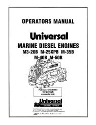
OPERATORS MANUAL - Westerbeke
OPERATORS MANUAL - Westerbeke
OPERATORS MANUAL - Westerbeke

You also want an ePaper? Increase the reach of your titles
YUMPU automatically turns print PDFs into web optimized ePapers that Google loves.
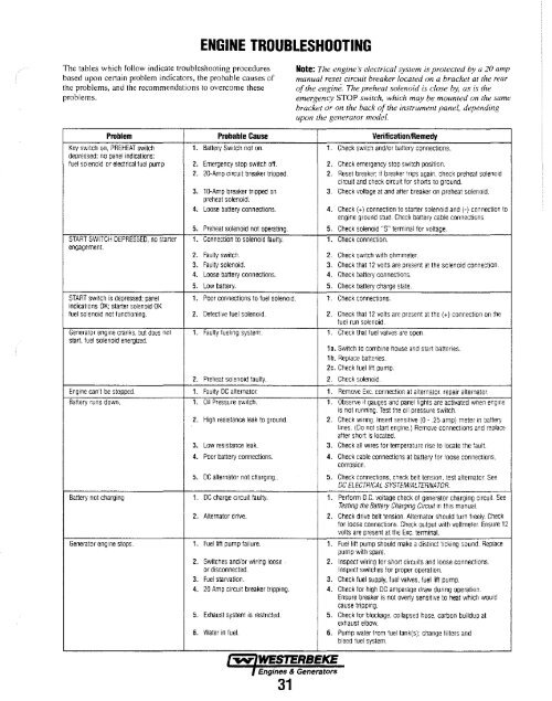
The tables which follow indicate troubleshooting procedures<br />
based upon certain problem indicators, the probable causes of<br />
the problems, and the recommendations to overcome these<br />
problems.<br />
Problem Probable Cause<br />
ENGINE TROUBLESHOOTING<br />
Key switch on, PREHEAT switch 1. Battery Switch not on.<br />
depressed: no panel indications:<br />
fuel solenoid or electrical fuel pump 2. Emergency stop sw"itch off.<br />
2. 20-Amp circuit breaker tripped.<br />
START SWITCH DEPRESSED, no starter<br />
engagement.<br />
3. 1 a-Amp breaker tripped on<br />
preheat solenoid.<br />
4. Loose battery connections.<br />
,<br />
5. Preheat solenoid not operating.<br />
. Connection to solenoid faulty.<br />
2. Faulty switch.<br />
3. Faulty solenoid.<br />
4. Loose battery connections.<br />
5. Low battery.<br />
START switch is depressed: panel 1. Poor connections to fuel solenOid.<br />
indications OK; starter solenoid OK<br />
fuel solenoid not functioning. 2. Defective fuel solenoid.<br />
Generator engine cranks, but does not 1. Faulty fueling system.<br />
start, fuel solenoid energized.<br />
2. Preheat solenoid faulty.<br />
Engine can't be stopped. 1. Faulty DC alternator.<br />
Battery funs down. 1. Oil Pressure switch.<br />
2. High resistance leak to ground.<br />
3. Low resistance leak.<br />
4. Poor battery connections.<br />
5. DC alternator not charging ..<br />
Battery not charging 1. DC charge circuit faulty.<br />
2. Alternator drive.<br />
Generator eogme stops. 1. Fuel lift pump failure.<br />
2. Switches and/or wiring loose·<br />
or disconnected.<br />
3. Fuel starvation.<br />
4. 20 Amp circuit breaker tripping.<br />
5. Exhaust system is restricted.<br />
6. Water in fuel.<br />
Note: The engine s electrical system is protected by a 20 amp<br />
manual reset circuit breaker located on a bracket at the rear<br />
of the engine. The preheat solenoid is close by, as is the<br />
emergency STOP switch, which may be mounted on the same<br />
bracket or on the back of the instrument panel, depending<br />
upon [he generator model.<br />
Verification/Remedy<br />
1. Check switch and/or battery connections.<br />
2. Check emergency stop SW'ltch posItion.<br />
2. Reset breaker; if breaker trips again, check preheat solenoid<br />
circuit and check circuit for shorts to ground.<br />
3. Check voltage at and after breaker on preheat solenoid.<br />
4. Check (+) connection to starter solenoid and (-) connection to<br />
engine grouna stud. Check battery cable connections<br />
5. Check solenoid "S" terminal for voltage,<br />
1. Check connection.<br />
2. Check switch with ohmmeter.<br />
3. Check that 12 volts are present at the solenoid connection.<br />
4. Check battery connections.<br />
5. Check battery charge stale.<br />
1. Check connections.<br />
2. Check thaI 12 volts are present at the (+) connection on the<br />
fuel fun solenoid.<br />
. Check that fuel valves are open,<br />
,<br />
, "¥I17,WESTERBEKE<br />
I Engines & Generators<br />
31<br />
1a. Switch 10 combme house and start batteries.<br />
1 b. Replace batteries.<br />
2e. Check fuel lift pump.<br />
2. Check solenoid.<br />
1. Remove Exc. connection at alternator, repair alternator.<br />
1. Observe if gauges and panel lights are activated when engme<br />
is not running. Test the 011 pressure switch.<br />
2. Check wiring. Insert sensitive (0 - .25 amp) meter in battery<br />
lines. (Do not start engine.) Remove connections and replace<br />
after short is located.<br />
3. Check all wires for temperature rise to locate the fault.<br />
4. Check cable connections at battery for loose connections,<br />
corrosion.<br />
5. Check connections, check belt tension. test alternator. See<br />
DC ELECTRICAL SYSTEM/ALTERNATOR<br />
1. Perform D.C. voltage check of generator charging Clfcuit. See<br />
Testing the Battery Charging Circuit in this manual.<br />
2. Check drive belt tension. Alternator should turn freely. CheCk<br />
for loose connections. Check output with voltmeter. Ensure 12<br />
volts are present at the Exc. terminal.<br />
1. Fuel lift pump should make a distinct ticking sound. Replace<br />
pump with spare.<br />
2. Inspect wiring for short circuits and loose connections.<br />
Inspect switches for proper operation.<br />
3. Check fuel supply, fuel valves. fuel lift pump.<br />
4. Check for high DC amperage draw during operation.<br />
Ensure breaker is not overly sensitive to heat which would<br />
cause tripping.<br />
5. Check for blockage, collapsed hose, carbon buildup at<br />
exhaust elbow.<br />
6. Pump water from fuel tank(s); change filters and<br />
bleed fuel system.