AutoScan Spectrophotometer Instrument Operator's Manual - X-Rite
AutoScan Spectrophotometer Instrument Operator's Manual - X-Rite
AutoScan Spectrophotometer Instrument Operator's Manual - X-Rite

Create successful ePaper yourself
Turn your PDF publications into a flip-book with our unique Google optimized e-Paper software.
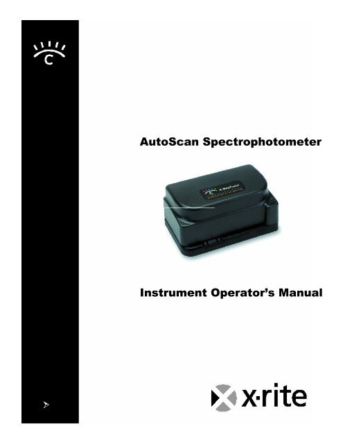
<strong>AutoScan</strong> <strong>Spectrophotometer</strong><br />
<strong>Instrument</strong> Operator’s <strong>Manual</strong>
Electronic Emission Notices<br />
Federal Communications Commission Notice<br />
NOTE: This equipment has been tested and found to comply with the limits for a Class A digital device, pursuant to part 15 of the FCC<br />
rules. These limits are designed to provide reasonable protection against harmful interference in a residential installation. This<br />
equipment generates, uses and can radiate radio frequency energy and, if not installed and used in accordance with the instructions, may<br />
cause harmful interference to radio communications. However, there is no guarantee that interference will not occur in a particular<br />
installation. If this equipment does cause harmful interference to radio or television reception, which can be determined by turning the<br />
equipment off and on, the user is encouraged to try to correct the interference by one or more of the following measures:<br />
Reorient or relocate the receiving antenna.<br />
Increase the separation between the equipment and receiver.<br />
Connect the equipment into an outlet on a circuit different from that to which the receiver is connected.<br />
Consult the dealer or service representative for help.<br />
Industry Canada Compliance Statement<br />
This digital apparatus does not exceed the Class A limits for radio noise emissions from digital apparatus as set out in the interferencecausing<br />
equipment standard entitled: “Digital Apparatus”, ICES-003 of Industry Canada.<br />
Avis de conformité aux normes d’Indstrie Canada<br />
Cet appareil numérique respecte les limites de bruits radioélectriques applicables aux appareils numériques de Classe A prescrites dans<br />
la norme sur le matériel brouilleur : “Appareils numériques”, NMB-003 édictée par Industrie Canada.<br />
NOTE: Shielded interface cables must be used in order to maintain compliance with the desired FCC and European<br />
emission requirements.<br />
For 115V~/230V~: Use only SE30-77 AC Adapter.<br />
Für 115V~/230V~: verwenden Sie nur das X-<strong>Rite</strong> Netzteil P/N SE30-77.<br />
Para 115V~/230~: Use solamente el adaptador C.A. de X-<strong>Rite</strong>, pieza SE30-77.<br />
Pour 115V~/230~: Utiliser seulement l’adaptateur AC de X-<strong>Rite</strong> P/N SE30-77.<br />
Per 115V~/230~: Usare solamente il adattatore C.A. al X-<strong>Rite</strong>, pezzo SE30-77.<br />
The Manufacturer: X-<strong>Rite</strong>, Incorporated<br />
Der Hersteller: 4300 44th Street, S.E.<br />
El fabricante: Grand Rapids, Michigan 49512<br />
Le fabricant:<br />
Il fabbricante:<br />
Declares that: <strong>Spectrophotometer</strong><br />
gibt bekannt: DTP41<br />
advierte que:<br />
avertit que:<br />
avverte che:<br />
is not intended to be connected to a public telecommunications network.<br />
an ein öffentliches Telekommunikations-Netzwerk nicht angeschlossen werden soll.<br />
no debe ser conectado a redes de telecomunicaciones públicas.<br />
ne doit pas être relié à un réseau de télécommunications publique.<br />
non deve essere connettuto a reti di telecomunicazioni pubblici.
CE Declaration<br />
Manufacturer's Name: X-<strong>Rite</strong>, Incorporated<br />
Manufacturer's Address: 4300 44 th Street, S.E.<br />
Grand Rapids, Michigan 49512<br />
U.S.A.<br />
Model Name: <strong>Spectrophotometer</strong><br />
Model No.: DTP41 Series<br />
Directive(s) Conformance: EMC 89/336/EEC LVD 73/23/EEC<br />
WEEE<br />
As of August 13, 2005, X-<strong>Rite</strong> products meet the European Union – Waste Electrical and Electronic Equipment<br />
(WEEE) directive. Please refer to www.xrite.com for more information on X-<strong>Rite</strong>’s compliance with the<br />
WEEE directive.<br />
Table of Contents<br />
1 Overview and Setup...............................................................................................................................1<br />
<strong>Instrument</strong> Description ..............................................................................................................................1<br />
Unpacking and Inspection.........................................................................................................................1<br />
Packaging Content............................................................................................................................................. 1<br />
<strong>Instrument</strong> Interface ..................................................................................................................................2<br />
USB Driver Installation (Windows Only) ............................................................................................................ 2<br />
<strong>Instrument</strong> LED Indicator ..........................................................................................................................3<br />
Operation Mode (Green Light) ........................................................................................................................... 3<br />
Calibration Mode (Yellow Light) ......................................................................................................................... 3<br />
Error/Reset Mode (Red Light)............................................................................................................................ 3<br />
Changing the Position of the Backing Block .............................................................................................3<br />
2 Calibration and Measurement............................................................................................................4<br />
Frequency of Calibration...........................................................................................................................4<br />
Reflection Mode Calibration......................................................................................................................4<br />
Transmission Mode (Black) Calibration ....................................................................................................4<br />
Strip Positioning and Measurement Techniques ......................................................................................5<br />
3 General Maintenance ...................................................................................................................................6<br />
Repair Information ....................................................................................................................................6<br />
Cleaning the <strong>Instrument</strong>............................................................................................................................6<br />
General Cleaning ............................................................................................................................................... 6<br />
Cleaning the Strip Reading Mechanism............................................................................................................. 6<br />
Cleaning the Reference Strip....................................................................................................................7<br />
4 Appendices................................................................................................................................................8<br />
Technical Support .....................................................................................................................................8<br />
<strong>Instrument</strong> Specifications..........................................................................................................................8
Proprietary Notice<br />
The information contained in this manual is derived from patent and proprietary data of X-<strong>Rite</strong>, Incorporated. Publication of this<br />
information does not imply any rights to reproduce or use this manual for purposes other than installing, operating, or maintaining this<br />
instrument and software. No part of this manual may be reproduced, transcribed, transmitted, stored in a retrieval system, or translated<br />
into any language or computer language, in any form or by any means, electronic, magnetic, mechanical, optical, manual, or<br />
otherwise, without the prior written permission of an officer of X-<strong>Rite</strong>, Incorporated.<br />
These provisions are intended to state all of the rights and responsibilities between X-<strong>Rite</strong>, Incorporated and the customer. They<br />
supersede all warranties, expressed or implied, and whether of merchantability, fitness or otherwise. The remedies contained in this<br />
manual are exclusive. Customer and X-<strong>Rite</strong>, Incorporated waive all other remedies, including but not limited to consequential<br />
damages. This instrument may be covered by one or more patents. Refer to the instrument for actual patent numbers.<br />
Copyright © 2007 by X-<strong>Rite</strong>, Incorporated “ALL RIGHTS RESERVED”<br />
X-<strong>Rite</strong>, X-<strong>Rite</strong>Color, and the X-<strong>Rite</strong> Color Logo are registered trademarks of X-<strong>Rite</strong>, Incorporated. Windows is a registered trademark of Microsoft Corporation. Power Mac is a trademark of Apple Computer, Inc., registered<br />
in the United States and other countries. All other logos, brand names, and product names are the properties of their respective holders.<br />
Warranty Information<br />
X-<strong>Rite</strong>, Incorporated (“X-<strong>Rite</strong>”) warrants each instrument manufactured to be free of defects in material and workmanship (excluding<br />
battery pack) for a period of 12 months. This warranty shall be fulfilled by the repair or replacement, at the option of X-<strong>Rite</strong>, of any<br />
part or parts, free of charge including labor, F.O.B. its factory or authorized service center.<br />
This warranty shall be voided by any repair, alteration, or modification, by persons other than employees of X-<strong>Rite</strong>, or those expressly<br />
authorized by X-<strong>Rite</strong> to perform repairs, and by any abuse, misuse, or neglect of the product, or by use not in accordance with X-<br />
<strong>Rite</strong>’s published instructions.<br />
X-<strong>Rite</strong> reserves the right to make changes in design and /or improvements to its products without any obligation to include these<br />
changes in any products previously manufactured. Correction of defects by repair or replacement shall constitute fulfillment of all<br />
warranty obligations on the part of X-<strong>Rite</strong>.<br />
THIS WARRANTY IS EXPLICITLY IN LIEU OF ANY OTHER EXPRESSED OR IMPLIED WARRANTIES, INCLUDING<br />
ANY IMPLIED WARRANTY OF MERCHANTABILITY OR FITNESS FOR ANY PARTICULAR PURPOSE. THIS<br />
WARRANTY OBLIGATION IS LIMITED TO REPAIR OR REPLACEMENT OF THE UNIT RETURNED TO X-RITE OR AN<br />
AUTHORIZED SERVICE CENTER FOR THAT PURPOSE.<br />
This agreement shall be interpreted in accordance with the laws of the State of Michigan and jurisdiction and venue shall lie with the<br />
courts of Michigan as selected by X-<strong>Rite</strong>, Incorporated.
1 Overview and Setup<br />
INSTRUMENT DESCRIPTION<br />
The X-<strong>Rite</strong>Color ® <strong>AutoScan</strong> <strong>Spectrophotometer</strong> is a 24-band color measurement instrument that reports densitometric,<br />
colorimetric, and spectral data. The instrument is primarily interfaced with Raster Image Processors (RIPs), Color Copiers,<br />
and Color Printers and Proofers utilizing third party color management software control. The instrument is open ended on<br />
the left side to read linear groups of patches on large media sheets without cutting.<br />
Your instrument package includes separate software utilities for Macintosh and Windows operating systems, and a<br />
calibration reference for quick calibration of the instrument. This manual covers the installation, calibration, and<br />
maintenance of the X-<strong>Rite</strong>Color <strong>AutoScan</strong> <strong>Spectrophotometer</strong>. Specific instructions for using the instrument with your<br />
third-party software program can be found in the third-party software documentation.<br />
Alignment Mark<br />
Shipping Spacer (remove)<br />
Strip Entrance<br />
UNPACKING AND INSPECTION<br />
<strong>Instrument</strong> Button (Start/Cancel/Calibrate)<br />
Three Color LED Indicator<br />
Interface Cable Connection<br />
After removing the instrument from the shipping carton, inspect it for damage. If any damage has occurred during<br />
shipping, immediately contact the transportation company. Do not proceed with installation until the carrier’s agent has<br />
inspected the damage.<br />
Your instrument was packaged in a specially designed carton to assure against damage. If shipment is necessary, the<br />
instrument should be packaged in the original carton. If the original carton is not available, contact X-<strong>Rite</strong> to have a<br />
replacement shipped to you.<br />
Packaging Content<br />
Your instrument packaging should contain all the items listed below. If any of these items are missing, contact X-<strong>Rite</strong> or<br />
an Authorized Representative.<br />
• DTP41 <strong>Instrument</strong><br />
• Interface Cable<br />
• Power Supply<br />
• Calibration Reference<br />
• Certificate of Calibration<br />
• Documentation, Utility CD and Registration Materials<br />
NOTE: DEPENDING ON THE CONFIGURATION, YOUR INSTRUMENT MAY NOT BE AVAILABLE<br />
WITH ALL THE OPTIONS SHOWN.<br />
1
X-<strong>Rite</strong>Color <strong>AutoScan</strong> <strong>Spectrophotometer</strong><br />
2<br />
INSTRUMENT INTERFACE<br />
The instrument must be interfaced directly with one of the computer’s Serial or USB ports. For attachment to a Mac Mini-<br />
DIN 8 Serial Port, you need to use the optional adapter (P/N SE108-DB9PA-01).<br />
1. Quit all programs and shut down the computer before installing interface cabling.<br />
2. Connect appropriate interface cables as shown.<br />
CAUTION: Use only the Switching Power Supply (SE30-77) to power the instrument.<br />
Locking<br />
Connector<br />
Operation<br />
3. Plug the small end of the switching power supply into the power input connector of the interface cable.<br />
4. Plug the detachable line cord into the power supply and then into the AC wall receptacle. The instrument does<br />
not have an ON/OFF switch.<br />
Grasp and push the<br />
connector at this<br />
location to insert.<br />
SE108-USBSERDB9<br />
(Optional)<br />
Grasp and pull the<br />
connector at this<br />
location to remove.<br />
SE108-DB9PA-01<br />
(Optional)<br />
USB<br />
SE30-77 Switching<br />
Power Supply<br />
Detachable Line Cord<br />
AC Wall<br />
Receptacle<br />
Power Input<br />
SE108-96-02 *<br />
Interface Cable<br />
USB Driver Installation (Windows Only)<br />
A USB driver must be installed in the computer to allow the instrument to work with your software application if the USB<br />
interface cable is used. Follow the steps below to install the required USB driver.<br />
1. Make sure the switching power supply is plugged into the instrument and the computer in on.<br />
2. After the USB cable is plugged into your computer, you must install the USB driver that came with your instrument.<br />
3. The USB driver is located in the Driver folder on the <strong>Manual</strong>s and Utilities CD.<br />
* May not be included in all models.<br />
USB<br />
PC<br />
DB9<br />
SE108-97-02 *<br />
Interface Cable<br />
MAC<br />
Mini-DIN 8
INSTRUMENT LED INDICATOR<br />
Overview and Setup<br />
The LED indicates a variety of instrument operation conditions, such as calibration mode, and operation. Below is a<br />
complete list of all conditions reported by the LED.<br />
Operation Mode (Green Light)<br />
• Solid Green Light—self test passed and instrument is ready for use with defined strip.<br />
• Slow Flashing Green Light—strip reading in progress (strip being read).<br />
• Fast Flashing Green Light—strip reading attempted but the wrong strip was inserted, or strip skewed during reading.<br />
Calibration Mode (Yellow Light)<br />
• Solid Yellow Light—instrument calibration was entered, ready to start calibration with next button press.<br />
• Slow Flashing Yellow Light—instrument calibration in progress (strip being read).<br />
• Solid Green Light after Yellow Light—instrument calibration was successful and instrument is ready for use.<br />
• Fast Flashing Yellow Light—instrument calibration failed, re-read calibration strip. If error persists, clean instrument<br />
and calibration strip (see Section Three). If error still persists, contact your Service Representative.<br />
Error/Reset Mode (Red Light)<br />
• Solid Red Light—and error was detected, the self test failed. Verify correct power supply is used. Turn power off,<br />
reapply power and see if condition is corrected; if not, contact Service Representative.<br />
• Solid Green or Yellow changing to Red—an instrument reset is in progress. To initiate a reset, press and hold the<br />
button, the LED changes from Green or Yellow to Red. While the LED is Red, press button again (within 10<br />
seconds). The LED changes to Green and the reset is performed, reinstating the factory defaults. If the second button<br />
press is not performed when the LED is Red, the instrument will time-out, causing the LED to change to Green and<br />
the reset to be aborted.<br />
CHANGING THE POSITION OF THE BACKING BLOCK<br />
NOTE: <strong>Instrument</strong>s that utilize a “raised white backing block” cannot be repositioned.<br />
The backing surface used when measuring paper strips can be alternated between ANSI Black and White Diffusing Opal.<br />
The Backing Block is located on the bottom of the Base Assembly. Simply slide the block to the “right” for Black or to<br />
the “left” for White (see below). The factory setting for reflection instruments is Black backing. For transmission<br />
instruments (DTP41/T), the optics block must remain in the “T/W” position (left) to measure film strips. The block<br />
can be slid to the “BL” position (right) for measuring paper strips with a black backing if desired.<br />
Reflection <strong>Instrument</strong><br />
Slide block to the left for White<br />
Diffusing Opal backing<br />
“T/W” is visible with<br />
White Opal<br />
Transmission <strong>Instrument</strong><br />
The optics block must be slid to the “T/W”<br />
position (transmission) when measuring film<br />
strips. A small screwdriver can be used to slide<br />
the optics block from one position to the other.<br />
“BL” is visible with Black<br />
Slide block to the right for<br />
ANSI Black backing<br />
Reflection Only<br />
Slot for sliding block to the right<br />
(ANSI Black backing)<br />
Slot for sliding block to the<br />
left (default position)<br />
3
4<br />
2 Calibration and Measurement<br />
FREQUENCY OF CALIBRATION<br />
Typically, the host computer prompts for an instrument calibration when required. The frequency at which this occurs<br />
depends on the application. If desired, a reflection calibration can be invoked manually by pressing the <strong>Instrument</strong><br />
button—refer below for procedure. At a minimum the instrument should be calibrated once a day for best accuracy.<br />
REFLECTION MODE CALIBRATION<br />
The X-<strong>Rite</strong>Color <strong>AutoScan</strong> <strong>Spectrophotometer</strong> has a unique automatic calibration feature. When the instrument performs a<br />
calibration procedure, the Color Reflection Reference is automatically scanned, simplifying the procedure. The instrument<br />
employs a number of self-checking procedures to verify calibration accuracy during normal use. When internal limits are<br />
exceeded, the computer calls for a calibration.<br />
CALIBRATION NOTE:<br />
Handle Color Reflection Reference by the edges. Make sure<br />
that the Color Reflection Reference is free of dust, dirt, and<br />
smudgemarks. Refer to Section Three for cleaning procedure.<br />
Always store the Color Reflection Reference in its protective<br />
envelope away from light and heat.<br />
1. Center the designated end of the Color Reflection<br />
Reference under the alignment mark. Slowly insert strip<br />
past the front idler rollers up to the black bar on the<br />
reference strip.<br />
2. To manually force the instrument into calibration mode,<br />
press and hold the <strong>Instrument</strong> button for a minimum of three<br />
seconds. The indicator light changes to yellow. Note, if calibration is<br />
not performed after a short period of time, the instrument returns to<br />
the measurement mode (green light).<br />
3. Press the <strong>Instrument</strong> button again. The light slowly flashes yellow.<br />
After a few moments, the light changes to green and then back to<br />
slow flashing yellow. The strip is then pulled through the instrument<br />
and out the back. The light turns solid green after a successful<br />
calibration. If the calibration fails (fast flashing yellow light), verify<br />
strip is clean and re-read.<br />
4. Place Color Reflection Reference in its protective envelope.<br />
NOTE: The optics block must remain in the T/W position when<br />
calibrating a DTP41/T instrument.<br />
Press button<br />
down for 3 sec. to<br />
initiate calibration,<br />
then press button<br />
again<br />
Slowly insert strip up<br />
to the black bar<br />
TRANSMISSION MODE (BLACK) CALIBRATION<br />
NOTE: Transmission operation is optional. Therefore, transmission mode calibration may not be available on your<br />
instrument.<br />
A transmission calibration is recommended for the DTP41/T instrument approximately once a week for optimal<br />
performance. The host computer initiates the procedure and prompts you to insert the calibration envelope (transmission<br />
calibration cannot be initiated manually). This procedure guides you through the mechanical aspects of positioning the<br />
envelope in the instrument.<br />
1. When the host computer indicates a transmission calibration is needed, center the designated end of the Color<br />
Reflection Reference Envelope under the alignment mark. Slowly insert past the front idler rollers until it comes to<br />
rest against the rear drive rollers (approx. three inches).<br />
2. Activate the cal procedure at the computer. NOTE: This is a static measurement, the envelope is not pulled through<br />
the instrument.<br />
• The instrument beeps once, flashes yellow slowly and takes a series of five measurements. After completion, the<br />
instrument beeps again and the indicator light changes to solid green.<br />
3. Remove the Color Reflection Reference Envelope from the <strong>Instrument</strong>.
Alignment mark<br />
Slowly insert envelope until it<br />
stops against the drive rollers<br />
STRIP POSITIONING AND MEASUREMENT TECHNIQUES<br />
Calibration and Measurement<br />
You should refer to the documentation for the software program that you are using with your instrument. All applications<br />
that utilize the instrument will require that you have the software running during strip measurements. The following<br />
information is provided to familiarize you with the “mechanical” requirements of guiding a strip through the instrument.<br />
MEASUREMENT NOTE:<br />
The strip must have a 1.5” (38.10mm) leader before the leading edge of the first step (contact X-<strong>Rite</strong> Applications Support<br />
if additional information is required). Inspect the strip for spots or defects on the step. Defects may cause inaccurate<br />
measurements. Position the strip so that the group of patches to measure is directly under alignment mark on the cover.<br />
Insert the leading edge of the strip past the front idler rollers until it stops against the rear drive rollers (approximately three<br />
inches). Press the <strong>Instrument</strong> button, the motor activates and automatically pulls the strip through the instrument. For large<br />
strips (media that extends outside the left side of the cover), guide the strip with slight pressure. This prevents skewing of<br />
the strip as it is measured. Do not “tug” forwards or backwards on strip while internal motor is pulling strip through.<br />
1. Select strip type to measure from software.<br />
2. If required, initiate reading by pressing <strong>Instrument</strong> button. LED indicator should flash green slowly during reading.<br />
3. Position the strip so that the patches to measure are directly under alignment mark. Insert the strip past the front idler<br />
rollers until it stops against the rear drive rollers. Press the <strong>Instrument</strong> button to activate reading.<br />
4. Verify that the strip was read successfully by viewing the computer monitor. If an error message is noted, try remeasuring<br />
strip.<br />
Insert strip until it stops against the rear drive<br />
rollers and press <strong>Instrument</strong> button<br />
When measuring large strips, guide<br />
along outside edge<br />
5
6<br />
3 General Maintenance<br />
REPAIR INFORMATION<br />
The X-<strong>Rite</strong>Color <strong>AutoScan</strong> <strong>Spectrophotometer</strong> is covered by a one-year limited warranty and should be referred to the<br />
factory or an authorized service center for repairs within the warranty period.<br />
X-<strong>Rite</strong> provides a factory repair service to their customers. Because of the complexity of the circuitry, all repairs<br />
should be referred to the factory or an authorized service center.<br />
X-<strong>Rite</strong> will repair any instrument past warranty. The customer shall pay shipping and repair cost to the factory or<br />
authorized service center, and the instrument shall be submitted in the original carton, as a complete unaltered unit.<br />
CLEANING THE INSTRUMENT<br />
Your instrument requires very little maintenance to achieve years of reliable operation. However, to protect your<br />
investment and maintain reading accuracy, a few simple-cleaning procedures should be performed from time to time.<br />
General Cleaning<br />
Whenever required, the exterior of the instrument may be wiped clean with a cloth dampened in water or mild cleaner.<br />
NOTE: DO NOT use any solvents to clean the unit, this will cause damage to the cover.<br />
Cleaning the Strip Reading Mechanism<br />
The reading mechanism should be cleaned once a week in normal environments, and more often in dirty or dusty<br />
environments.<br />
1. Turn instrument upside-down.<br />
2. Using your index finger and thumb, pinch the two tabs on the bottom of the base assembly towards each other.<br />
3. Holding the tabs, lift base assembly upward.<br />
Base Tabs<br />
Base Assembly
4. Clean base surface, bottom plate surface, idler rollers, and drive wheels with a lint-free cloth.<br />
General Maintenance<br />
NOTE: To thoroughly clean the entire drive wheel, press the <strong>Instrument</strong> button—with instrument plugged in—to rotate<br />
wheels. DO NOT press button with instrument setting flat on Bottom Plate Surface, drive wheels may move instrument.<br />
Idler Rollers<br />
Idler Rollers<br />
Drive Wheels<br />
Bottom Plate<br />
Surface<br />
Base Surface<br />
Idler Rollers<br />
5. Position Base Assembly over Bottom Plate and insert tabs into openings. The Base is positioned properly when it<br />
snaps into place. When reassembling a transmission unit (DTP41/T), make sure the optics connector is properly<br />
seated before snapping into place.<br />
CLEANING THE REFERENCE STRIP<br />
The calibration reference strip can be cleaned with a lint free cloth whenever required. Make sure to return reference<br />
strip to its protective case when finished.<br />
If required, a new reference strip can be ordered from X-<strong>Rite</strong>, Part Number DTP41-100-KIT.<br />
Always handle reference strip by the edges.<br />
Serial Number Label<br />
7
8<br />
4 Appendices<br />
TECHNICAL SUPPORT<br />
The <strong>AutoScan</strong> <strong>Spectrophotometer</strong> is used with a number of third party software vendors. To get the most specialized<br />
technical assistance, you should first contact the technical service representative for the specific third-party software<br />
that you are using.<br />
Before contacting X-<strong>Rite</strong> with a potential instrument problem, you should perform a complete instrument reset. This<br />
reset will reinitialize the instrument’s firmware and reinstate the factory default settings. To perform reset, unplug the<br />
instrument’s power. Press and hold the instrument button and plug-in power. Release button after LED starts to flash<br />
red (approx. 3 seconds).<br />
If you are still having a problem after performing a reset, contact X-<strong>Rite</strong> Customer Service toll-free by phone at:<br />
1-888-826-3059; or by fax at: 1-888-826-3061.<br />
Our Customer Service Department is fully staffed with qualified technicians to assist you via phone or fax. When<br />
placing a call, please have the following information close at hand:<br />
Your instrument serial number (located on the Bottom Plate, see Cleaning the Strip Reading Mechanism for<br />
location) and calibration reference serial number<br />
Your utility software version number<br />
Your name and company name<br />
Your telephone number<br />
Write down any error messages and what prompted them<br />
Have the hardware and software running within reach of the telephone<br />
INSTRUMENT SPECIFICATIONS<br />
Measurement Geometry: 45°/0° per ANSI/ISO 5-4 (IT2.17) (Reflection)<br />
180°/0° per ANSI/ISO 5-2 (IT2.19) (Transmission)<br />
Spot Size at Sample: 1.8mm (.070 in) in scan direction, 2.5mm (.097 in) wide<br />
Light Source: Gas Pressure @ 2850 °K<br />
Spectral Sensor: DRS Technology, 24 point engine, 31 point reporting<br />
Spectral Range: 400nm to 700nm<br />
Illuminant Types: A, C, D50, D55, D65, D75, F2, F7, F11, & F12<br />
Standard Observers: 2° & 10°<br />
Response Type: Status T, E, I, A, M, & Others<br />
Measurement Time: Approx. 0.25 seconds per patch (7mm patches)<br />
Reflection Measurement (DTP41 & DTP41/T)<br />
Inter-instrument Agreement: 0.3 ΔE cmc avg typical (avg, based on 12 BCRA tiles)<br />
Measurement Range: 0.00D to 2.50 D; 0 to 160% R<br />
Repeatability on White: 0.2 ΔE max; ±0.01D max<br />
Linearity: +/- .01D or 1%<br />
Transmission Measurement (DTP41/T)<br />
Inter-instrument Agreement: 0.02D or 2% typical, 0 to 3.0 D<br />
Measurement Range: 0.00D to 5.00 D; 0 to 110% T<br />
Repeatability: ±0.01D or 1% 0 to 3.5 D (Visual)<br />
Calibration: Calibration strip for Reflection<br />
Environmental: +10 (50 F) to +40 °C (104 F) operating,<br />
30% to 85% RH non condensing<br />
Warm Up time: None<br />
Power Required: 12v DC, Universal 100-240VAC Adapter; 50/60Hz<br />
Dimensions: Height: 88mm (3.45 in); Width: 184mm (7.25 in); Depth: 114mm (4.5 in)<br />
Weight: 890g (1.96 lb) , with /T option 1090g (2.40 lb)<br />
These specifications are subject to change without notice.
Corporate Headquarters - USA<br />
4300 44th Street SE<br />
Grand Rapids, Michigan 49512<br />
Phone 1 800 248 9748 or 1 616 803 2100<br />
Fax 1 800 292 4437 or 1 616 803 2705<br />
Corporate Headquarters - Europe<br />
Althardstrasse 70<br />
8105 Regensdorf<br />
Switzerland<br />
Phone (+41) 44 842 24 00<br />
Fax (+41) 44 842 22 22<br />
Corporate Headquarters - Asia<br />
Room 808-810<br />
Kornhill Metro Tower, 1 Kornhill Road<br />
Quarry Bay, Hong Kong<br />
Phone (+852) 2 568 6283<br />
Fax (+852) 2 885 8610<br />
Please visit www.xrite.com for a local office near you.<br />
P/N DTP41-500 Rev. O