PDT 6800 Series Product Reference Guide
PDT 6800 Series Product Reference Guide
PDT 6800 Series Product Reference Guide

Create successful ePaper yourself
Turn your PDF publications into a flip-book with our unique Google optimized e-Paper software.
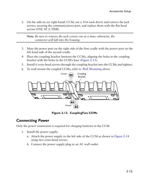
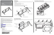
Accessories Setup<br />
2. On the add-on (or right-hand) CCM, use a 3/16-inch driver and remove the jack<br />
screws, securing the communications port, and replace them with the flat-head<br />
screws ONE AT A TIME.<br />
Note: Be sure to remove the jack screws one at a time; otherwise, the<br />
connector will fall into the housing.<br />
3. Mate the power port on the right side of the first cradle with the power port on the<br />
left hand side of the second cradle.<br />
4. Place the coupling bracket between the CCMs, aligning the holes in the coupling<br />
bracket with the holes in the CCM’s base (Figure 2-13).<br />
5. Install 6 cross-head screws through the coupling bracket into the CCMs and tighten.<br />
6. To wall mount the coupled CCMs, refer to Wall Mounting above.<br />
Connecting Power<br />
Screws Coupling<br />
Bracket<br />
Screws<br />
Figure 2-13. Coupling Two CCMs<br />
Only the power connection is required for charging batteries in the CCM.<br />
1. Install the power supply.<br />
a. Attach the power supply to the left side of the CCM as shown in Figure 2-14<br />
using two cross-head screws.<br />
b. Connect the power supply plug to an AC wall outlet.<br />
2-13


![MC55 Regulatory Guide [Spanish] (P/N 72-108860 ... - Enterprise](https://img.yumpu.com/14574395/1/190x133/mc55-regulatory-guide-spanish-p-n-72-108860-enterprise.jpg?quality=85)
![ES400 Regulatory Guide [Spanish] (P/N 72-134312-01ES Rev. A)](https://img.yumpu.com/14415156/1/190x127/es400-regulatory-guide-spanish-p-n-72-134312-01es-rev-a.jpg?quality=85)
![MC35 Regulatory Information [Spanish] - Symbol](https://img.yumpu.com/14415086/1/190x143/mc35-regulatory-information-spanish-symbol.jpg?quality=85)