

DGC Brushless Excitation - Emerson Process Management
DGC Brushless Excitation - Emerson Process Management
DGC Brushless Excitation - Emerson Process Management

You also want an ePaper? Increase the reach of your titles
YUMPU automatically turns print PDFs into web optimized ePapers that Google loves.
<strong>DGC</strong> <strong>Brushless</strong> <strong>Excitation</strong><br />
System Description<br />
For WTA retrofits, the Integrated Power Amplifier incorporates the functionality of the Firing and<br />
Power drawers into one drawer. The Firing Drawers are removed and discarded and the Power<br />
Amplifiers are replaced with new Integrated Power Amplifiers. The Integrated Power Amplifier has<br />
the same form and fit as the existing WTA<br />
Power Drawer, utilizing the existing racking<br />
mechanism and bus-bar connections in the rear.<br />
A new cable and connector arrangement is<br />
installed to support the other needed<br />
connections.<br />
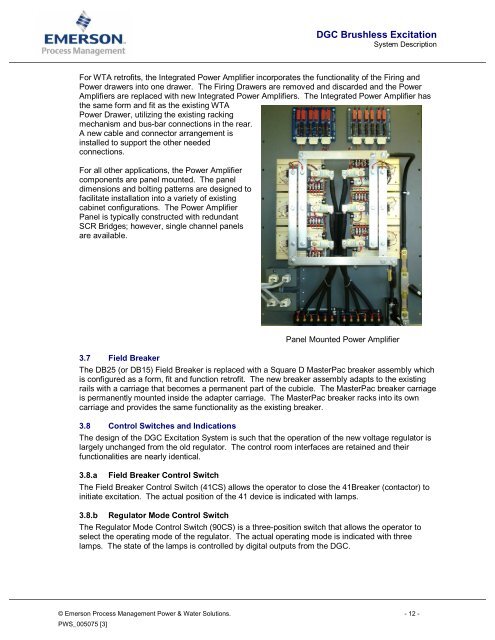
For all other applications, the Power Amplifier<br />
components are panel mounted. The panel<br />
dimensions and bolting patterns are designed to<br />
facilitate installation into a variety of existing<br />
cabinet configurations. The Power Amplifier<br />
Panel is typically constructed with redundant<br />
SCR Bridges; however, single channel panels<br />
are available.<br />
Panel Mounted Power Amplifier<br />
3.7 Field Breaker<br />
The DB25 (or DB15) Field Breaker is replaced with a Square D MasterPac breaker assembly which<br />
is configured as a form, fit and function retrofit. The new breaker assembly adapts to the existing<br />
rails with a carriage that becomes a permanent part of the cubicle. The MasterPac breaker carriage<br />
is permanently mounted inside the adapter carriage. The MasterPac breaker racks into its own<br />
carriage and provides the same functionality as the existing breaker.<br />
3.8 Control Switches and Indications<br />
The design of the <strong>DGC</strong> <strong>Excitation</strong> System is such that the operation of the new voltage regulator is<br />
largely unchanged from the old regulator. The control room interfaces are retained and their<br />
functionalities are nearly identical.<br />
3.8.a Field Breaker Control Switch<br />
The Field Breaker Control Switch (41CS) allows the operator to close the 41Breaker (contactor) to<br />
initiate excitation. The actual position of the 41 device is indicated with lamps.<br />
3.8.b Regulator Mode Control Switch<br />
The Regulator Mode Control Switch (90CS) is a three-position switch that allows the operator to<br />
select the operating mode of the regulator. The actual operating mode is indicated with three<br />
lamps. The state of the lamps is controlled by digital outputs from the <strong>DGC</strong>.<br />
© <strong>Emerson</strong> <strong>Process</strong> <strong>Management</strong> Power & Water Solutions. - 12 -<br />
PWS_005075 [3]


