REV-i - P8ntbox
REV-i - P8ntbox
REV-i - P8ntbox

Create successful ePaper yourself
Turn your PDF publications into a flip-book with our unique Google optimized e-Paper software.
O W N E R ’ S M A N U A L<br />
W W W . d A N g E R O U S p O W E R . c O M
A WORd FROM OUR ENgiNEERS ANd dESigN tEAM<br />
Our challenge was tO blend the art Of metal sculpture with masterful<br />
electrOnics in a package that symbOlizes strength, pOwer, and dexterity.<br />
built with passiOn, the dp rev-i was unleashed.<br />
cONgRAtULAtiONS ON OWNiNg thE MOSt<br />
AdvANcEd pAiNtbALL MARkER ON thE pLANEt.
INNOVATIVE features<br />
• Ultra low-profile Clamping Feedneck. That’s right - the clamping feedneck that is widely used throughout the<br />
paintball industry was originally designed by the folks at DP Engineering.<br />
(U.S. Patent - US7252080B2)<br />
• RAPS (Rapid Air Pressurizing System) Flip Lever Style ASA. This revolutionary ASA makes standard twistknob<br />
ASAs a thing of the past. Another DP Engineering original.<br />
(U.S. Patent - US7156135)<br />
• Dump valve bolt and ‘see-through’ window. With just five o-rings and one moving part in its entire operation,<br />
routine maintenance for the DP <strong>REV</strong>-i is no longer a chore! Inspired by DP Engineers’ love for exotic sport cars<br />
and motorcycles, the option to view <strong>REV</strong>-i’s flawless internal bolt system is a refined touch, dedicated to the<br />
mighty Ferrari Enzo.<br />
(U.S. Patent - US7500478B2, Patent Publish Number - US2009/0064980A1)<br />
• Rear Mounted Pressure Gauge (RMPG). The folks at DP put the gauge where it belongs - in the back, where<br />
you can see it in ‘real time’ during the action. It’s also an excellent measuring device to determine the correlation<br />
between pressure and velocity.<br />
(U.S. Patent Pending)<br />
• SwitchBlade Trigger. Customize your game plan by flipping the trigger to the desired side, no tools<br />
necessary. Two amazing triggers in one - priceless.<br />
(U.S. Patent Pending)<br />
W W W . D A N G E R O U S P O W E R . C O M<br />
• Grip frame OLED. Introducing the first ever, stock, ‘in the grip frame’ OLED, for your viewing (and playing)<br />
pleasure.<br />
• RF Ready with a hopper transmitter control interface. Compatible and ready for use with the latest in hopper<br />
technology.<br />
• Ultra sharp OLED display. The sharpest OLED display in its class, providing a high contrast (2000:1), high<br />
resolution (192 x 32), and extremely power efficient display screen.<br />
• Configurable modes. Rule change “immune” Tournament Modes that are fully user configurable. Flexible for<br />
all levels and modes of play.<br />
• Comprehensive Breakout Mode Controls. Provides the most flexible and creative recreational play and<br />
training operations available.<br />
• “Tune Assist”. An easy-to-use control that quickly adjusts your marker for optimum speed and efficiency<br />
without programming.
WARNiNgS<br />
iMpORtANt SAFEtY iNStRUctiONS ANd gUidELiNES!<br />
1. The DP <strong>REV</strong>-i is NOT A TOY. Treat it with the<br />
same respect and care you would a firearm.<br />
2. Carelessness, misuse, and failure to adhere<br />
to the warning and guidelines printed in this<br />
Owner’s Manual may result in property damage,<br />
injury, or death. User assumes all risks<br />
associated with use of the DP <strong>REV</strong>-i.<br />
3. Always ensure that proper safety gear - eyes,<br />
face, ear, and head protection - conforming to<br />
ASTM standard F1776 (USA) or CE (Europe)<br />
are worn at all times when paintballs are within<br />
range.<br />
4. Persons under the age of 18 must have adult<br />
supervision at all times during use of the <strong>REV</strong>-i,<br />
or any paintball firing device.<br />
5. Observe all local and national laws regarding<br />
rules and regulations.<br />
6. The <strong>REV</strong>-i should only be used on a permitted<br />
and regulated paintball field where safety rules<br />
and guidelines are strictly enforced.<br />
7. Only use compressed air or nitrogen. DO NOT<br />
USE CO2!<br />
8. Only use high quality, .68 caliber paintballs.<br />
9. Never point your <strong>REV</strong>-i at an unintended target.<br />
10. Always treat your <strong>REV</strong>-i as if it were loaded.<br />
11. Keep your <strong>REV</strong>-i turned OFF until ready to use.<br />
12. Always measure the velocity of paintballs from<br />
your <strong>REV</strong>-i with a suitable chronograph device<br />
before play.<br />
13. Never look down the barrel or breech area of the<br />
<strong>REV</strong>-i without first ensuring that the marker is<br />
switched to the OFF position, with NO AIR in the<br />
marker.<br />
NOTE- SEE NOTE ON PAGE 3 FOR DIRECTIONS ON<br />
REMOVING RESIDUAL AIR FROM A POWERED ‘OFF”<br />
MARKER.<br />
14. Never put any body parts or foreign objects into<br />
the breech or feed tube.<br />
WARNiNgS<br />
iMpORtANt SAFEtY iNStRUctiONS ANd gUidELiNES!<br />
15. Always use the supplied barrel cover when your<br />
<strong>REV</strong>-i is not in use at the field. Doing so will<br />
help secure the safety of yourself and those<br />
around you.<br />
16. Never allow pressurized gas to come into<br />
contact with your body. Serious harm, injury, or<br />
death may occur.<br />
17. When not in use, always turn your <strong>REV</strong>-i to the<br />
OFF position.<br />
18. Promptly remove any paintballs from your <strong>REV</strong>-i<br />
when not in use.<br />
19. Always remember to remove residual air from<br />
your <strong>REV</strong>-i before attempting maintenance or<br />
service.<br />
20. Always remember to remove residual air from<br />
your <strong>REV</strong>-i before storage or transportation.<br />
NOTE- POWERING ‘ OFF’ THE MARKER WILL NOT<br />
AUTOMATICALLY REMOVE RESIDUAL AIR. TO<br />
SAFELY REMOVE RESIDUAL AIR, PLEASE DO THE<br />
FOLLOWING:<br />
A. Remove loader and paintballs from marker.<br />
B. Turn Eye Sensors to the OFF position.<br />
C. Point marker in a safe direction.<br />
D. Fire marker until all residual gas is removed.<br />
21. Always store your <strong>REV</strong>-i in a safe place.<br />
22. Do not discard the Owner’s Manual. In the event<br />
of transfer or resale, this guide must accompany<br />
the marker.<br />
23. When in doubt, ALWAYS seek expert advice<br />
by contacting a reputable airsmith familiar with<br />
paintball markers, or by contacting<br />
DP Engineering’s Customer Service Staff.<br />
2 W W W . D A N G E R O U S P O W E R . C O M<br />
3
cONtENtS<br />
6 gEttiNg tO kNOW YOUR REv-i<br />
7 REv-i pARtS LiSt<br />
8 iNLiNE REgULAtOR<br />
9 OpR pARtS LiSt<br />
11 cONtENtS OF pAckAgE<br />
12 EvERYthiNg YOU NEEd tO gEt<br />
StARtEd<br />
12 iNStALLiNg thE bAttERY<br />
13 AttAchiNg A pAiNtbALL LOAdER<br />
14 cONNEctiNg MAcRO-LiNE tO high<br />
pRESSURE REgULAtOR ANd QUick<br />
RELEASE FLip LEvER ASA (RApS tM )<br />
15 AttAchiNg AiR tANk tO RApS tM<br />
FLip LEvER ASA<br />
16 SWitchiNg YOUR REv-i ON/OFF<br />
16 tURNiNg EYES ON/OFF<br />
17 FiRiNg YOUR REv-i<br />
18 vELOcitY AdJUStMENt<br />
19 tRiggER AdJUStMENt<br />
21 pROgRAMMiNg YOUR REv-i<br />
21 MENU NAvigAtiON<br />
22 REv-i ciRcUit bOARd pROgRAM-<br />
MiNg FLOW-chARt<br />
24 StARt MENU<br />
24 pROFiLE LOAd MENU<br />
24 hOt StARt MENU<br />
25 pROgRAM MENU<br />
25 tRiggER tRAiNER MOdE (ttM)<br />
26 StAtiSticS<br />
27 pROFiLE LOAd MENU<br />
27 gLObAL SEtUp MENU<br />
27 1.gLObAL SEtpOiNtS<br />
29 2.bREAkOUt MOdE<br />
30 3.tOURNEY RULES<br />
32 tUNE ASSiSt<br />
33 RESEt MENU<br />
34 MARkER SEtpOiNtS<br />
38 FiRiNg SEtpOiNtS<br />
41 FiRiNg MOdE ENAbLE<br />
41 NON-AdJUStAbLE FEAtURES<br />
42 cARE ANd MAiNtENANcE<br />
42 dEgASSiNg thE REv-i<br />
44 cLEANiNg thE EYE-SENSOR bREAk<br />
bEAM SYStEM<br />
46 cLEANiNg thE bALL dEtENtS<br />
48 OpERAtiNg pRESSURE REgULAtOR<br />
(OpR) diSASSEMbLY ANd<br />
MAiNtENANcE<br />
48 gENERAL diSASSEMbLY OF OpR<br />
51 cLEANiNg ANd MAiNtENANcE OF OpR<br />
53 diSASSEMbLY ANd MAiNtENANcE<br />
OF dUMp vALvE bOLt ANd dUMp<br />
vALvE pLUg<br />
56 SEpARAtiNg REv-i bOdY FROM<br />
tRiggER FRAME<br />
57 REMOviNg SWitchbLAdE tRiggER<br />
FROM FRAME<br />
58 SOLENOid MAiNtENANcE<br />
61 RApS FLip LEvER ASA REMOvAL<br />
ANd MAiNtENANcE<br />
64 StAtEMENt OF LiAbiLitY<br />
64 diScLAiMER<br />
65 LiMitEd LiFEtiME WARRANtY<br />
4 W W W . D A N G E R O U S P O W E R . C O M<br />
5
gEttiNg tO kNOW YOUR REv-i<br />
Your <strong>REV</strong>-i is a sophisticated piece of machinery, designed for superior performance along with ease of use and<br />
maintenance. For maximum enjoyment and safety while using your <strong>REV</strong>-i, please take the time to acquaint yourself<br />
with its operation, controls, programmable features, and care and maintenance instructions found in this Owner’s<br />
Manual.<br />
G<br />
L<br />
F<br />
M<br />
I<br />
N<br />
S<br />
K<br />
P<br />
R<br />
Q<br />
T<br />
B C<br />
J<br />
D<br />
U<br />
O<br />
V<br />
A<br />
E<br />
H<br />
K<br />
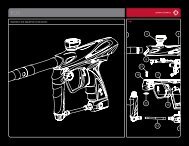
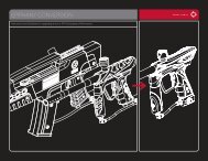
REv-i pARtS LiSt<br />
A. Dump Valve Bolt<br />
B. Bolt O-ring #1<br />
C. Bolt O-ring #2<br />
D. Bolt O-ring #3<br />
E. Clear Bolt Tube (Anodized Aluminum Bolt Tube<br />
not shown)<br />
F. Low-Rise Clamping Feedneck<br />
G. <strong>REV</strong>-i Body<br />
H. Dump Valve Plug/Rear Mounted Pressure<br />
Gauge<br />
I. Body / Frame Connector Screw #1<br />
J. Body / Frame Connector Screw #2<br />
K. Two-Way Solenoid<br />
L. OPR (Operating Pressure Regulator)<br />
M. Swivel Screw<br />
N. Macro-line Elbow Fitting<br />
O. <strong>REV</strong>-i Trigger Frame<br />
P. Trigger Adjustment Screws<br />
Q. Trigger Removal Screw<br />
R. SwitchBlade Trigger<br />
S. Trigger Guard<br />
T. Butterfly Grip Panel<br />
U. Grip Screws<br />
V. RAPS TM (Rapid Air Pressurizing System) ASA<br />
6 W W W . D A N G E R O U S P O W E R . C O M<br />
7
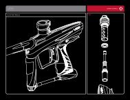
iNLiNE REgULAtOR<br />
A<br />
E<br />
B<br />
F<br />
C<br />
D<br />
ShiM StAck<br />
G<br />
H<br />
I<br />
J<br />
K<br />
OpR pARtS LiSt<br />
8 W W W . D A N G E R O U S P O W E R . C O M<br />
9<br />
A. C-clip<br />
B. Macro-line Elbow Fitting<br />
C. OPR Bottom Swivel Screw<br />
D. OPR Bottom Housing<br />
E. Regulator Seat O-ring<br />
F. Regulator Adjustment Screw<br />
G. OPR Main Body Housing<br />
H. OPR Piston Washers x 8<br />
I. OPR Piston<br />
J. OPR Piston Base Sealing Gasket<br />
K. OPR Top Housing Ring
cONtENtS OF pAckAgE<br />
Your REv-i package should include ALL of the following items:<br />
<strong>REV</strong>-i Marker Body<br />
3 Barrel Backs (sizes .69, .68, and .67)<br />
2 Barrel Tips (10.45 in. and 8.48 in.)<br />
11 Piece Ball-Tip Allen Key Wrench Set<br />
T-Handle Allen Wrench (5/16”)<br />
T-Handle Allen Wrench (5/32”)<br />
Color-matching Aluminum Sleeve<br />
Spare O-rings<br />
DP-40 Lubricant<br />
DP Key Chain<br />
Barrel Blocking Device<br />
Custom <strong>REV</strong>-i Carrying Case<br />
Owner’s Manual<br />
Registration Card<br />
10 W W W . D A N G E R O U S P O W E R . C O M<br />
11
EvERYthiNg YOU NEEd tO gEt StARtEd<br />
Prepare the following items in order to begin using your <strong>REV</strong>-i:<br />
• One 9V battery. Be sure that the battery is fresh and from a reputable manufacturer.<br />
• Paintball loading device. (Recommended minimum load rate of 25 BPS)<br />
• .68 caliber paintballs. Always use fresh, high-quality paint with proper bore size for best results.<br />
• Approved air tank utilizing COMPRESSED AIR or NITROGEN ONLY.<br />
iNStALLiNg thE bAttERY<br />
• Carefully remove the 2 hexagonal screws (3/32”) holding<br />
the left panel in place.<br />
• Locate battery harness and attach 9V battery to the<br />
connector pad. Do not use force!<br />
• Replace battery in grip frame as shown in illustration.<br />
• Replace grip frame and screws. Do not over tighten<br />
screws!<br />
AttAchiNg A pAiNtbALL LOAdER<br />
• Loosen thumbscrew counterclockwise by hand.<br />
• Release clamp on feedneck.<br />
• Insert feed tube of loader unit.<br />
• Close clamp securely. Loader should fit snug within<br />
feedneck.<br />
• If loader is too loose, remove and adjust thumbscrew.<br />
WARNING<br />
TAKE CARE NOT TO USE ExCESSIVE FORCE<br />
- DOING SO MAY CAUSE DAMAGE TO LOADER<br />
OR THE <strong>REV</strong>-i!<br />
12 W W W . D A N G E R O U S P O W E R . C O M<br />
13
cONNEctiNg MAcRO-LiNE tO high pRESSURE<br />
REgULAtOR ANd QUick RELEASE FLip LEvER ASA<br />
(RApS tM )<br />
• Pull back the collect section of the macro-line elbow<br />
located on your RAPS TM ASA.<br />
• Keeping the collet back, insert macro-line hose firmly into<br />
the fitting and release the collet. Be sure that the hose is<br />
seated all the way to the end of elbow fitting.<br />
• Repeat the same process on the macro-line elbow<br />
located on your HPR to connect the RAPS TM ASA.<br />
WARNING<br />
BE SURE TO REGULARLY INSPECT THE<br />
CONDITION OF YOUR MACRO-LINE HOSE TO<br />
ENSURE PROPER FITMENT. ALWAYS CHECK<br />
TO MAKE SURE THE MACRO-LINE HOSE IS<br />
SEATED ALL THE WAY TO THE END OF THE<br />
ELBOW.<br />
AttAchiNg AiR tANk tO RApS tM FLip LEvER ASA<br />
• Swing flip lever to the ‘release’ position.<br />
• Attach air tank by carefully screwing it into the threaded<br />
portion of the RAPS TM ASA. Make sure tank fitment is<br />
tight and all the way in.<br />
• Return flip lever of the RAPS TM ASA to the ‘close’ position.<br />
• A brief sound of air entering the system is normal. The<br />
<strong>REV</strong>-i is now pressurized.<br />
WARNING<br />
NITROGEN OR COMPRESSED AIR TANKS ONLY!<br />
NEVER USE CO2.<br />
14 W W W . D A N G E R O U S P O W E R . C O M<br />
15
SWitchiNg YOUR REv-i ON/OFF<br />
• Press and hold the Power Button until the <strong>REV</strong>-i turns on. Release the power button to continue.<br />
• To power OFF your <strong>REV</strong>-i, press and hold the Power Button until your marker shuts off.<br />
tURNiNg EYES ON/OFF<br />
• The <strong>REV</strong>-i uses a break beam eye sensor system to<br />
detect paintballs in the firing position. When the eye<br />
sensors are turned on, the circuit board will inhibit the<br />
firing of the bolt when no paintballs are detected. This<br />
prevents unintended paintball breakage in the breech<br />
of the marker. For optimum results during play, always<br />
leave the eyes in the ‘ON’ position. When ‘dry firing’, it<br />
will be necessary to switch the eye sensors to the ‘OFF’<br />
position.<br />
• Tap the Eye Button to toggle the eye function between<br />
ON or OFF. Your marker will display the ‘EYES ON’ icon<br />
on the OLED display when enabled and will fire at the<br />
‘EYES ON’ rate of fire.<br />
POWER<br />
EYES<br />
• When the eye function is disabled, the ‘EYES OFF’ icon will appear on the OLED display and your marker will<br />
fire at the ‘EYES OFF’ rate of fire.<br />
• The multi-color LED will flash to indicate ‘EYES OFF’ (slow flash) or ‘iFAULT’ (fast flash - see page 37) or<br />
stay on continuously if breech is empty.<br />
FiRiNg YOUR REv-i<br />
• While the <strong>REV</strong>-i is ON, tap the Power Button to scroll thru all the<br />
enabled firing modes.<br />
• Select desired firing mode.<br />
• Depress the trigger to fire the <strong>REV</strong>-i.<br />
• The entire firing operation can be programmed electronically for<br />
optimal results.<br />
Firing Mode BPS<br />
Player Profile<br />
Tourney Lock<br />
16 W W W . D A N G E R O U S P O W E R . C O M<br />
17<br />
Battery<br />
Eye Icon
vELOcitY AdJUStMENt<br />
• Locate the (1/4”) allen key wrench included with your <strong>REV</strong>-i.<br />
• Adjust screw located at the bottom of Operating Pressure<br />
Regulator (OPR) to increase or decrease velocity.<br />
• Turn screw counterclockwise towards the (+) sign to<br />
increase velocity.<br />
• Turn screw clockwise towards the (-) sign to decrease<br />
velocity.<br />
Helpful Hint: The Rear Mounted Pressure Gauge (RMPG)<br />
provides a guideline to the velocity of the projected paintballs<br />
through its correlation to air pressure as measured in Pounds<br />
per Square Inch (PSI). This is for reference only and is NOT<br />
RECOMMENDED as a substitute for an approved chronograph<br />
device.<br />
WARNING<br />
FAILURE TO FOLLOW REGULATIONS RE-<br />
GARDING MAxIMUM ALLOWABLE VELOCITY,<br />
CALCULATED IN FEET PER SECOND (FPS), MAY<br />
RESULT IN DAMAGE OF PAINTBALL MARKER,<br />
SERIOUS INJURY OR DEATH. BE RESPONSIBLE<br />
AND ALWAYS USE A CHRONOGRAPH TO DE-<br />
TERMINE ACCURATE VELOCITY BEFORE PLAY.<br />
DP ENGINEERING RECOMMENDS THAT THE<br />
VELOCITY NEVER ExCEED 300 FPS.<br />
tRiggER AdJUStMENt<br />
• Note the three adjustment screws (marked A, B, and C) in<br />
the vicinity of the SWITCHBLADE TM Trigger.<br />
• Screw A (5/64”) adjusts the amount of trigger travel prior<br />
to the marker firing. Turning this screw clockwise will<br />
reduce the amount of trigger travel. Turning this screw<br />
counterclockwise will increase the amount of trigger<br />
travel.<br />
• Screw B (5/64”) sets the amount of trigger travel after the<br />
marker has been fired. Turning the screw clockwise will<br />
reduce the amount of trigger travel. Turning the screw<br />
counterclockwise will increase the amount of trigger<br />
travel.<br />
NOTE<br />
BE CAREFUL NOT TO TURN THE SCREW TOO<br />
FAR IN EITHER DIRECTION, AS DOING SO MAY<br />
PUSH THE TRIGGER PAST THE FIRING POINT<br />
AND CAUSE OPERATIONAL FAILURE.<br />
18 W W W . D A N G E R O U S P O W E R . C O M<br />
19<br />
A<br />
B
tRiggER AdJUStMENt (cONtiNUEd)<br />
• Screw C (3/32”) adjusts the strength of the trigger’s return<br />
to rest by either reducing or increasing the magnetic pull.<br />
Turning this screw counterclockwise will decrease the<br />
strength. Turning this screw clockwise will increase the<br />
strength. Do not turn the screw too far - doing so may<br />
weaken the magnetic pull and prevent the trigger from<br />
being able to fully return to rest.<br />
• <strong>REV</strong>-i’s SWITCHBLADE Trigger. This revolutionary trigger system allows the user to quickly switch<br />
between two trigger styles without the use of tools or disassembly. Simply flip the trigger and lock in place<br />
the desired trigger style.<br />
C<br />
pROgRAMMiNg YOUR REv-i<br />
Please refer to <strong>REV</strong>-i Circuit Board Programming Flow-Chart for a complete overview.<br />
To enter Programming Mode, POWER ON the <strong>REV</strong>-i while pulling the trigger down. Release the power button and<br />
trigger to continue.<br />
NOTE<br />
YOUR MARKER WILL NOT START IN PROGRAMMING MODE IF THE TOURNEY MODE LOCK SWITCH<br />
(SEE PAGE 38) IS IN THE ‘ON’ POSITION.<br />
To exit Programming Mode, either POWER OFF the <strong>REV</strong>-i or scroll through modes until the ‘x’ appears in the<br />
upper right corner of the screen. When the ‘x’ is displayed, pull and hold the trigger to return to live firing mode.<br />
MENU NAvigAtiON<br />
Pull and release the trigger to scroll through the available menu options. An arrow on the left side of the display will<br />
indicate your current selection. To select a menu option, simply pull and hold the trigger. To adjust the setpoint, tap<br />
the Power Button to increase the value or tap the Eye Button to decrease the value. Once the desired<br />
setpoint value is reached, simply scroll to another setpoint, or exit. Once you scroll past the last option in a menu, a<br />
“Back Arrow” icon will appear in the upper left corner of the OLED display. When selected, the “Back Arrow”<br />
option returns you to the previous menu.<br />
20 W W W . D A N G E R O U S P O W E R . C O M<br />
21
REv-i ciRcUit bOARd pROgRAMMiNg<br />
FLOW-chARt<br />
START MENU<br />
PROFILE LOAD MENU<br />
HOT START MENU<br />
PROGRAM MENU<br />
TRIGGER TRAINER<br />
STATISTICS<br />
PEAK<br />
0 0<br />
0 0<br />
A V G<br />
T<br />
T<br />
M<br />
PROGRAM MENU<br />
SET PROFILE A<br />
SET PROFILE B<br />
SET PROFILE C<br />
SET PROFILE D<br />
SET PROFILE E<br />
SET PROFILE F<br />
GLOBAL SETUP MENU<br />
TUNE ASSIST<br />
RESET MENU<br />
STATISTICS<br />
PEAK PULL RATE XX<br />
TOTAL PULLS XXXXX<br />
TOTAL SHOTS XXXXX<br />
HOT START MENU<br />
UNCAPPED FIRING<br />
BREAKOUT MODE<br />
DRY FIRE MODE<br />
PROFILE LOAD MENU<br />
LOAD PROFILE A<br />
LOAD PROFILE B<br />
LOAD PROFILE C<br />
LOAD PROFILE D<br />
LOAD PROFILE E<br />
LOAD PROFILE F<br />
S 1<br />
E 3<br />
M .<br />
I 3<br />
RESET MENU<br />
PROFILE A<br />
PROFILE B<br />
PROFILE C<br />
PROFILE D<br />
PROFILE E<br />
PROFILE F<br />
GLOBAL SETPOINTS<br />
STATISTICS<br />
DEFAULT ALL<br />
GLOBAL SETUP MENU<br />
GLOBAL SETPOINTS<br />
BREAKOUT MODE<br />
TOURNEY RULES<br />
TUNE ASSIST<br />
START<br />
DWELL XX<br />
BOLT RETURN XX<br />
PROFILE {X} SETUP<br />
MARKER SETPOINTS<br />
FIRING SETPOINTS<br />
FIRING MODE ENABLE<br />
CONFIRM RESET<br />
TOURNEY RULE MENU<br />
TOURNEY 1 RULES<br />
TOURNEY 2 RULES<br />
FORMAT CHAR 1 N<br />
FORMAT CHAR 2 X<br />
FORMAT CHAR 3 L<br />
TOURNEY 3 RULES<br />
FORMAT CHAR 1 M<br />
FORMAT CHAR 2 I<br />
FORMAT CHAR 3 L<br />
FORMAT CHAR 4 L<br />
RAMP SEMI SHOT 3<br />
RAMP PULL RATE 6<br />
RAMP MODE PCNT<br />
RAMP VALUE 1<br />
RAMP TIMER<br />
0<br />
22 W W W . D A N G E R O U S P O W E R . C O M<br />
23<br />
YES<br />
MODE 1 RULES<br />
MODE 2 RULES<br />
MODE 3 RULES<br />
BREAKOUT SETUP<br />
ENABLE OFF<br />
START PULLS 3<br />
ADDED BPS 2<br />
FIRING MODE AUTO<br />
BREAKOUT END 0<br />
AUTO CLEAR OFF<br />
GLOBAL SETPOINTS<br />
START PROFILE A<br />
TOURNY PROFILE A<br />
SPLASH SCREEN ON<br />
GAME TIMER<br />
0<br />
TMR START PULL 1<br />
COUNTER MEMO 0<br />
FORMAT CHAR 1<br />
FORMAT CHAR 2<br />
FORMAT CHAR 3<br />
FORMAT CHAR 4<br />
RAMP SEMI SHOT<br />
RAMP PULL RATE<br />
RAMP MODE<br />
RAMP VALUE<br />
RAMP TIMER<br />
P<br />
S<br />
P<br />
3<br />
3<br />
0<br />
BRST<br />
3<br />
1<br />
FIRING MODES<br />
SEMI<br />
ON<br />
BURST ON<br />
REACTIVE ON<br />
AUTO<br />
ON<br />
RAMPING ON<br />
TOURNEY 1 ON<br />
TOURNEY 2 ON<br />
TOURNEY 3 ON<br />
FORMAT CHAR 4<br />
RAMP SEMI SHOT<br />
RAMP PULL RATE<br />
RAMP MODE<br />
RAMP VALUE<br />
RAMP TIMER<br />
3<br />
0<br />
AUTO<br />
1<br />
1<br />
FIRING SETPOINTS<br />
TOURNEY MODE SEMI<br />
CAPPED FIRING ON<br />
BPS EYES ON 15<br />
BPS FINE<br />
0<br />
BPS EYES OFF 10<br />
BURST SHOTS 3<br />
REACTIVE SHOTS 1<br />
RAMP SEMI SHOT 3<br />
RAMP PULL RATE 4<br />
RAMP MODE PCNT<br />
RAMP VALUE<br />
1<br />
RAMP TIMER<br />
1<br />
MARKER SETPOINTS<br />
TRIG DEBOUNCE 20<br />
SOLENOID DWELL 18<br />
ABS DWELL 0<br />
ABS RESET TIME 10<br />
BREECH DELAY 3<br />
BOLT RETURN 20<br />
AUTO SHUTOFF 0<br />
EYE MODE STD<br />
EYE PROCESS STD<br />
LED CONTROL WHIT<br />
AUDIO CONTROL ON<br />
OLED INTENSITY 25
StARt MENU<br />
Profile Load Menu<br />
This option lets you load a profile. You can define up to six individual<br />
profiles. Each profile stores a complete collection of setpoints and<br />
allows instant reconfiguration of settings and preferences.<br />
Hot Start Menu<br />
This option lets you quickly access the following options:<br />
- Uncapped Firing:<br />
Instantly uncaps the rate of fire on your marker.<br />
- Breakout Mode:<br />
Instantly turns on the currently defined Breakout Mode.<br />
- Dry Fire Demo:<br />
Instantly bypasses all eye processing on your marker and fires at<br />
the ‘EYES ON’ rate of fire.<br />
StARt MENU (cONtiNUEd)<br />
Program Menu<br />
This menu provides access to all the marker set-points. Each time the<br />
marker is programmed, the settings are stored into a unique profile.<br />
You can program up to six individual profiles. From this menu you<br />
can also access the Global Set-points (those that apply to all marker<br />
operations), the Tuning Assist function and the Reset Menu.<br />
Trigger Trainer Mode (TTM)<br />
This option puts you into “training” mode that lets you measure how<br />
fast you can pull the trigger. This mode will capture your Average<br />
and Peak pull rates, and display a bar graph based on your current<br />
pull rate. To start a training cycle, pull the trigger repeatedly for a<br />
short burst. When you stop pulling, the marker will update the OLED<br />
display with your pull rate data. Pull another trigger burst to measure<br />
your rate again.<br />
24 W W W . D A N G E R O U S P O W E R . C O M<br />
25
StARt MENU (cONtiNUEd)<br />
Statistics<br />
This option displays the following statistical information about your<br />
marker:<br />
- Peak Pull Rate<br />
This displays the highest pull rate achieved since the last reset.<br />
- Total Pulls<br />
This displays the total number of trigger pulls since the last reset.<br />
- Total Shots<br />
This displays the total number of bolt cycles / shots fired since the<br />
last reset. This total is also used for your Memo function.<br />
All of these statistical counters can be reset to zero from the “Reset Menu”.<br />
pROFiLE LOAd MENU<br />
This option allows you to choose which profile you wish to load should<br />
you want to manually override the “Start Profile” setpoint in the Global<br />
Setpoint section.<br />
gLObAL SEtUp MENU<br />
Start Menu > Program Menu > Global Setup Menu<br />
This menu provides access to setpoints that apply to all profiles and<br />
marker operations. They are organized into three groups:<br />
1.Global Setpoints<br />
Start Menu > Program Menu > Global Setup Menu > Global Setpoint<br />
- Start Profile<br />
This setpoint determines which profile your marker will use when it<br />
starts.<br />
- Tourney Profile<br />
This setpoint determines which profile your marker will use when the<br />
TOURNEY MODE LOCK SWITCH is set to ‘ON’.<br />
- Splash Screen<br />
This determines if the splash screen is displayed at marker startup.<br />
26 W W W . D A N G E R O U S P O W E R . C O M<br />
27
gLObAL SEtUp MENU (cONtiNUEd)<br />
- Game Timer<br />
Sets the time (in minutes) for your game timer. A value of zero<br />
disables the game timer feature.<br />
- TMR Start Pull<br />
Determines which trigger pull will start the game timer after marker<br />
start up. This allows you to fire “x” number of clearing shots without<br />
starting the timer.<br />
- Counter Memo<br />
This setpoint lets you activate the “Memo” icon on the OLED display<br />
after a desired number of marker cycles have occurred. This<br />
setpoint is programmed in thousands (i.e. 2 = 2000 marker cycles).<br />
gLObAL SEtUp MENU (cONtiNUEd)<br />
2.Breakout Mode<br />
These setpoints allow you to define your own custom Breakout Mode:<br />
- Enabled<br />
This setpoint turns on/off the Breakout Mode operation.<br />
- Start Pulls<br />
Enable the Breakout Mode to choose which trigger pull will activate<br />
this mode.<br />
- Added BPS<br />
While the Breakout Mode is active, this setpoint lets you add<br />
additional balls per second to your programmed rate of fire.<br />
- Firing Mode<br />
This sets the mode the marker will fire in once Breakout Mode is<br />
activated.<br />
- Breakout End<br />
This setpoint lets you choose how the Breakout Mode will end.<br />
Choose 0 to end the Breakout Mode operation once the trigger<br />
is idle 0.2 seconds, or choose the length of time (in seconds) the<br />
Breakout Mode will remain active.<br />
28 W W W . D A N G E R O U S P O W E R . C O M<br />
29
gLObAL SEtUp MENU (cONtiNUEd)<br />
- Auto Clear<br />
When this is set to ON, the Breakout function will have to be<br />
re-enabled via the programming menu or through the Hot Start<br />
option. If Auto Clear is set to OFF, simply power cycle your marker<br />
to re-enable the Breakout mode.<br />
3.Tourney Rules<br />
Start Menu > Program Menu > Global Setup Menu > Tourney Rules<br />
The <strong>REV</strong>-i provides fully programmable tournament operations,<br />
allowing you to stay compliant in the event of any future tournament<br />
rule changes. Default support is provided for PSP, NxL and<br />
Millennium tournament formats. The user can also reconfigure these<br />
rules for other tournament formats or any new tournament format that<br />
is adopted in the future.<br />
- Ramp Semi Shots<br />
Defines the number of semi shots required before any ramping is<br />
allowed.<br />
- Ramp Pull Rate<br />
This is the trigger pull rate (trigger pulls per second) that needs to<br />
be achieved before ramping. Any semi shots defined must first<br />
be satisfied prior to ramping by pull rate. If this setpoint is zero,<br />
the marker will ramp immediately after the defined number of<br />
semishots are satisfied.<br />
gLObAL SEtUp MENU (cONtiNUEd)<br />
- Ramp Mode<br />
Determines which firing mode to ramp to: Burst, Reactive, Full Auto,<br />
or Percent ramping.<br />
- Ramp Value<br />
In Burst Mode, it is the number of shots in a burst. In Reactive<br />
Mode, it is the number of shots fired with each trigger pull and<br />
release. In Percent ramping, it is the percentage of ramping used<br />
(Percentage = Ramp Firing Value x 100).<br />
- Ramp Timer<br />
Determines the amount of time the trigger can be at rest and still<br />
remain in the current ramping stage before reverting back to Semi<br />
Mode. This time value is entered in seconds. If this setpoint is<br />
zero, it will reset ramping when the trigger is released, or when your<br />
trigger pull rate drops below the Ramp Pull Rate setpoint.<br />
30 W W W . D A N G E R O U S P O W E R . C O M<br />
31
tUNE ASSiSt<br />
Start Menu > Program Menu > Tune Assist<br />
This option lets you quickly determine the best Dwell and Bolt Return<br />
Delay setting for optimal efficiency. Keep in mind that the current setting<br />
for Dwell and Bolt Return Delay will be overwritten in all profiles when<br />
this action is completed. To start, your marker MUST BE UNLOADED.<br />
Next, connect your marker to your air source.<br />
NOTE<br />
BE SURE YOU ARE STARTING WITH A FULL TANK OF AIR AND ADJUST YOUR MARKER’S REGULATOR<br />
TO FIRE PAINT AT APPROxIMATELY 285 FPS BEFORE YOU BEGIN. YOU MAY NEED TO MAKE MINOR<br />
ADJUSTMENTS TO YOUR REGULATOR SETTINGS WHEN YOU’VE COMPLETED THE TUNE ASSIST<br />
PROCESS.<br />
• When firing the marker in Tune Assist Mode, pause at least 1 second between trigger pulls.<br />
• Select START to proceed with Tune Assist. The Dwell value will start at 5ms. Each time you pull the trigger,<br />
your marker will dry fire a 3 shot burst and will increase the Dwell by 1ms. Keep pulling the trigger until your<br />
marker fires the burst with a consistent “pop” or report. You can also press the Eye Button to decrease the<br />
current Dwell value should you want to repeat the procedure for a given range of Dwell values. Press the<br />
Power Button to move on to the Bolt Return Delay adjustment.<br />
• Pull the trigger again firing a 3 shot burst. This time your Bolt Return Delay will start at the maximum value<br />
and decrease 1ms with each pull. Continue to pull the trigger until the LED flashes and the onboard speaker<br />
beeps. Your marker will automatically restart with the new optimal values.<br />
RESEt MENU<br />
Start Menu > Program Menu > Reset Menu<br />
The Reset Menu allows you to individually reset profiles, statistics, or<br />
your entire marker to factory default settings. Trigger scroll to the item<br />
you want to reset. To select the item you wish to reset, pull and hold the<br />
trigger. A confirmation screen will then ask you to confirm that you want<br />
to reset the item. Pull and hold to confirm.<br />
32 W W W . D A N G E R O U S P O W E R . C O M<br />
33
MARkER SEtpOiNtS<br />
Start Menu > Program Menu > Set Profile (x) > Marker Setpoints<br />
- Trigger Debounce<br />
This value sets amount of time (in milliseconds) the trigger must<br />
remain inactive prior to accepting a new trigger pull. Lowering this<br />
value can cause your marker to fire erratically when making<br />
successive trigger pulls. Raising this value will prevent erratic firing<br />
and provide reliable firing in sync with your trigger pulls.<br />
- Solenoid Dwell<br />
This setting allows you to adjust how long the solenoid is energized<br />
(in milliseconds). Higher Dwell times will consume more power and<br />
air when the solenoid is energized. Lower Dwell times consume<br />
less power when the solenoid is energized. Lowering this value too<br />
much may prevent the solenoid valve from opening altogether.<br />
- Anti Bolt Stick Dwell<br />
This setting allows you to add additional Dwell time (in milliseconds)<br />
to your solenoid Dwell setting. This will only affect the first shot fired<br />
after the Bolt Stick Reset Time is exceeded.<br />
NOTE<br />
YOU SHOULD ONLY USE THIS SETTING IF YOU<br />
ExPERIENCE FIRST SHOT DROP OFF.<br />
MARkER SEtpOiNtS (cONtiNUEd)<br />
Start Menu > Program Menu > Set Profile (x) > Marker Setpoints<br />
- Anti Bolt Stick Reset Time<br />
This setting allows you to set the amount of time the trigger can<br />
remain idle before adding the Bolt Stick Dwell setting. This value is<br />
ignored if the Bolt Stick Dwell is zero.<br />
- Breech Load Delay<br />
This setpoint establishes the amount of time (in milliseconds)<br />
between the eyes sensing the ball in the breech and activation<br />
of the bolt. This ensures a ball has dropped fully into the breech<br />
before the marker fires.<br />
- Bolt Return Delay<br />
This setpoint establishes the amount of time (in milliseconds) after<br />
firing a round that the marker waits to see the bolt transition back<br />
past the eyes. This value can be lowered when using high<br />
performance aftermarket bolts or when a proper tuning procedure is<br />
performed. This delay also provides the time out period to<br />
determine if an eye fault (iFault) has occurred.<br />
- Auto Shut Off<br />
Allows you to adjust if or when your marker will automatically<br />
POWER OFF after no firing activity. Auto Shutoff values range from<br />
0 to 60, with each increment adding 1 minute of time to the delay (1<br />
to 60 min.). A value of 0 defeats the Auto Shutoff feature, and your<br />
marker will remain on until you manually POWER OFF.<br />
34 W W W . D A N G E R O U S P O W E R . C O M<br />
35
MARkER SEtpOiNtS (cONtiNUEd)<br />
Start Menu > Program Menu > Set Profile (x) > Marker Setpoints<br />
- Eye Mode<br />
Your Rev-I has 4 eye control modes:<br />
Option 1 – IFLT (iFault TM ): While your eyes are functioning, your<br />
marker will fire at the BPS ‘EYES ON’ rate. If your marker’s eyes<br />
become disabled, iFault will automatically switch to the BPS<br />
‘EYES OFF’ rate automatically. If your eye functionality returns,<br />
iFault will automatically resume firing at the BPS ‘EYES ON’ rate.<br />
Option 2 – STD (Standard): While your eyes are functioning, your<br />
marker will fire at the BPS ‘EYES ON’ rate. If your eyes stop<br />
working, your marker will stop firing until you manually bypass the<br />
eye operation.<br />
Option 3 – OFF: All eye functions are disabled, and the marker<br />
operates at the BPS ‘EYES OFF’ rate of fire.<br />
Option 4 – DEMO: This allows you to fire the marker at the BPS<br />
‘EYES ON’ rate while all eye processing is bypassed. This is a dry<br />
fire mode only.<br />
MARkER SEtpOiNtS (cONtiNUEd)<br />
Start Menu > Program Menu > Set Profile (x) > Marker Setpoints<br />
- Eye Process<br />
Standard processing (STD) checks for a “ball in breech” status after<br />
each trigger pull before firing the marker. This process is slightly<br />
slower since it forces the board to wait for the breech delay time for<br />
each bolt cycle.<br />
Advanced processing (ADV) looks for a “ball in breech” status<br />
immediately after the bolt cycle is complete. Once this condition is<br />
met, the marker is allowed to fire again immediately if required (“ball<br />
in breech” status is queued).<br />
- LED Control<br />
Along with the OLED display, your marker has a multicolor LED.<br />
This color can be customized to your choosing (up to 7 colors). The<br />
LED provides quick eye status indication in conjunction with the Eye<br />
Status indicator on your display. The LED Eye Status indicators are:<br />
• LED Solid = No ball in breech<br />
• LED Slow Flashing = Eyes have been manually turned off<br />
• LED Fast Flashing = Indicates an iFault TM alert<br />
• LED Off = Ball is properly seated in the breech and marker is<br />
ready to fire<br />
- Audio Control<br />
Audio feedback can be enabled or disabled. Feedback occurs<br />
during all programming and firing operations.<br />
- OLED Intensity<br />
Allows you to change the intensity level of your OLED display.<br />
36 W W W . D A N G E R O U S P O W E R . C O M<br />
37
FiRiNg SEtpOiNtS<br />
Start Menu > Program Menu > Set Profile (x) > Firing Setpoints<br />
- Tourney Mode<br />
Determines what mode will be used for tournament play when the<br />
Tourney Mode Lock Switch is ON. Activate the Tournament Mode by<br />
placing the switch in the ‘ON’ position and power cycling the marker.<br />
Tournament Mode deactivates all programming operations.<br />
Tourney Mode Lock Switch<br />
To access this switch, remove grip from the grip frame using supplied<br />
allen key wrench (3/32”). Flip the marker so you are viewing<br />
the side opposite the 9V battery. On the back of the board, you will<br />
see a small piece of protective tape covering a tiny switch. By<br />
default, the switch will be in the ‘OFF’ position (to the right). To turn<br />
the switch to the ‘ON’ position, carefully nudge the switch using a<br />
small sharp object towards the dot (on the left).<br />
FiRiNg SEtpOiNtS (cONtiNUEd)<br />
Start Menu > Program Menu > Set Profile (x) > Firing Setpoints<br />
- Capped Firing<br />
This option allows you to cap the firing rate at the BPS ‘EYES ON’<br />
setpoint. If you wish to fire your marker uncapped at its highest<br />
mechanical rate of fire, you can turn the option OFF.<br />
- BPS Eyes On<br />
This sets the ‘EYES ON’ rate of fire in BPS (balls per second) for all<br />
firing modes.<br />
- BPS Fine<br />
This adds a fractional BPS to the BPS ‘EYES ON’ setting. For<br />
example, a value of 1 would add .1 to the BPS ‘EYES ON’ rate of<br />
fire.<br />
- BPS Eyes Off<br />
This sets the ‘EYES OFF’ rate of fire in BPS (balls per second) for<br />
all firing modes.<br />
- Burst Shots<br />
This value sets the number of rounds fired for each trigger pull in<br />
Burst Mode.<br />
- Reactive Shots<br />
This value sets the number of rounds fired for each trigger pull and<br />
release in Reactive Mode.<br />
38 W W W . D A N G E R O U S P O W E R . C O M<br />
39
FiRiNg SEtpOiNtS (cONtiNUEd)<br />
Start Menu > Program Menu > Set Profile (x) > Firing Setpoints<br />
- Ramp Semi Shot<br />
Defines the number of semi shots required before any ramping is<br />
allowed.<br />
- Ramp Pull Rate<br />
This is the trigger pull rate (trigger pulls per second) that needs to<br />
be achieved before ramping. Any semi shots defined must first be<br />
satisfied prior to ramping by pull rate. Likewise, if this setpoint is<br />
zero, the marker will ramp immediately after the defined number of<br />
semi shots are satisfied.<br />
- Ramp Mode<br />
Determines which firing mode to ramp to: Burst, Reactive, Full Auto,<br />
or Percent ramping.<br />
- Ramp Value<br />
This value is associated with the Ramp Mode. In Burst Mode, it is<br />
the number of shots in a burst. In Reactive Mode, it is the number<br />
of shots fired with each trigger pull and release. In Percent ramping,<br />
it is the percentage of ramping used (Ramp Firing Value x 100).<br />
- Ramp Timer<br />
Determines the amount of time the trigger can be at rest and still<br />
remain in the current ramping stage before reverting back to Semi<br />
Mode. This time value is entered in seconds.<br />
FiRiNg MOdE ENAbLE<br />
Start Menu > Program Menu > Set Profile (x) > Firing Mode Enable<br />
Allows you to enable/disable any firing mode in a profile. A disabled<br />
firing mode is skipped when scrolling thru firing modes.<br />
NON-AdJUStAbLE FEAtURES<br />
- Forced Shot<br />
You can force the marker to fire during empty breech conditions by holding the trigger down for one second.<br />
Forced Shot is useful for initial paint loading using sound activated hoppers.<br />
- Trigger Buffering<br />
This allows you to fire a smooth stream of paint by queuing a valid trigger pull during a firing cycle.<br />
40 W W W . D A N G E R O U S P O W E R . C O M<br />
41
cARE ANd MAiNtENANcE<br />
Your <strong>REV</strong>-i was designed to be reliable, easy to maintain, and easy to repair. Routine maintenance will ensure<br />
many years of performance and enjoyment. When in doubt, always seek the assistance of a certified technician<br />
from a reputable pro shop, or contact DP Engineering Customer Service.<br />
Degassing the <strong>REV</strong>-i<br />
Always be sure to completely de-gas your marker before performing maintenance or service repair. Carefully follow<br />
the instructions below in sequence to ensure that all remaining air has been removed from the entire operation:<br />
1. Flip the RAPS TM ASA to the “OFF” position. This disconnects the air system from the marker.<br />
2. Remove the paintball loading device and check to make sure there are no paintballs within the breech.<br />
3. Unscrew the air system from the RAPS TM ASA.<br />
4. Point the marker in a safe direction, then fire 1-2 shots to remove air from the OPR. Be aware that the marker<br />
may still fire without an air system attached!<br />
5. POWER OFF the marker.<br />
IMPORTANT NOTES BEFORE SERVICING YOUR MARKER :<br />
• USE OF HYDROCARBON BASED OILS, SUCH AS AUTOMOTIVE ENGINE OIL, WD-40, VASELINE,<br />
ETC. CAN SEVERELY DAMAGE INTERNAL SEALS AND ARE NOT RECOMMENDED.<br />
• ALWAYS USE A HIGH QUALITY LUBE OF CORRECT VISCOSITY, SPECIFICALLY DESIGNED FOR<br />
PAINTBALL MARKERS. ALWAYS USE DP-40 LUBE (SUPPLIED) OR ANOTHER HIGH QUALITY LUBE<br />
OF CORRECT VISCOSITY SPECIFICALLY DESIGNED FOR PAINTBALL MARKERS.<br />
• DO NOT APPLY ExCESSIVE LUBRICANT.<br />
• ALWAYS INSPECT AND CLEAN YOUR MARKER AFTER EACH USE.<br />
• NEVER APPLY ExCESSIVE FORCE WHEN REMOVING OR REPLACING SCREWS. DOING SO MAY<br />
STRIP THE SCREW HEADS OR DAMAGE THREADS.<br />
• ALWAYS USE THE APPROPRIATE TOOLS AND THE CORRECT SIZE.<br />
• REFRAIN FROM SUBMERSING ENTIRE MARKER IN LIQUID. KEEP SENSITIVE ELECTRONICS<br />
SUCH AS SOLENOID AND CIRCUIT BOARD FREE FROM MOISTURE.<br />
• NEVER ALLOW SOMEONE WHO IS UNFAMILIAR WITH YOUR MARKER TO PERFORM<br />
MAINTENANCE OR REPAIR WORK. WHEN IN DOUBT, CONTACT DP ENGINEERING CUSTOMER<br />
SERVICE.<br />
42 W W W . D A N G E R O U S P O W E R . C O M<br />
43
cLEANiNg thE EYE-SENSOR bREAk bEAM SYStEM<br />
The function of the break beam sensor eyes is to allow the<br />
firing circuit to ‘time’ the activation of the solenoid. This<br />
prevents ‘chopping’ of paint, which is caused by the bolt cycling<br />
within the breech without the paintball being actually seated in<br />
the proper firing position. When the eye sensors are ON, the<br />
gun will not fire if the beam does not sense a paintball. To<br />
ensure proper function, the eye sensors should be cleaned<br />
after every other use, or when paintballs have been broken<br />
within the marker. More frequent cleaning may be necessary<br />
when using paintballs that have ‘oily residue’ on the surface<br />
of the shell. To avoid malfunction, always use fresh and clean<br />
paint from a reliable manufacturer.<br />
To clean the eyes:<br />
1. Locate the eye cover plates on either side of your <strong>REV</strong>-i<br />
body. (SEE PIC A)<br />
2. Using provided allen key wrench (5/64”), carefully remove<br />
the eye cover screw on one side by inserting ball point tip<br />
and turning wrench handle counterclockwise.<br />
(SEE PIC B)<br />
3. Lift eye cover plate, exposing eye wires, spring, and ball<br />
detent. (SEE PIC C)<br />
A<br />
B<br />
C<br />
cLEANiNg thE EYE-SENSOR bREAk bEAM SYStEM<br />
(cONtiNUEd)<br />
4. Carefully life eye wires and pull out the eye sensors from<br />
the socket. Be careful not to lose the spring and the ball<br />
detent. (SEE PIC D)<br />
5. With a cotton swab, gently wipe the back and front side of<br />
the eye sensor and the eye socket to remove any debris<br />
or residue. (SEE PIC E)<br />
6. Replace eye sensors back to original position. Be sure<br />
the eyes are aligned correctly and facing the direction of<br />
the breech.<br />
7. Replace eye cover plate in original position and gently<br />
tighten eye cover screws clockwise. DO NOT OVER-<br />
TIGHTEN! (SEE PIC F)<br />
8. Repeat the same procedure on the other side.<br />
HELPFUL HINT<br />
DO NOT PULL ON THE EYE WIRES. USE A<br />
SMALL PICK OR SCREW DRIVER TO GENTLY<br />
LIFT THE WIRES UP. THIS WILL LIFT THE EYE<br />
SENSORS OUT OF THE EYE SOCKET.<br />
44 W W W . D A N G E R O U S P O W E R . C O M<br />
45<br />
4<br />
D<br />
E<br />
F
cLEANiNg thE bALL dEtENtS<br />
The ball detents and spring should be inspected during the<br />
cleaning of the eye sensors. Replace these parts should you<br />
notice any damage, no matter how slight.<br />
1. Locate the eye cover plates on either side of your <strong>REV</strong>-i<br />
body.<br />
2. Using provided allen key wrench (5/64”), carefully remove<br />
the eye cover screw on one side by inserting ball point tip<br />
and turning wrench handle counterclockwise.<br />
(SEE PIC A)<br />
3. Lift eye cover plate, exposing eye wires, spring, and ball<br />
detent. (SEE PIC B)<br />
4. Remove spring by carefully lifting it up by hand or with<br />
the aid of small tweezers. (SEE PIC C)<br />
A<br />
B<br />
C<br />
cLEANiNg thE bALL dEtENtS (cONtiNUEd)<br />
5. Place finger within breech, and gently push on the detent<br />
from the inside of marker body. Remove ball detent.<br />
(SEE PIC D)<br />
6. Check the spring for proper tension and the ball detent<br />
for any damage. Replace with new part(s) if necessary.<br />
7. With a cotton swab, clean the spring, ball detent, and<br />
detent groove. (SEE PIC E)<br />
8. Replace detent back to original position, with the circular<br />
side down towards the breech.<br />
9. Replace spring over the detent in the original position.<br />
10. Replace eye cover plate in original position and gently<br />
tighten eye cover screws clockwise. DO NOT OVER-<br />
TIGHTEN! (SEE PIC F)<br />
11. Repeat the same procedure on the other side.<br />
46 W W W . D A N G E R O U S P O W E R . C O M<br />
47<br />
D<br />
E<br />
F
OpERAtiNg pRESSURE REgULAtOR (OpR)<br />
diSASSEMbLY ANd MAiNtENANcE<br />
As its name implies, the OPR regulates the amount of air-flow, which determines paintball velocity. Regular<br />
inspection and cleaning of your OPR is an essential part of keeping your <strong>REV</strong>-i running in top condition. Follow the<br />
easy steps outlined below to ensure that your OPR remains trouble-free.<br />
GENERAL DISASSEMBLY OF OPR<br />
1. Before disassembly of your regulator, be sure to<br />
disconnect the macro-line hose from the elbow fitting<br />
attached to your regulator. This is accomplished by<br />
pulling back on the collet of the elbow fitment, while<br />
simultaneously pulling the macro-line out to remove.<br />
2. With a firm hold on the OPR body, unscrew by hand the<br />
entire unit in a counterclockwise direction. If the OPR<br />
unit is difficult to turn by hand, a rubber strap wrench<br />
available in most hardware stores may be used.<br />
(SEE PIC A)<br />
NOTE<br />
DO NOT UNSCREW BY USING WRENCH OR<br />
PLIERS, AS DOING SO MAY SCRATCH AND<br />
DAMAGE THE ANODIZED SURFACE.<br />
A<br />
OpERAtiNg pRESSURE REgULAtOR (OpR)<br />
diSASSEMbLY ANd MAiNtENANcE (cONtiNUEd)<br />
3. By hand or with the assistance of a strap wrench,<br />
unscrew the OPR Top Housing Ring from the OPR Main<br />
Body Housing. (SEE PIC B)<br />
4. Place finger inside OPR Piston, and lift to remove.<br />
(SEE PIC C)<br />
5. Carefully remove OPR Piston Washers from inside OPR<br />
Main Body Housing by turning it upside down on a flat<br />
surface. (SEE PIC D)<br />
ShiM StAck<br />
NOTE<br />
PLEASE NOTE THE PROPER STACKING ORDER AND<br />
DIRECTION OF THE SHIMS FOR CORRECT<br />
REASSEMBLY!<br />
48 W W W . D A N G E R O U S P O W E R . C O M<br />
49<br />
B<br />
C<br />
D
OpERAtiNg pRESSURE REgULAtOR (OpR)<br />
diSASSEMbLY ANd MAiNtENANcE (cONtiNUEd)<br />
6. Using ‘C-clip’ pliers (not supplied), remove the C-clips<br />
from the OPR Bottom Housing. Take care not to scratch<br />
any anodized surfaces. (SEE PIC E . F)<br />
7. Using the supplied allen wrench key (1/4”), remove the<br />
Regulator Adjustment Screw. (SEE PIC G)<br />
E<br />
F<br />
G<br />
OpERAtiNg pRESSURE REgULAtOR (OpR)<br />
diSASSEMbLY ANd MAiNtENANcE (cONtiUNEd)<br />
CLEANING AND MAINTENANCE OF OPR<br />
1. Remove all visible debris and dirt with a lightly dampened<br />
and clean cotton cloth. Take care not to scratch the<br />
surface of any regulator parts.<br />
2. Lightly apply a small amount of DP-40 lubricant to the tip<br />
of a cotton swab. (SEE PIC A)<br />
3. Apply lubricant to the o-ring located on the base of the<br />
Regulator Adjustment Screw. (SEE PIC B)<br />
NOTE<br />
CAREFULLY INSPECT O-RING PRIOR TO APPLYING<br />
LUBRICANT. REPLACE IF O-RING APPEARS WORN,<br />
CRACKED, TORN, OR DAMAGED.<br />
50 W W W . D A N G E R O U S P O W E R . C O M<br />
51<br />
A<br />
B
OpERAtiNg pRESSURE REgULAtOR (OpR)<br />
diSASSEMbLY ANd MAiNtENANcE (cONtiNUEd)<br />
4. Apply lubricant to the o-ring located on the base of the<br />
OPR Piston. (SEE PIC C)<br />
5. Apply lubricant to the o-ring located on the stem of OPR<br />
Piston. (SEE PIC D)<br />
6. Apply lubricant to the 2 o-rings located on the OPR Top<br />
Housing Ring. (SEE PIC E . F)<br />
Be careful not to apply excess pressure, as doing so may<br />
damage sensitive parts and/or strip delicate threads.<br />
diSASSEMbLY ANd MAiNtENANcE OF dUMp<br />
vALvE bOLt ANd dUMp vALvE pLUg<br />
C A<br />
1. Unscrew front of barrel from <strong>REV</strong>-i body.<br />
D<br />
E<br />
F<br />
2. Insert supplied T-Handle Allen Wrench (5/16”) through<br />
front of marker body and unscrew Rear Mounted<br />
Pressure Gauge. (SEE PIC A)<br />
3. Remove Dump Valve Plug from marker body.<br />
(SEE PIC B)<br />
4. Remove Dump Valve Bolt from marker body. It may be<br />
necessary to use your finger to pull it out, as illustrated.<br />
(SEE PIC C)<br />
52 W W W . D A N G E R O U S P O W E R . C O M<br />
53<br />
B<br />
C
diSASSEMbLY ANd MAiNtENANcE OF dUMp<br />
vALvE bOLt ANd dUMp vALvE pLUg (cONtiNUEd)<br />
5. Remove Clear Bolt Sleeve. (SEE PIC D)<br />
6. Wipe off all visible debris and grime from the Dump Valve<br />
Bolt, Dump Valve Plug, and internal of <strong>REV</strong>-i body with a<br />
soft dampened cotton cloth and cotton swab.<br />
(SEE PIC E)<br />
7. Lightly apply DP-40 lubricant to the tip of a cotton swab.<br />
(SEE PIC F)<br />
D<br />
E<br />
F<br />
diSASSEMbLY ANd MAiNtENANcE OF dUMp<br />
vALvE bOLt ANd dUMp vALvE pLUg (cONtiNUEd)<br />
8. Apply lubricant to the two o-rings located on the Dump<br />
Valve Bolt. (SEE PIC G . H)<br />
9. Apply lubricant to the two o-rings located on the Dump<br />
Valve Plug. (SEE PIC I . J)<br />
10. Reassemble Dump Valve Bolt and Plug in reverse order.<br />
NOTE<br />
THE ABOVE STEPS ARE ALL THAT ARE REQUIRED<br />
FOR NORMAL BOLT MAINTENANCE. PROCEED<br />
FURTHER TO ACCESS SOLENOID AND TRIGGER.<br />
WARNING<br />
NEVER USE FORCE DURING DISASSEMBLY OR<br />
REASSEMBLY. ALWAYS SEEK ASSISTANCE FROM A<br />
QUALIFIED AIRSMITH OR CONTACT DP ENGINEER-<br />
ING CUSTOMER SERVICE IF YOU ARE UNCERTAIN<br />
OF ANY INSTRUCTIONS DESCRIBED IN THIS<br />
MANUAL.<br />
54 W W W . D A N G E R O U S P O W E R . C O M<br />
55<br />
G<br />
H<br />
I<br />
J
SEpARAtiNg REv-i bOdY FROM tRiggER FRAME<br />
1. Locate screw underneath <strong>REV</strong>-i body, between OPR and<br />
Trigger Guard. Using (3/32”) allen key wrench, loosen<br />
Connector Screw #1 by turning it counterclockwise.<br />
(SEE PIC A)<br />
2. Locate Connector Screw #2 within marker body by<br />
looking over top of <strong>REV</strong>-i body, through the bolt window.<br />
Using (5/32”) allen key wrench, loosen screw by turning it<br />
counterclockwise. (SEE PIC B)<br />
3. Separate the <strong>REV</strong>-i body from the trigger frame.<br />
(SEE PIC C)<br />
A<br />
B<br />
C<br />
REMOviNg SWitchbLAdE tRiggER FROM<br />
FRAME<br />
1. Locate the two trigger adjustment screws. Use (5/64”)<br />
allen key wrench to loosen and remove both screws by<br />
turning them counterclockwise. Be careful not to misplace<br />
the screws. (SEE PIC A . B)<br />
2. Locate trigger removal screw. Use (3/32”) allen key<br />
wrench to loosen and remove screw by turning it<br />
counterclockwise. Carefully pull out screw. Note that the<br />
latter part of the screw is a bolt, which the trigger hinges<br />
upon. (SEE PIC C . D)<br />
3. Remove trigger assembly by lifting it up and out of <strong>REV</strong>-i<br />
trigger frame. (SEE PIC E)<br />
56 W W W . D A N G E R O U S P O W E R . C O M<br />
57<br />
A<br />
B<br />
C<br />
D<br />
E
SOLENOid MAiNtENANcE<br />
The <strong>REV</strong>-i solenoid is a delicate electronic component that<br />
requires minimal maintenance or service. DP Engineering does<br />
not recommend frequent cleaning of this part, or its internals.<br />
The following instructions are provided for reference and for<br />
expert airsmiths only.<br />
1. Once the <strong>REV</strong>-i body and trigger frame are separated,<br />
locate the solenoid within the marker body. Note the<br />
wiring harness connecting the solenoid to the main circuit<br />
board. (SEE PIC A)<br />
2. Gently secure the base of the connectors and pull up to<br />
remove the plugs. DO SO ONE AT A TIME. It may be<br />
helpful to use needle nose pliers. Note the location and<br />
direction of the connectors on the circuit board for<br />
reassembly. (SEE PIC B)<br />
3. With the connectors dislodged, turn the <strong>REV</strong>-i body so<br />
that the underside is facing up. (SEE PIC C)<br />
4. Using (5/65”) allen wrench key, locate and remove both<br />
screws securing the solenoid to the marker body.<br />
(SEE PIC D)<br />
A<br />
B<br />
C<br />
D<br />
SOLENOid MAiNtENANcE (cONtiNUEd)<br />
5. Once both screws are removed, gently lift and remove<br />
the solenoid. (SEE PIC E)<br />
6. Place solenoid on a flat surface, with the wiring harness<br />
side facing down and solenoid disassembly screw facing<br />
up.<br />
7. Secure base of solenoid casing with an adjustable<br />
wrench (not provided). Using a slotted (flathead)<br />
screwdriver, remove screw carefully by turning it<br />
counterclockwise. Be extremely careful not to strip the<br />
screw. (SEE PIC F)<br />
8. Remove solenoid spring. (SEE PIC G)<br />
58 W W W . D A N G E R O U S P O W E R . C O M<br />
59<br />
E<br />
F<br />
G
SOLENOid MAiNtENANcE (cONtiNUEd)<br />
9. With thin tweezers or needle nose pliers, carefully<br />
remove the solenoid piston by gently securing the tip<br />
and pulling it out. (SEE PIC H)<br />
10. Carefully inspect and clean solenoid piston o-rings. Make<br />
sure the o-rings are not cracked, broken, or show signs of<br />
wear. Replace parts if necessary.<br />
11. With a cotton swab, lightly apply a small amount of DP-40<br />
lube to the solenoid piston assembly. (SEE PIC I)<br />
12. Replace in reverse order.<br />
WARNING<br />
NEVER USE FORCE WHEN REMOVING OR<br />
REINSTALLING THE SOLENOID AND ITS<br />
SENSITIVE INTERNALS. BE CAREFUL NOT TO<br />
BEND, TWIST, OR BREAK DELICATE WIRES, AS<br />
DOING SO MAY RENDER THE UNIT<br />
INOPERATIVE OR CAUSE IT TO MALFUNCTION.<br />
H<br />
I<br />
RApS FLip LEvER ASA<br />
REMOvAL ANd MAiNtENANcE<br />
The RAPS TM ASA was designed to be virtually maintenance<br />
free. However, it may be necessary to occasionally clean and<br />
inspect for debris or damage, as either may cause malfunction<br />
or leaking of air.<br />
1. Remove macro-line from RAPS TM ASA. (SEE PIC A)<br />
2. Remove butterfly grip panels from trigger frame.<br />
3. Disconnect solenoid wiring harness from circuit board.<br />
(SEE PIC B)<br />
4. Locate the three screws securing circuit board to trigger<br />
frame and unscrew using a crosshead (Phillips)<br />
screwdriver. Carefully remove the circuit board from the<br />
trigger frame. (SEE PIC C)<br />
5. Locate front and back screws within grip frame as<br />
illustrated, and unscrew with (3/32”) allen key wrench.<br />
(SEE PIC D)<br />
60 W W W . D A N G E R O U S P O W E R . C O M<br />
61<br />
A<br />
B<br />
C<br />
D
RApS FLip LEvER ASA<br />
REMOvAL ANd MAiNtENANcE (cONtiNUEd)<br />
6. Slide RAPS TM ASA forward on rail to remove from frame.<br />
(SEE PIC E)<br />
7. Locate hex screw on RAPS TM ASA casing.<br />
8. Using (5/64”) allen key wrench, loosen and remove screw<br />
by turning it counterclockwise. (SEE PIC F)<br />
9. Remove RAPS TM lever and piston from RAPS TM casing<br />
as shown.<br />
10. Check spring for proper tension. Replace if worn or<br />
damaged.<br />
11. Use a lightly dampened cloth and/or cotton swab to remove<br />
debris or grime from all RAPS TM ASA compenents,<br />
including the piston, spring, lever, and casing.<br />
(SEE PIC G)<br />
E<br />
F<br />
G<br />
RApS FLip LEvER ASA<br />
REMOvAL ANd MAiNtENANcE (cONtiNUEd)<br />
12. Clean and inspect o-ring located on the base of the<br />
piston. Replace o-ring if it appears worn, cracked, or<br />
damaged. Using a cotton swab, apply a small amount of<br />
DP-40 lubricant on the o-ring. (SEE PIC H)<br />
13. Make sure the spring is properly seated on the piston,<br />
then reassemble the RAPS TM ASA in the reverse order of<br />
assembly. (SEE PIC I)<br />
WARNING<br />
REMEMBER TO DE-GAS THE <strong>REV</strong>-I BEFORE<br />
SERVICING THE RAPS TM ASA. FOLLOW<br />
INSTRUCTIONS P<strong>REV</strong>IOUSLY OUTLINED ON<br />
PAGE 41 TO SAFELY AND PROPERLY REMOVE<br />
ExCESS AIR FROM THE MARKER.<br />
62 W W W . D A N G E R O U S P O W E R . C O M<br />
63<br />
H<br />
I
StAtEMENt OF LiAbiLitY<br />
The manufacturer assumes no responsibility for this product’s safe operation upon sale or distribution. PROPERTY<br />
DAMAGE, BODILIY INJURY, OR DEATH could occur due to misuse, abuse or failure to follow the manufacturer’s<br />
instructions stated in this manual. The manufacturer will assume no responsibility for physical injury or property<br />
damage resulting from the use of this marker. The information in this document is subject to change without prior<br />
notice. The manufacturer assumes no responsibility for any errors that may appear in this document.<br />
diScLAiMER<br />
Notice is hereby given that this owner’s manual is part of the article owned in whole by the manufacturer, known<br />
as indicated by this disclaimer and all illustrations within the manual. All rights for manufacturing and reproducing<br />
of such articles or any part thereof are reserved by the manufacturer. Neither said article nor any part thereof may<br />
be manufactured or reproduced in any way except by the written authorization of the manufacturer. All proprietary<br />
truths and information are the sole property of the manufacturer.<br />
LiMitEd LiFEtiME WARRANtY<br />
DANGEROUS POWER TM warrants this <strong>REV</strong>-i paintball marker, to the initial retail purchaser, to be free from defect<br />
in original materials and/or workmanship for the lifetime of the marker, with the following exceptions:<br />
1. Disposable parts (batteries, o-rings, seals, micro switch, air pressure hose, rubber and/or plastic material<br />
parts, etc.) are not included in this limited lifetime warranty.<br />
2. Electronic parts on this marker are fully warranted for 30 days from the original date of purchase.<br />
3. Bolt and striker systems of this marker are fully warranted for 6 months from the original date of purchase.<br />
4. Surface damages (scratches and nicks) or operation failure due to accident, neglect, modification, normal<br />
wear, operator error, maintenance by anyone other than an authorized dealer or agent, misuse, improper<br />
disassembly and reassembly, are expressly not covered under this warranty.<br />
Purchaser is responsible for all rendered services not covered under this limited lifetime warranty, including any<br />
applicable shipping costs, labor, and/or installation.<br />
DANGEROUS POWER TM reserves the right to determine the legitimacy of claimed defective original parts and<br />
their eligibility for coverage under the terms of this warranty. DANGEROUS POWER TM , its authorized dealers,<br />
affiliates, and/or agents, will not be held liable under this warranty, state, federal, or common law for any product<br />
failure, personal injury, or property damage resulting from improper use and/or alteration of this product. Any<br />
attempt to alter the trigger assembly will instantly void your warranty and may result in serious injury. Any attempt<br />
to alter basic marker parts without prior written consent from the manufacturer will result in automatic default of all<br />
expressed warranties.<br />
This limited lifetime warranty is non-transferable and is valid only upon presentation of a completed warranty<br />
registration card and original proof of purchase. There are no other warranties or guarantees, expressed or implied,<br />
made by the manufacturer on this paintball marker.<br />
PAINTBALL MARkERS ARE NON-REFUNDABLE AND ARE NOT SUBJECT TO ExCHANGE FROM<br />
MANUFACTURER.<br />
64 W W W . D A N G E R O U S P O W E R . C O M<br />
65
Fill out all of the information below completely. To activate your warranty, visit www.dangerouspower.com<br />
and click on “SUPPORT” to register your product within 7 days of purchase. Keep this card and your receipt<br />
or proof of purchase - you will be asked to include both when sending in your product for warranty service.<br />
Name __________________________________________________________________________<br />
Address __________________________________________ Apt/Suite #_____________________<br />
City _________________________ State _________ Province ____________________________<br />
Zip/Postal Code _________ County ______________ Country _____________________________<br />
Phone (_____) ________________ Fax (_____) ______________________________________<br />
Email __________________________________________________________________________<br />
Name of Product Purchased ________________________________________________________<br />
Date of Purchase __________ (dd/mm/yy) Product Color ________________________________<br />
Place of Purchase________________________________________________________________<br />
Product Serial Number (if applicable) _________________________________________________<br />
I guarantee all of the information completed above to be true and correct to the best of my<br />
knowledge.<br />
Signature _______________________________________________________________________<br />
Date ________________<br />
p r o d u c t R e g i s t r a t i o n c a r d<br />
Visit www.dangerouspower.com for more information on how to claim warranty.<br />
DANGEROUS POWER LSL 3/09
NOtES:<br />
W W W . D A N G E R O U S P O W E R . C O M