

Standard Specification for Type PSE Deadfront ... - Eaton Canada
Standard Specification for Type PSE Deadfront ... - Eaton Canada
Standard Specification for Type PSE Deadfront ... - Eaton Canada

Create successful ePaper yourself
Turn your PDF publications into a flip-book with our unique Google optimized e-Paper software.
<strong>Standard</strong> <strong>Specification</strong> <strong>for</strong> <strong>Type</strong> <strong>PSE</strong> <strong>Deadfront</strong><br />
Padmounted Switchgear<br />
A. General<br />
1. Plans:<br />
The padmounted gear shall be in accordance with the<br />
applicable plans, drawings and one-line diagrams and<br />
shall con<strong>for</strong>m to these specifications.<br />
2. Assembly:<br />
The outdoor padmounted gear shall consist of a single selfsupporting<br />
enclosure, containin three-phase gang-operated<br />
interrupter switches and three-phase sets of single-pole<br />
fuses with the necessary accessory components, all<br />
completely factory assembled and operationally checked.<br />
3. Coordination:<br />
To ensure a completely coordinated design, the<br />
padmounted gear shall be integrally designed and produced<br />
by the manufacturer of the basic switching equipment.<br />
4. Certification of Ratings:<br />
The manufacturer shall be completely and solely<br />
responsible <strong>for</strong> the per<strong>for</strong>mance of the basic switch and<br />
fuse components as well as the complete integrated<br />
padmounted gear assembly as rated.<br />
The manufacturer shall furnish, upon request, certification<br />
of ratings of the basic switch and fuse components and/<br />
or the integrated padmounted gear assembly consisting of<br />
the switch and fuse components in combination with the<br />
enclosure. This certification of the integrated unit shall<br />
include testing the padmounted gear to the fault close<br />
requirements of the specification to assure the bus support<br />
system and components are adequate.<br />
5. Submittals:<br />
When requested, the manufacturer shall furnish the<br />
following drawings and reports:<br />
a) Layout showing dimensions, arrangements, electrical<br />
ratings, components and weights.<br />
b) Certified test reports of similar manufactured units<br />
showing fault closing capability and load interrupting<br />
capability of switches and complete padmounted gear<br />
assembly based on maximum design voltage.<br />
6. Compliance with <strong>Standard</strong>s and Codes:<br />
The padmounted gear shall con<strong>for</strong>m to or exceed the<br />
applicable requirements of the following standards and<br />
codes:<br />
a) Applicable safety and health standards promulgated<br />
pursuant to Federal Occupational Safety and Health Act<br />
of 1970.<br />
b) Article 710-21 (e) in the National Electrical Code, which<br />
specifies that the interrupter switches in combination<br />
with power fuses shall safely withstand the effect of<br />
closing, carrying, and interrupting all possible currents<br />
up to the assigned maximum short-circuit rating.<br />
c) All portions of ANSI, IEEE, and NEMA standards<br />
applicable to the basic switch and fuse components.<br />
7. Enclosure Design:<br />
To ensure a completely coordinated design, the<br />
padmounted gear shall be constructed in accordance with<br />
the minimum construction specifications of the fuse<br />
and/or switch manufacturer to provide adequate<br />
electrical clearances and adequate space <strong>for</strong> fuse handling.<br />
In establishing the requirements <strong>for</strong> the enclosure design,<br />
SECTION SB-2A-210<br />
<strong>PSE</strong> TYPICAL SPECIFICATION<br />
APRIL 1999<br />
PAGE 1<br />
Replaces June 1996 Issue<br />
consideration shall be given to all relevant factors such as<br />
controlled access and tamper resistance.<br />
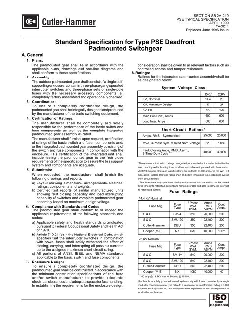
8. Ratings:<br />
Ratings <strong>for</strong> the integrated padmounted assembly shall be<br />
as designated below:<br />
System Voltage Class<br />
15KV 25KV<br />
KV, Nominal 14.4 25<br />
KV, Maximum Design 17 27<br />
KV, BIL 95 125<br />
Main Bus Cont., Amps 600 600<br />
Load Inter. Amps 600 600<br />
Short-Circuit Ratings*<br />
Amps, RMS Symmetrical 25,000 25,000<br />
MVA, 3-Phase Sym. at rated Nom. Voltage 620 1,080<br />
Fault Closing Amps, RMS, Asym.,<br />
3-Time Duty Cycle **<br />
40,000 40,000<br />
*These are nominal switch ratings. Integrated padmounted unit may be limited by the<br />
fuse, bushing wells, bushing inserts, elbow and cable ratings used with these units.<br />
Most 200 ampere elbow and insert systems are limited to 10,000 amperes rms sym (1.3<br />
max. asym. factor). Use fuse rating chart and elbow limitations to select proper overall<br />
short circuit ratings.<br />
**The three-time duty-cycle fault closing rating means that the switch can be closed<br />
three times into rated fault current and remain operable and able to carry and interrupt<br />
its rated load current.<br />
14.4 KV Nominal<br />
Fuse Mfg.<br />
Fuse Ratings<br />
Fuse<br />
<strong>Type</strong><br />
3-Phase<br />
MVA<br />
SYM.<br />
Amps<br />
RMS<br />
ASYM<br />
Cont.<br />
Amps.<br />
S & C SM-4 310 20,000 200<br />
S & C SMU-20 350 22,400 200<br />
Cutler-Hammer DBU 350 22,400 200<br />
Cooper (M-E) NX 620 40,000 100**<br />
25 KV Nominal<br />
Fuse Mfg.<br />
Fuse<br />
<strong>Type</strong><br />
3-Phase<br />
MVA<br />
SYM.<br />
Amps<br />
RMS<br />
ASYM<br />
Cont.<br />
Amps.<br />
S & C SM-4† 540 20,000 200<br />
S & C SMU-20 540 22,400 200<br />
Cutler-Hammer DBU 540 22,400 200<br />
Cooper (M-E) NX 1,080 40,000 40<br />
** 100 amp @ 13.5KV max. or 80 amp @ 15.5KV.<br />
†Applicable to solidly grounded neutral systems only with fuses connected by a single<br />
conductor concentric neutral type cable to a trans<strong>for</strong>mer or trans<strong>for</strong>mers. Rating is 9,400<br />
amperes RMS symmetrical, 15,000 amperes RMS asymmetrical, 405 MVA symmetrical<br />
<strong>for</strong> all other applications.<br />
ISO 9002<br />
Registered
SECTION SB-2A-210<br />
<strong>PSE</strong> TYPICAL SPECIFICATION<br />
APRIL 1999<br />
PAGE 2<br />
9. Insulators<br />
The interrupter switch and fuse mounting insulators<br />
shall have the following material characteristics and<br />
restrictions:<br />
a) Operating experience of at least 15 years under<br />
similar conditions.<br />
b) Ablative action to ensure non-tracking properties.<br />
c) Adequate leakage distance established by test per<br />
IEC Publication 507, First Edition, 1975.<br />
d) Adequate strength <strong>for</strong> short-circuit stress established<br />
by test.<br />
e) Con<strong>for</strong>mance with applicable ANSI standards.<br />
f) Homogeneity of the cycloaliphatic epoxy resin<br />
throughout each insulator to provide maximum<br />
resistance to power arcs. Ablation due to high<br />
temperature from power arcs shall continuously<br />
expose more material of the same composition and<br />
properties so that no change in mechanical or electrical<br />
characteristics takes place because of arc-induced<br />
ablation. Furthermore, any surface damage to<br />
insulators during installation or maintenance of the<br />
padmounted gear shall expose material of the same<br />
composition and properties so that insulators with<br />
minor surface damage need not be replaced.<br />
g) Each insulator shall be x-rayed to assure it is<br />
essentially void free. An alternate testing method<br />
may be used only by approval of the engineer.<br />
10. High Voltage Bus:<br />
Bus and interconnections shall consist of bare aluminum<br />
bar of 56% IACS conductivity with an oxide-inhibiting<br />
agent at all bus joints.<br />
Bus and interconnections shall withstand the stresses<br />
associated with short circuits up through the maximum<br />
rating of the padmounted gear, including proper allowance<br />
<strong>for</strong> transient conditions.<br />
Bolted aluminum-to-aluminum connections shall be made<br />
with a suitable number of non-corrosive bolts and with<br />
two Belleville spring washers per bolt, one under the bolt<br />
head and one under the nut. Bolts shall be tightened to an<br />
appropriate torque to assure good electrical connection.<br />
11. Ground Connection Pads:<br />
A ground connection pad shall be provided in each<br />
termination compartment of the padmounted gear.<br />
The ground connection pad shall be constructed of 1/4"<br />
thick, galvanized or stainless steel and have a NEMA 2hole<br />
pattern <strong>for</strong> ground connections. The pad shall be<br />
welded to the enclosure and shall have a short-circuit<br />
rating equal to that of the integrated assembly.<br />
A full width copper grounding rod shall be provided in<br />
each cable terminating compartment.<br />
B. Construction<br />
1. Enclosure:<br />
The padmounted enclosure shall be of unitized construction<br />
(not structural frame and bolted sheet) to maximize strength,<br />
minimize weight, and inhibit internal corrosion.<br />
The basic materials shall be 11 gauge hot rolled, pickled<br />
and oiled steel sheet. All structural joints and butt joints<br />
shall be welded, and the external seams shall be ground<br />
flush and smooth. A welding process shall be employed<br />
that eliminates alkaline residues and minimizes distortion<br />
and spatter.<br />
To guard against unauthorized or inadvertent entry,<br />
enclosure construction shall not utilize any externally<br />
accessible hardware.<br />
The base shall consist of continuous 90-degree flanges,<br />
turned inward and welded at the corners, <strong>for</strong> bolting to the<br />
concrete pad.<br />
The door openings shall have 90-degree flanges, facing<br />
outward, that shall provide strength and rigidity as well as<br />
deep overlapping between doors and door openings to<br />
guard against water entry.<br />
In consideration of tamper resistance, the enclosure shall<br />
con<strong>for</strong>m to or exceed the requirements of ANSI C57.12.28.<br />
A heavy coat of insulating "no-drip" compound shall be<br />
applied to the inside surface of the roof to reduce<br />
condensation of moisture thereon.<br />
Lifting tabs shall be removable. Sockets <strong>for</strong> the lifting tab<br />
bolts shall be blind-tapped. A protective material shall be<br />
placed between the lifting tabs and the enclosure to prevent<br />
the tabs from scratching the enclosure finish. This material<br />
shall be non-hygroscopic to prevent moisture from being<br />
absorbed.<br />
Optional:<br />
A steel (specify compartmented or noncompartmented)<br />
base spacer shall be provided to<br />
increase the elevation of live parts in the padmounted gear<br />
above the mounting pad by (specify 6, 12, 18, 24) inches.<br />
2. Barrier Assembly:<br />
Insulating interphase and end barriers shall be provided in<br />
each switch and fuse compartment. This barrier system<br />
shall be constructed of fiberglass rein<strong>for</strong>ced polyester<br />
(NEMA rated GPO-3).<br />
3. Doors:<br />
Doors shall be constructed of 11 gauge hot rolled, pickled<br />
and oiled steel sheet.<br />
Door edge flanges shall overlap with door opening flanges<br />
and shall be <strong>for</strong>med to create a mechanical maze that shall<br />
guard against water entry or discourage tampering or<br />
insertion of <strong>for</strong>eign objects.<br />
Doors shall have a minimum of three stainless steel hinges<br />
and hinge pins. The hinge pins shall be secured in place to<br />
guard against tampering.<br />
One active and one passive door shall be provided and in<br />
consideration of controlled access and tamper resistance,<br />
each active door shall be equipped with a positive-action<br />
three-point auto-latch mechanism and padlock hasp.<br />
Each active door shall be provided with a stainless steel<br />
door handle. The door handles shall be padlockable and<br />
shall incorporate a hood to protect the padlock shackle<br />
from tampering and access to the operating bolt. Each<br />
handle shall be provided with a recessed penta (hex<br />
optional) head bolt <strong>for</strong> additional security.<br />
Each passive door shall be independently secured to the<br />
enclosure and shall not require a tool <strong>for</strong> opening.<br />
Doors providing access to fuses shall have provisions to<br />
store spare expulsion type fuse units or refills.<br />
Each door shall be provided with a zinc plated, galvanized<br />
or stainless steel door holder located above the door<br />
opening. These holders shall be hidden from view when<br />
the door is closed, and it shall not be possible <strong>for</strong> the
holders to swing inside the enclosure.<br />
4. Finish<br />
Full coverage at joints and blind areas shall be achieved by<br />
processing enclosures independently of components such<br />
as doors and roofs be<strong>for</strong>e assembly into the unitized<br />
structures.<br />
All exterior seams shall be sanded or ground smooth <strong>for</strong><br />
neat appearances.<br />
To remove oils and dirt, and to <strong>for</strong>m a chemically and<br />
anodically neutral conversion coating to improve the finishto-metal<br />
bond, and to retard underfilm propagation of<br />
corrosion, all surfaces shall undergo a chemical cleaning<br />
and phosphatizing process be<strong>for</strong>e any protective coatings<br />
are applied.<br />
The finishing system shall be applied without sags or runs<br />
<strong>for</strong> a pleasing appearance.<br />
After the enclosure is completely assembled and the<br />
components (switches, bus, etc.) are installed, the finish<br />
shall be inspected <strong>for</strong> scuffs and scratches.<br />
Blemishes shall be carefully touched up by hand to restore<br />
the protective integrity of the finish.<br />
Unless otherwise specified, the color shall be Munsell No.<br />
7GY3.29/1.5, dark green.<br />
To insure that the finishing system is capable of resisting<br />
corrosion, the manufacturer shall provide on request,<br />
certification that representative test panels, protected by<br />
the manufacturer's finish system, have passed the following<br />
tests:<br />
a) Salt spray (relates to coastal environments and/or<br />
presence of snow-melting salts or fertilizers). Scribe to<br />
bare metal and test <strong>for</strong> 2000 hours in a 5% salt spray<br />
per ASTM B-117. Loss of adhesion from bare metal<br />
should not extend more than 1/8" from the scribe.<br />
Underfilm corrosion should not extend more than 1/16"<br />
from the scribe.<br />
b) Crosshatch adhesion (relates to adhesion after<br />
scratching of the finish). Scribe to bare metal a cross<br />
hatch pattern of 100 1/16" wide squares. Apply Scotch<br />
710 tape and rapidly remove. There should be 100%<br />
adhesion to the bare metal and between layers.<br />
c) Humidity (relates to environments with high humidity).<br />
Test of 1000 hours subject to 100% humidity at 45-50<br />
degrees C per ASTM D-2247. There should be no<br />
blisters.<br />
d) Impact (relates to transit and handling damage and<br />
abuse by the public). Impact the test panel with a 160<br />
in-lb. falling dart per ASTM D-2794. There should be no<br />
cracking or chipping of the paint on the impact side of<br />
the test panels.<br />
e) Oil resistance (relates to probable contact with mineral<br />
oil). Immerse two test panels in mineral oil <strong>for</strong> 3 days,<br />
one at room temperature and one at 100 degrees C<br />
(212 degrees F). There should be no apparent changes,<br />
such as color shifts, blisters, loss of hardness or<br />
streaking.<br />
f) Ultraviolet Accelerated Weathering Test (relates to<br />
exposure to sunlight and rainfall, loss of gloss, color<br />
fading and chalking). Continuous exposure to ultraviolet<br />
light <strong>for</strong> 500 hours per ASTM G-53 with a cycle of 4<br />
hours ultraviolet followed by 4 hours of condensation.<br />
Loss of gloss shall not exceed 50% of original per<br />
ASTM D523.<br />
g) Water Resistance (relates to rainfall or dew). Immerse<br />
a test panel in distilled water <strong>for</strong> 3 days at room<br />
SECTION SB-2A-210<br />
<strong>PSE</strong> TYPICAL SPECIFICATION<br />
APRIL 1999<br />
PAGE 3<br />
temperature. There should be no apparent changes,<br />
such as blistering, color shift, loss of hardness or<br />
streaking.<br />
h) Adhesion Fed. Spec 141A, Method 6301.1 (relates to<br />
adhesion after scratching the finish). Immerse test<br />
panel in distilled water <strong>for</strong> 24 hours. Make two parallel<br />
scratches 1" apart. Apply Scotch 710 tape and rapidly<br />
remove. There should be 100% adhesion to the bare<br />
metal and between layers.<br />
i) Abrasion Test - Taber Abrader (relates to wear<br />
encountered during installation). Prepare a panel coated<br />
with the component of the finish intended to provide<br />
abrasion resistance. Test using a CS-10 wheel, 1000<br />
gram weight, 3000 cycles, per Fed. Spec. 141, Method<br />
6192. This provides a comparative test between<br />
samples. To guard against corrosion, all hardware<br />
(including door fittings, fasteners, etc.), all operatingmechanism<br />
parts, and other parts subject to abrasive<br />
action from mechanical motion shall be of either<br />
nonferrous materials, or galvanized or zinc chromate<br />
plated ferrous materials. Cadmium-plated ferrous parts<br />
shall not be used.<br />
C. Construction<br />
1. Interrupter Switches:<br />
Interrupter switches shall have a three-time duty-cycle<br />
fault-closing rating equal to or exceeding the short circuit<br />
rating of the integrated padmounted gear assembly. These<br />
ratings define the ability to close the interrupter switch<br />
either alone (unfused) or in combination with the appropriate<br />
power fuses three times against a three-phase fault with<br />
asymmetrical current in at least one phase equal to the<br />
rated value, with the switch remaining operable and able to<br />
carry and interrupt rated current. Tests substantiating<br />
these ratings shall be per<strong>for</strong>med at maximum design<br />
voltage with current applied <strong>for</strong> at least 10 cycles. Certified<br />
test abstracts establishing such ratings shall be furnished<br />
upon request.<br />
Interrupter switches shall utilize a quick-make, quick-break<br />
mechanism installed by the switch manufacturer. The<br />
quick-make, quick-break mechanism shall be integrally<br />
mounted on the switch frame, and shall swiftly and positively<br />
open and close the interrupter switch independent of the<br />
speed of the switch operating handle.<br />
Interrupter switches shall be operated by means of an<br />
externally accessible switch-operating hub. The switchoperating<br />
hub shall be located within a recessed stainless<br />
steel pocket mounted on the side of the padmounted<br />
enclosure. The switch-operating hub pocket shall include<br />
a padlockable stainless steel access cover that shall<br />
incorporate a hood to protect the padlock shackle from<br />
tampering. Labels or targets to indicate switch positions<br />
shall be provided in the switch operating hub pocket.<br />
Each interrupter switch shall be completely assembled and<br />
adjusted by the switch manufacturer on a rigid mounting<br />
frame. The frame shall be of heavy gauge steel construction.<br />
Interrupter switch shall be provided with contact blades<br />
and interrupters <strong>for</strong> circuit closing, including fault closing,<br />
continuous current carrying, and circuit interrupting. Spring<br />
loaded auxiliary blades shall not be permitted.<br />
Circuit interruption shall be accomplished by use of an<br />
interrupter which is positively and inherently sequenced<br />
with the blade position. It shall not be possible <strong>for</strong> the blade<br />
and interrupter to get out of sequence.
SECTION SB-2A-210<br />
<strong>PSE</strong> TYPICAL SPECIFICATION<br />
APRIL 1999<br />
PAGE 4<br />
Interrupter switches shall have a readily visible open gap<br />
when in the open position to allow positive verification of<br />
correct switch position. In addition, an open/close label<br />
shall be provided to give a visual indicator of switch<br />
position.<br />
Each interrupter switch shall be provided with a switch<br />
operating handle. The switch-operating handle shall be<br />
secured to the inside of the switch operating hub pocket<br />
and shall be stored behind the switch operating hub access<br />
door.<br />
Optional:<br />
Key interlocks shall be provided to prevent paralleling the<br />
two source interrupter switches.<br />
Optional:<br />
Key interlocks shall be provided to guard against opening<br />
fuse compartment door(s) unless all switches (series tap<br />
switch only, where furnished) are locked open.<br />
Optional:<br />
Provision to padlock switch operating hub in open or<br />
closed position shall be provided.<br />
Optional:<br />
Cable guides shall be provided to help orient cables at<br />
switch and bus compartment terminals.<br />
Optional:<br />
Mounting provisions shall be provided to accommodate<br />
one three-phase fault indicator with three single-phase<br />
sensors in each switch compartment (except series tap<br />
switch, where furnished).<br />
2. Switch Compartments:<br />
Switch terminals shall be equipped with 600 ampere rated<br />
bushings that include removable threaded studs to<br />
accommodate a choice of termination systems. Fuse<br />
terminals are equipped with 200 ampere rated bushing<br />
wells designed to accept 200 ampere bushing inserts.<br />
Bushings and bushing wells have interfaces in accordance<br />
with ANSI/IEEE <strong>Standard</strong> 386 (ANSI <strong>Standard</strong> C119.2) to<br />
accept all standard separable insulated connectors and<br />
inserts. Parking stands are provided adjacent to each<br />
bushing and bushing well to accommodate feed-throughs<br />
and standoff insulators.<br />
All medium-voltage switch and fuse components are<br />
completely encased in an inner grounded steel<br />
compartment. The component compartment floor shall be<br />
of 18-gauge galvanized steel sheet to exclude foliage and<br />
animals.<br />
Viewing windows are provided within the termination<br />
compartments to allow visual verification of switch position,<br />
observation of switch-position open/close labels and<br />
inspection of blown-fuse indicators on power fuses.<br />
3. Fuse Compartment:<br />
Fuse access panels have a mechanical interlock that<br />
guards against gaining access to the fuse be<strong>for</strong>e opening<br />
the loadbreak separable insulated connector at the fuse<br />
terminal.<br />
The fuse shall be accessible only when de-energized and<br />
isolated — <strong>for</strong> full-view non-loadbreak disconnection and<br />
removal with a shotgun stick. This mounting features<br />
positive latching in both the energized and de-energized<br />
positions. When latched in the open position, the deenergized<br />
fuse is electrically isolated and readily accessible<br />
to operating personnel <strong>for</strong> removal.<br />
Access to the compartment containing energized switches<br />
or fuses shall be blocked by a latched GPO-3 panel.<br />
Individual ground rings are provided <strong>for</strong> each fuse mounting<br />
to allow convenient grounding of cable concentric neutrals<br />
and elbow accessories. These ground rings are also<br />
equipped with cable guides to assist in cable training and<br />
to prevent cables from interfering with movement of the<br />
fuse-access panel.<br />
To provide maximum service life and to prevent corrosion<br />
of moving parts, all latches and pivots in the fuse-handling<br />
mechanism are either painted steel, stainless steel, or<br />
zinc-plated.<br />
Optional:<br />
Fuse storage hooks shall be provided on switch-termination<br />
compartment access door(s). Each set of hooks shall<br />
allow the storing of three spare fuseholder or fuse units with<br />
end fittings <strong>for</strong> power fuses. Storage hooks shall be <strong>for</strong> two<br />
holders when current limiting fuses are used.<br />
D. Labeling:<br />
1. Warning Signs:<br />
All external doors shall be provided with NEMA approved<br />
"WARNING — HIGH VOLTAGE — KEEP OUT" signs.<br />
2. Rating Nameplates and Connection Diagrams:<br />
The outside of both the front and back shall be provided<br />
with nameplates indicating the manufacturer's name,<br />
catalog number, model number, and date of<br />
manufacture.<br />
The inside of each door shall be provided with a ratings<br />
label indicating the following: voltage ratings; main bus<br />
continuous rating; short-circuit ratings (amperes, RMS<br />
symmetrical and MVA three-phase symmetrical at rated<br />
nominal voltage); the type of fuse and its ratings including<br />
duty-cycle fault-closing capability; and interrupter switch<br />
ratings, including duty-cycle fault closing capability and<br />
amperes, short-time, RMS (momentary asymmetrical and<br />
one-second symmetrical).<br />
A three-line connection diagram showing interrupter<br />
switches, fuses and bus along with the manufacturer's<br />
model number shall be provided on the inside of both<br />
the front and rear doors, and on the inside of each switch<br />
operating hub access cover.<br />
E. Auxiliaries:<br />
End fittings or holders, and fuse units or refill units <strong>for</strong><br />
original installation, as well as spare fuse unit or refill unit<br />
<strong>for</strong> each fuse mounting, shall be furnished in accordance<br />
with the client's requirements when specified.


