Static and Dynamic Draft in HYPACK.fm
Static and Dynamic Draft in HYPACK.fm
Static and Dynamic Draft in HYPACK.fm

Create successful ePaper yourself
Turn your PDF publications into a flip-book with our unique Google optimized e-Paper software.
Treatments of <strong>Static</strong> <strong>and</strong> <strong>Dynamic</strong> <strong>Draft</strong> <strong>in</strong><br />
<strong>HYPACK</strong>®<br />
By Pat S<strong>and</strong>ers<br />
The follow<strong>in</strong>g document illustrates the different methodologies for treatment of the <strong>Static</strong> <strong>and</strong><br />
<strong>Dynamic</strong> <strong>Draft</strong> <strong>in</strong>side of <strong>HYPACK</strong>®.<br />
STATIC DRAFT<br />
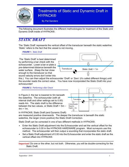
The ‘<strong>Static</strong> <strong>Draft</strong>’ represents the vertical offset of the transducer beneath the static waterl<strong>in</strong>e.<br />
‘<strong>Static</strong>’ refers to the fact that the vessel is not mov<strong>in</strong>g.<br />
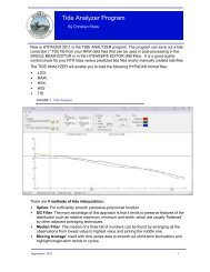
FIGURE 1. <strong>Static</strong> <strong>Draft</strong><br />
The ‘<strong>Static</strong> <strong>Draft</strong>’ is best determ<strong>in</strong>ed<br />
by perform<strong>in</strong>g a bar check with the<br />
echosounder. Lower a bar or plate a<br />
pre-determ<strong>in</strong>ed distance beneath the<br />
water surface. (Keep the bar close<br />
enough to the transducer so that<br />
sound velocity errors don’t enter <strong>in</strong>to<br />
this.) You can then adjust the echosounder ‘<strong>Draft</strong>’ or ‘Zero’ (it’s called different th<strong>in</strong>gs) until<br />
the sounder reads the correct value. You have now <strong>in</strong>corporated the <strong>Static</strong> <strong>Draft</strong> <strong>in</strong>to your<br />
echosounder!<br />
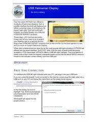
FIGURE 2. Perform<strong>in</strong>g a Bar Check<br />
In Figure 2, the bar is lowered to 5m beneath<br />
the waterl<strong>in</strong>e. The echosounder (with all<br />
<strong>in</strong>ternal draft <strong>and</strong> other sett<strong>in</strong>gs set to 0.00)<br />
reads 4m. The static draft is the difference<br />
between the two values, or <strong>Static</strong> <strong>Draft</strong> = 5m –<br />
4m = 1m.<br />
In <strong>HYPACK</strong>®, <strong>Static</strong> <strong>Draft</strong> (<strong>and</strong> <strong>Dynamic</strong> <strong>Draft</strong>)<br />
are measured positive downwards. The deeper the transducer is beneath the static<br />
waterl<strong>in</strong>e, the larger (more positive) the <strong>Static</strong> <strong>Draft</strong> Correction.<br />
<strong>Static</strong> <strong>Draft</strong> can be corrected <strong>in</strong> one of two different methods <strong>in</strong> <strong>HYPACK</strong>®.<br />
• Enter the <strong>Static</strong> <strong>Draft</strong> adjustment <strong>in</strong>to the Echosounder <strong>and</strong> set the vertical offset for the<br />
echosounder to 0.00 <strong>in</strong> the <strong>HYPACK</strong>® HARDWARE program. Most surveyors use this<br />
method. The echosounder will then output a sound<strong>in</strong>g that <strong>in</strong>corporates the static draft.<br />
• Set a <strong>Static</strong> <strong>Draft</strong> adjustment of 0.00 <strong>in</strong>to the Echosounder <strong>and</strong> enter the static draft as the<br />
vertical offset <strong>in</strong>to <strong>HYPACK</strong>®.<br />
Important! Do one or the other, but not both. Otherwise, you will be double-correct<strong>in</strong>g for the<br />
<strong>Static</strong> <strong>Draft</strong>.<br />
September / 2010 1
Let’s take a look at both methods:<br />
EXAM PLE 1: STATIC D RAFT IS INCORPORATED IN T O TH E<br />
2<br />
ECHOSOUNDER<br />
In this example, our bar check shows the <strong>Static</strong> <strong>Draft</strong> to be 1.0m. The <strong>Static</strong> <strong>Draft</strong> will be<br />
<strong>in</strong>corporated directly <strong>in</strong>to the echosounder, so that when the transducer is 19m above the<br />
bottom, the echosounder will report a depth of 20m.<br />
S<strong>in</strong>ce the echosounder is tak<strong>in</strong>g care of the <strong>Static</strong> <strong>Draft</strong>, <strong>HYPACK</strong>® does not need to correct<br />
for it. The vertical offset for your echosounder <strong>in</strong> the <strong>HYPACK</strong>® HARDWARE program<br />
should be set to 0.0.<br />
FIGURE 3. Incorporat<strong>in</strong>g <strong>Static</strong> <strong>Draft</strong> <strong>in</strong>to the Echosounder<br />
IN <strong>HYPACK</strong>® HARDWARE<br />
FIGURE 4. Offsets are Zero when <strong>Static</strong> <strong>Draft</strong> is <strong>in</strong> the Echosounder<br />
For your echosounder device, we will set the Vertical Offset to<br />
0.00m The Vertical Offset is where we would enter the <strong>Static</strong><br />
<strong>Draft</strong> of your echosounder if we did not correct for it directly <strong>in</strong> the<br />
echosounder.
IN SU RVEY<br />
In the <strong>HYPACK</strong>® SURVEY program, the ‘<strong>Draft</strong>’ displayed <strong>in</strong> the Data Display w<strong>in</strong>dow is the<br />
<strong>Dynamic</strong> <strong>Draft</strong> <strong>and</strong> will be 0.00. The depth reported from the echosounder will be 20.00. The<br />
corrected depth will be 20.00.<br />
IN TH E RAW D ATA FILE<br />
In the header, the INF record shows the Initial <strong>Dynamic</strong> <strong>Draft</strong> correction (second value from<br />
end) to be 0.00. There are no DFT (<strong>Draft</strong> records) <strong>in</strong> the body of the file, as the user has not<br />
changed the <strong>Dynamic</strong> <strong>Draft</strong> (we’re ignor<strong>in</strong>g it <strong>in</strong> the first two examples…)<br />
INF "Pat S<strong>and</strong>ers0" "RV 103" "Sample_Survey_A" "Savannah River"<br />
0.000000 0.000000 1529.000000<br />
The vertical offset for the Echosounder, shown <strong>in</strong> the 2 nd l<strong>in</strong>e (below) shows the 0.00m<br />
sett<strong>in</strong>g.<br />
DEV 0 16 "Echosounder" 0 C:\<strong>HYPACK</strong> 2010\devices\sim32.dll 9.0.3.5<br />
OFF 0 0.000000 0.000000 0.000000 0.000000 0.000000 0.000000 0.000000<br />
There are no DFT records, as we did not change the <strong>Dynamic</strong> <strong>Draft</strong> Correction while ON-<br />
LINE.<br />
IN TH E SIN G LE BEAM ED ITO R<br />
The Read Parameters show the Vertical Offset for the Echosounder was set to 0.00.<br />
FIGURE 5. Offsets as Recorded <strong>in</strong> SURVEY<br />
In the Spreadsheet w<strong>in</strong>dow (Figure 6), the Raw Depth com<strong>in</strong>g from the Echosounder is<br />
20.00m This results because the echosounder has already comb<strong>in</strong>ed the Depth Below<br />
Transducer (19.00m) with the <strong>Static</strong> <strong>Draft</strong> correction (1.00m) <strong>in</strong>corporated directly <strong>in</strong>to the<br />
Echosounder. The sounder outputs a depth of 20.00m, which is what the SURVEY program<br />
reads.<br />
S<strong>in</strong>ce there is no <strong>Dynamic</strong> <strong>Draft</strong> correction <strong>in</strong> this example <strong>and</strong> s<strong>in</strong>ce the <strong>Static</strong> <strong>Draft</strong><br />
correction is be<strong>in</strong>g taken care of <strong>in</strong> the echosounder, the <strong>Draft</strong> Correction column <strong>in</strong> the<br />
SINGLE BEAM EDITOR shows 0.00m. The f<strong>in</strong>al Corrected Depth shows 20.00m, which is<br />
correct!<br />
September / 2010 3
4<br />
FIGURE 6. <strong>Static</strong> <strong>Draft</strong> <strong>in</strong> the Sounder <strong>and</strong> No <strong>Dynamic</strong> <strong>Draft</strong> - <strong>Draft</strong> Correction Appears as Zero<br />
EXAM PLE 2: STATIC D RAFT IS INCORPORATED IN <strong>HYPACK</strong>®<br />
In this example (Figure 7), we have once aga<strong>in</strong> determ<strong>in</strong>ed the <strong>Static</strong> <strong>Draft</strong> to be 1.0m. We<br />
will not <strong>in</strong>corporate the <strong>Static</strong> <strong>Draft</strong> <strong>in</strong> the echosounder, so that it will report the Depth Below<br />
Transducer, which is 19m. To account for the <strong>Static</strong> <strong>Draft</strong> <strong>in</strong> this example, we will set the<br />
Vertical Offset for the echosounder to 1.0m <strong>in</strong> the <strong>HYPACK</strong>® HARDWARE program.<br />
FIGURE 7. <strong>Static</strong> <strong>Draft</strong> <strong>in</strong> <strong>HYPACK</strong>®
IN <strong>HYPACK</strong>® H ARD W ARE<br />
FIGURE 8. <strong>Draft</strong> Entered as Vertical Offset of the Echosounder<br />
We’ll set the Vertical Offset for the echosounder equal to our <strong>Static</strong> <strong>Draft</strong> correction of 1.0m.<br />
Remember that the vertical offsets are ‘Positive Downwards’. You should never have a<br />
vertical offset for your echosounder, unless it is somehow above the static waterl<strong>in</strong>e.<br />
IN SU RVEY<br />
FIGURE 9. Depth Calculations Include the Echosounder’s Vertical Offset<br />
In the <strong>HYPACK</strong>® SURVEY program’s Data Display w<strong>in</strong>dow, the <strong>Static</strong> <strong>Draft</strong> (Vertical Offset)<br />
is added to the Raw Sound<strong>in</strong>g reported by the echosounder. In our case, SURVEY<br />
comb<strong>in</strong>es the 1.0m Vertical Offset with the 19.0m reported by the echosounder <strong>and</strong> displays<br />
Depth = 20.0, <strong>Draft</strong> = 0.00 <strong>and</strong> Corrected Depth = 20.0. The <strong>Dynamic</strong> <strong>Draft</strong> (<strong>Draft</strong>/Squat<br />
Corr.) is 0.00m <strong>in</strong> this example.<br />
IN TH E RAW D ATA FILE<br />
In the header, the INF record shows an Initial <strong>Dynamic</strong> <strong>Draft</strong> value of 0.00.<br />
INF "Pat S<strong>and</strong>ers0" "RV 103" "Sample_Survey_A" "Savannah River"<br />
0.000000 0.000000 1529.000000<br />
Also <strong>in</strong> the header, the device record for the Echosounder has a vertical offset (<strong>Static</strong> <strong>Draft</strong>)<br />
of 1.00m<br />
DEV 0 16 "Echosounder" 0 C:\<strong>HYPACK</strong> 2010\devices\sim32.dll 9.0.3.5<br />
OFF 0 0.000000 0.000000 1.000000 0.000000 0.000000 0.000000 0.000000<br />
In the body of the file, the EC1 records show the Raw Depth received from the Echosounder<br />
as 19.00<br />
EC1 0 41193.724 19.000<br />
EC1 0 41193.927 19.000<br />
September / 2010 5
EC1 0 41194.130 19.000<br />
There are no DFT records <strong>in</strong> the body of the file, as we haven’t made any changes to the<br />
draft sett<strong>in</strong>gs while the program is “ON LINE”.<br />
IN TH E SIN G LE BEAM ED ITO R<br />
The Read Parameters show the Vertical Offset for the Echosounder is 1.0m.<br />
6<br />
FIGURE 10. Sounder’s Vertical Offset = 0<br />
In the Spreadsheet w<strong>in</strong>dow, the Raw Depth reported by the echosounder is the Depth Below<br />
Transducer, which is 19.00m. The <strong>Static</strong> <strong>Draft</strong> (Vertical Offset) is shown <strong>in</strong> the <strong>Draft</strong><br />
Correction column as 1.00m. The Corrected Depth is shown as 20.00m, which is correct!<br />
FIGURE 11. Sounder’s Vertical Offset Shows as a <strong>Draft</strong> Correction <strong>in</strong> the SINGLE BEAM EDITOR<br />
DYNAMIC DRAFT<br />
‘<strong>Dynamic</strong> <strong>Draft</strong>’ represents the vertical movement of the echosounder transducer as the<br />
vessel is underway. There are two components to <strong>Dynamic</strong> <strong>Draft</strong>:<br />
• Squat: As you apply power to the back end of the vessel, the front end moves upward<br />
<strong>and</strong> the back end moves downward. Depend<strong>in</strong>g where your transducer is mounted, this<br />
can result <strong>in</strong> either an <strong>in</strong>crease or a decrease <strong>in</strong> the depth reported by the echosounder.<br />
• Settlement: Due to the hydrodynamic effects of the vessel mov<strong>in</strong>g through the water, a<br />
pressure wave can form <strong>in</strong> advance of the vessel, result<strong>in</strong>g <strong>in</strong> water ‘stack<strong>in</strong>g up’ <strong>in</strong> front
of the vessel. The water <strong>in</strong> the stack can come from the water surround<strong>in</strong>g the vessel,<br />
result<strong>in</strong>g <strong>in</strong> a downward displacement of the vessel.<br />
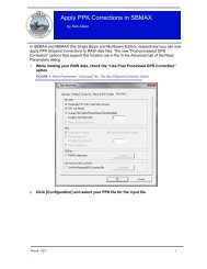
FIGURE 12. <strong>Static</strong> <strong>Draft</strong> (left) vs <strong>Dynamic</strong> <strong>Draft</strong> (right)<br />
In Figure 12, the vessel on the left is ‘<strong>Static</strong>’ (not mov<strong>in</strong>g). We have determ<strong>in</strong>ed the <strong>Static</strong><br />
<strong>Draft</strong> is 1.0 m <strong>and</strong> the Depth Below Transducer is 19.0m. The same vessel on the right is<br />
underway <strong>and</strong> the transducer has descended 0.5m <strong>in</strong> the water column. The <strong>Static</strong> <strong>Draft</strong> is<br />
still 1.0m, the <strong>Dynamic</strong> <strong>Draft</strong> is 0.5m <strong>and</strong> the Depth Below Transducer is now 18.5. We’ll use<br />
these sett<strong>in</strong>gs <strong>in</strong> the next examples.<br />
In <strong>HYPACK</strong>®, F<strong>in</strong>al Depth = Raw Depth + <strong>Static</strong> <strong>Draft</strong> + <strong>Dynamic</strong> <strong>Draft</strong> (+ Tide, SV <strong>and</strong><br />
Heave corrections)<br />
• In the <strong>Static</strong> Case: F<strong>in</strong>al Depth = 19.0 + (1.0 + 0.0) = 20.0<br />
• In the <strong>Dynamic</strong> Case: F<strong>in</strong>al Depth = 18.5 + (1.0 + 0.5) = 20.0<br />
H OW TO D ETERM IN E TH E D YN AM IC D RAFT FO R YO U R<br />
SURVEY BOAT<br />
There are two practical methods for determ<strong>in</strong><strong>in</strong>g the <strong>Dynamic</strong> <strong>Draft</strong> for your vessel. Before<br />
mak<strong>in</strong>g that determ<strong>in</strong>ation, you should first correct for the <strong>Static</strong> <strong>Draft</strong>, by perform<strong>in</strong>g a bar<br />
check. You should also perform these measurements at slack tide, or make a note of the<br />
changes <strong>in</strong> the water level so they can be factored out of your test. We will need to determ<strong>in</strong>e<br />
the <strong>Dynamic</strong> <strong>Draft</strong> correction over a range of eng<strong>in</strong>e power sett<strong>in</strong>gs, as the correction can<br />
vary due to amount of power be<strong>in</strong>g applied.<br />
• Method 1: Use a Level Instrument.<br />
a. Set up a level <strong>in</strong>strument on the end of a pier.<br />
b. Have a crew member hold a stadia rod vertically above the transducer.<br />
c. Have the level operator make read<strong>in</strong>gs when the vessel is static <strong>and</strong> underway at<br />
different power sett<strong>in</strong>gs.<br />
Note: Try to make the read<strong>in</strong>g when the vessel is the same distance from the level<br />
<strong>in</strong>strument.<br />
September / 2010 7
d. You can then compare the level read<strong>in</strong>gs <strong>and</strong> create a table that has the <strong>Dynamic</strong><br />
<strong>Draft</strong> correction for different power sett<strong>in</strong>gs.<br />
e. Use your GPS to determ<strong>in</strong>e the speed over ground for each power sett<strong>in</strong>g.<br />
• Method 2: Run Survey L<strong>in</strong>es over a Flat Area at Different Power Sett<strong>in</strong>gs.<br />
To use this method, you need to f<strong>in</strong>d a survey area where the bottom is relatively flat.<br />
a. Create a survey l<strong>in</strong>e through the flat area.<br />
b. With the vessel <strong>in</strong> static mode (no power be<strong>in</strong>g applied), try to get some depth<br />
samples along the l<strong>in</strong>e.<br />
c. run the survey l<strong>in</strong>e at different power sett<strong>in</strong>gs, sav<strong>in</strong>g each run to a separate data file.<br />
d. Process the data files <strong>in</strong> the SINGLE BEAM EDITOR (apply<strong>in</strong>g tide corrections)<br />
e. display the files <strong>in</strong> the CROSS SECTIONS AND VOLUMES program. Determ<strong>in</strong>e the<br />
vertical difference <strong>in</strong> each profile as a function of the power applied <strong>and</strong> create a table<br />
of the sett<strong>in</strong>gs.<br />
The results of our test may look like Table 1:<br />
8<br />
TABLE 1. <strong>Dynamic</strong> <strong>Draft</strong> vs Speed<br />
Power<br />
<strong>Dynamic</strong> <strong>Draft</strong><br />
Correction Speed (SOG)<br />
None 0.0 0.0<br />
Idle (Slow Ahead) 0.25 0.5 kts<br />
First Notch 0.40 4.5 kts<br />
Second Notch (Survey Speed) 0.60 8.0 kts<br />
APPLYIN G D YN AM IC D RAFT IN SU RVEY<br />
To apply the dynamic draft sett<strong>in</strong>gs <strong>in</strong> SURVEY, you can either manually enter the sett<strong>in</strong>gs as<br />
the power changes, or use the DRAFTTABLE driver to automatically adjust the dynamic draft<br />
based upon the speed of the vessel.<br />
• Method 1: Manually Adjust<strong>in</strong>g the <strong>Draft</strong>.<br />
In SURVEY, you can manually change the <strong>Dynamic</strong> <strong>Draft</strong> at any time by click<strong>in</strong>g on the<br />
Vessel menu <strong>and</strong> manually enter<strong>in</strong>g the new value. The program will then write a DFT<br />
record <strong>in</strong> the data file at the time of change (if you are “ON LINE”) <strong>and</strong> also write the<br />
current sett<strong>in</strong>g anytime you Start L<strong>in</strong>e. In the latest version of SURVEY, the w<strong>in</strong>dow looks<br />
like the follow<strong>in</strong>g:<br />
FIGURE 13. Enter<strong>in</strong>g <strong>Draft</strong> <strong>in</strong> the Vessel Dialog
If you have multiple vessels, you should make sure you highlight the appropriate vessel <strong>in</strong> the<br />
top-left list box.<br />
• Method 2: Us<strong>in</strong>g the DRAFTTABLE.DLL:<br />
The DRAFTTABLE.DLL allows you to construct a table of <strong>Dynamic</strong> <strong>Draft</strong> Correction<br />
versus Speed. The driver then uses the Speed Over Ground from the GPS (or the<br />
<strong>in</strong>ternal speed computed by SURVEY) <strong>and</strong> <strong>in</strong>terpolates a draft correction based on the<br />
Speed Over Ground.<br />
Note On a river, your speed through the water column may not equal your speed over<br />
ground. This could cause some significant errors <strong>in</strong> the <strong>Dynamic</strong> <strong>Draft</strong> correction<br />
be<strong>in</strong>g assigned by the driver.<br />
FIGURE 14. Configur<strong>in</strong>g the <strong>Draft</strong>Table Driver<br />
This driver is actually capable of comput<strong>in</strong>g both a shallow water <strong>and</strong> a deeper water<br />
correction. The German Hydrographic Office demonstrated <strong>in</strong> a technical paper several<br />
years ago that their 8m survey vessels experienced a 15cm difference <strong>in</strong> the dynamic draft<br />
depend<strong>in</strong>g on whether the vessel was operat<strong>in</strong>g <strong>in</strong> shallow water (less than 4m) or deeper<br />
water (greater than 8m). This was due to the limitation of the hydrodynamic forces that<br />
contribute to the Settlement of the vessel <strong>in</strong> shallow water compared to deeper water. Most<br />
of our surveyors only use a s<strong>in</strong>gle correction curve <strong>and</strong> the driver can be set up for that by<br />
disabl<strong>in</strong>g the checkbox <strong>in</strong> the Dual <strong>Draft</strong> Correction box.<br />
When configur<strong>in</strong>g this device driver <strong>in</strong> <strong>HYPACK</strong>® HARDWARE, you should limit the update<br />
rate (use the Advanced Tab for the driver). You don’t need to have 20 DFT records per<br />
second. I would recommend you limit the update rate of the driver to 1000mSec (1 second).<br />
September / 2010 9
EXAM PLE 3: STATIC D RAFT IS INCORPORATED IN<br />
ECHOSOUNDER AN D D YN AM IC D RAFT IS M AN UALLY<br />
10<br />
EN TERED<br />
In this example, the bottom is 20m beneath the static waterl<strong>in</strong>e. We have determ<strong>in</strong>ed a <strong>Static</strong><br />
<strong>Draft</strong> correction of 1.0m <strong>and</strong> it has been <strong>in</strong>corporated <strong>in</strong>to the echosounder. S<strong>in</strong>ce we are<br />
work<strong>in</strong>g on a river, we are go<strong>in</strong>g to manually enter a <strong>Dynamic</strong> <strong>Draft</strong> correction of 0.5m, which<br />
we have determ<strong>in</strong>ed is our correction at normal survey speed. The echosounder reports a<br />
depth of 19.5m.<br />
FIGURE 15. <strong>Static</strong> <strong>Draft</strong> <strong>in</strong> the Sounder <strong>and</strong> Manual <strong>Dynamic</strong> <strong>Draft</strong><br />
IN <strong>HYPACK</strong>® HARDWARE<br />
FIGURE 16. Vertical Offset for the Echosounder is Zero<br />
For the Echosounder device, we have already entered the <strong>Static</strong><br />
<strong>Draft</strong> correction <strong>in</strong>to the echosounder. The Vertical Offset (<strong>Static</strong><br />
<strong>Draft</strong>) for the Echosounder <strong>in</strong> <strong>HYPACK</strong>® HARDWARE should be<br />
set to 0.0.
IN SU RVEY<br />
FIGURE 17. Manually Enter<strong>in</strong>g <strong>Draft</strong> <strong>in</strong> the Vessels Dialog<br />
We need to go <strong>in</strong>to the ‘Vessel’ menu <strong>and</strong> set the <strong>Draft</strong> for our Survey vessel to 0.5.<br />
IN TH E D ATA D ISPLA Y W IN D O W<br />
FIGURE 18. The <strong>Draft</strong> Correction is reported <strong>in</strong> the Data<br />
Display<br />
The Depth is displayed as 19.50m. SURVEY takes<br />
the depth received from the echosounder (19.50m)<br />
<strong>and</strong> adds any Vertical Offset (0.00m) from the<br />
device driver. The <strong>Draft</strong> correction is shown as<br />
0.50m (our manual sett<strong>in</strong>g) <strong>and</strong> the Correct Depth<br />
is shown as 20.00m<br />
IN TH E RAW D ATA FILE<br />
The INF record at the top of the file shows an <strong>in</strong>itial <strong>Dynamic</strong> <strong>Draft</strong> Correction as 0.50m. This<br />
is because we manually set the correction to 0.50m before start<strong>in</strong>g the l<strong>in</strong>e.<br />
INF "Pat S<strong>and</strong>ers0" "RV 103" "Sample_Survey_A" "Savannah River"<br />
0.000000 0.500000 1529.000000<br />
The vertical offset for the Echosounder shows the 0.00m sett<strong>in</strong>g.<br />
DEV 0 16 "Echosounder" 0 C:\<strong>HYPACK</strong> 2010\devices\sim32.dll 9.0.3.5<br />
OFF 0 0.000000 0.000000 0.000000 0.000000 0.000000 0.000000 0.000000<br />
There are no DFT records, as we did not change the <strong>Draft</strong> Correction Value while ON-LINE.<br />
The EC1 (S<strong>in</strong>gle Beam Echosounder) records show a value of 19.5 be<strong>in</strong>g received from the<br />
sounder. Remember, we <strong>in</strong>corporate the <strong>Static</strong> <strong>Draft</strong> (1.0m) <strong>in</strong>to the echosounder. The<br />
echosounder adds the <strong>Static</strong> <strong>Draft</strong> to the Depth Below Transducer (18.5m) <strong>and</strong> outputs a<br />
depth of 19.5m to the computer.<br />
EC1 0 45275.192 19.500<br />
EC1 0 45275.395 19.500<br />
EC1 0 45275.599 19.500<br />
September / 2010 11
IN TH E SIN G LE BEAM ED ITO R<br />
12<br />
FIGURE 19. Manually Entered <strong>Draft</strong> Corrections Displayed Under <strong>Draft</strong> Corr<br />
The Vertical Offset for the Echosounder is displayed as 0.00m <strong>in</strong> the Read Parameters –<br />
Offsets w<strong>in</strong>dow. In the Spreadsheet w<strong>in</strong>dow, the Raw Depth is displayed as 19.50m. The<br />
<strong>Static</strong> <strong>Draft</strong> correction has been <strong>in</strong>corporated <strong>in</strong>to the Raw Depth by the echosounder. The<br />
<strong>Draft</strong> correction represents the <strong>Dynamic</strong> <strong>Draft</strong> correction <strong>and</strong> is displayed as 0.50m. Our f<strong>in</strong>al<br />
Corrected Depth is displayed as 20.00m <strong>and</strong> is correct.<br />
EXAM PLE 4: STATIC D RAFT IS EN TERED IN <strong>HYPACK</strong>® AN D<br />
D YN AM IC D RAFT IS M AN U ALLY EN TERED<br />
In this example, the bottom is 20m beneath the static waterl<strong>in</strong>e. We have determ<strong>in</strong>ed the<br />
<strong>Static</strong> <strong>Draft</strong> Correction is 1.0m. The echosounder is set up to output the Depth Below<br />
Transducer, so we will enter the <strong>Static</strong> <strong>Draft</strong> as our Vertical Offset of the Echosounder <strong>in</strong><br />
<strong>HYPACK</strong>® HARDWARE. As <strong>in</strong> the previous example, we are go<strong>in</strong>g to manually enter the<br />
<strong>Dynamic</strong> <strong>Draft</strong> of 0.5m.
FIGURE 20. <strong>Static</strong> <strong>Draft</strong> as a Vertical Offset, Manual <strong>Dynamic</strong> <strong>Draft</strong><br />
IN <strong>HYPACK</strong>® H ARD W ARE<br />
S<strong>in</strong>ce we are correct<strong>in</strong>g for the <strong>Static</strong> <strong>Draft</strong> <strong>in</strong> <strong>HYPACK</strong>®, we will enter the <strong>Static</strong> <strong>Draft</strong> (1.0m)<br />
as the Vertical Offset for the Echosounder <strong>in</strong> <strong>HYPACK</strong>® HARDWARE.<br />
FIGURE 21. Enter<strong>in</strong>g <strong>Static</strong> <strong>Draft</strong> as a Vertical Offset of the Sounder<br />
IN SU RVEY<br />
Once aga<strong>in</strong>, s<strong>in</strong>ce we are manually enter<strong>in</strong>g the <strong>Dynamic</strong> <strong>Draft</strong>,<br />
we need to go to the ‘Vessel’ menu <strong>and</strong> set it for 0.50m.<br />
(SURVEY should remember your previous sett<strong>in</strong>g.)<br />
FIGURE 22. Enter<strong>in</strong>g <strong>Dynamic</strong> <strong>Draft</strong> <strong>in</strong> the Vessels Dialog<br />
In the Data Display W<strong>in</strong>dow, SURVEY comb<strong>in</strong>es the Raw Depth reported by the<br />
echosounder (18.5m) with the <strong>Static</strong> <strong>Draft</strong> (Vertical Offset = 1.00m) <strong>and</strong> shows a Depth =<br />
19.50m. The <strong>Dynamic</strong> <strong>Draft</strong> is shown as 0.50m <strong>and</strong> the F<strong>in</strong>al Corrected Depth is shown as<br />
20.00m, which is correct!<br />
September / 2010 13
14<br />
FIGURE 23. Survey Reports Depth that Includes <strong>Static</strong> <strong>Draft</strong>, <strong>Draft</strong> Correction Equal to <strong>Dynamic</strong> <strong>Draft</strong><br />
IN TH E RAW D ATA FILE<br />
The INF record near the top of the header shows an <strong>in</strong>itial <strong>Dynamic</strong> <strong>Draft</strong> correction of 0.50.<br />
This is because we manually set the correction before start<strong>in</strong>g the survey l<strong>in</strong>e.<br />
INF "Pat S<strong>and</strong>ers0" "RV 103" "Sample_Survey_A" "Savannah River"<br />
0.000000 0.500000 1529.000000<br />
The Device record <strong>in</strong> the header shows a Vertical Offset of 1.00m for the Echosounder<br />
device. This is our <strong>Static</strong> <strong>Draft</strong> value that we entered as the Vertical Offset for the<br />
echosounder driver.<br />
DEV 0 16 "Echosounder" 0 C:\<strong>HYPACK</strong> 2010\devices\sim32.dll 9.0.3.5<br />
OFF 0 0.000000 0.000000 1.000000 0.000000 0.000000 0.000000 0.000000<br />
The S<strong>in</strong>gle Beam Echosounder records (EC1) show a depth received from the sounder of<br />
18.50.<br />
Note Although the depth reported by the echosounder <strong>and</strong> the <strong>Static</strong> <strong>Draft</strong> are comb<strong>in</strong>ed for<br />
display <strong>in</strong> the Data Display w<strong>in</strong>dow, they are ma<strong>in</strong>ta<strong>in</strong>ed as separate entities <strong>in</strong> the<br />
RAW data file.<br />
EC1 0 48142.276 18.500<br />
EC1 0 48142.479 18.500<br />
EC1 0 48142.682 18.500<br />
IN TH E SIN G LE BEAM ED ITO R<br />
The Vertical Offset (<strong>Static</strong> <strong>Draft</strong>) is displayed as 1.00m <strong>in</strong> the Read Parameters – Offsets<br />
w<strong>in</strong>dow.
FIGURE 24. <strong>Static</strong> <strong>and</strong> <strong>Dynamic</strong> <strong>Draft</strong> Corrections Comb<strong>in</strong>e to Display as 1.5.<br />
In the Spreadsheet w<strong>in</strong>dow, the Raw Depth is displayed as 18.50m. The <strong>Draft</strong> Correction<br />
now comb<strong>in</strong>es both the <strong>Static</strong> <strong>Draft</strong> (Vertical Offset = 1.0m) <strong>and</strong> the <strong>Dynamic</strong> <strong>Draft</strong> value<br />
(0.50) <strong>and</strong> displays a <strong>Draft</strong> Correction of 1.50m. The Corrected Depth shows 20.00m, which<br />
is correct.<br />
Note: It is important to note that the SINGLE BEAM EDITOR comb<strong>in</strong>es the <strong>Static</strong> <strong>and</strong><br />
<strong>Dynamic</strong> <strong>Draft</strong> values <strong>in</strong>to a s<strong>in</strong>gle <strong>Draft</strong> Correction component. In future versions, we<br />
hope to keep the two corrections as separate entities.<br />
EXAM PLE 5: STATIC D RAFT IS INCORPORATED IN<br />
ECHOSOUNDER AN D D YN AM IC D RAFT COM ES FRO M<br />
D RAFTTABLE<br />
This example is similar to Example 3, except that <strong>in</strong>stead of manually enter<strong>in</strong>g the <strong>Dynamic</strong><br />
<strong>Draft</strong> correction, we will be us<strong>in</strong>g the DRAFTTABLE.DLL to assign the correction based upon<br />
the vessel’s speed over ground.<br />
The echosounder has the <strong>Static</strong> <strong>Draft</strong> (1.0m) set <strong>in</strong>to it <strong>and</strong> will report a Depth = 19.5m. The<br />
<strong>Dynamic</strong> <strong>Draft</strong> at our survey speed (5kts) is determ<strong>in</strong>ed to be 0.5m.<br />
September / 2010 15
16<br />
FIGURE 25. <strong>Static</strong> <strong>Draft</strong> is Incorporated <strong>in</strong>to the Echosounder, <strong>Dynamic</strong> <strong>Draft</strong> Fro the <strong>Draft</strong>Table.dll<br />
IN <strong>HYPACK</strong>® HARDWARE<br />
• For the Echosounder: S<strong>in</strong>ce the <strong>Static</strong> <strong>Draft</strong> (1.0m) is <strong>in</strong>corporated directly <strong>in</strong>to the<br />
echosounder. We will set the Vertical Offset for the echosounder to 0.00m.<br />
FIGURE 26. <strong>Static</strong> <strong>Draft</strong> is <strong>in</strong> the Sounder so its Veritical Offset is Zero<br />
• For the DRAFTTABLE.DLL: There are no offsets associated with the<br />
DRAFTTABLE.DLL. After select<strong>in</strong>g the driver, click the Setup button to access the table<br />
entries <strong>and</strong> driver sett<strong>in</strong>gs.
FIGURE 27. <strong>Draft</strong>Table Driver Setup<br />
My sett<strong>in</strong>gs (Figure 27) show that at 5kts, we should have an <strong>in</strong>terpolated <strong>Dynamic</strong> <strong>Draft</strong><br />
value of 0.5m. I have elected to use only a s<strong>in</strong>gle Speed versus <strong>Dynamic</strong> <strong>Draft</strong> graph <strong>in</strong> my<br />
examples.<br />
Also, under the Advanced tab, I have <strong>in</strong>structed the DRAFTTABLE.DLL to only update once<br />
a second. You don’t need 20 dynamic draft updates per second….<br />
FIGURE 28. Limit<strong>in</strong>g the Update Rate to Once Each Second<br />
IN SU RVEY<br />
I’ve captured both the w<strong>in</strong>dow from the DRAFTTABLE.DLL <strong>and</strong> the Data Display w<strong>in</strong>dow<br />
(Figure 29) . The <strong>Draft</strong> Table w<strong>in</strong>dow shows the driver has determ<strong>in</strong>ed that at a speed of<br />
5kts, the correction is 0.50m<br />
September / 2010 17
18<br />
FIGURE 29. Data Display (top), <strong>Draft</strong>Table Device W<strong>in</strong>dow (below)<br />
In the Data Display w<strong>in</strong>dow, it shows the depth reported from<br />
the Echosounder as 19.50m. This is correct, as the <strong>Static</strong><br />
<strong>Draft</strong> (1.0m) is <strong>in</strong>corporated <strong>in</strong>to the echosounder along with<br />
the Depth Below Transducer (18.50m), giv<strong>in</strong>g an output Depth<br />
of 19.50m.<br />
The <strong>Dynamic</strong> <strong>Draft</strong> (<strong>Draft</strong>/Squat Corr) is shown as 0.50m, with<br />
a result<strong>in</strong>g corrected depth of 20.00m. Once aga<strong>in</strong>,<br />
everyth<strong>in</strong>g is correct!<br />
IN TH E RAW D ATA FILE<br />
The INF record shows that there when we started l<strong>in</strong>e, the<br />
<strong>Dynamic</strong> <strong>Draft</strong> correction was 0.50m.<br />
INF "Pat S<strong>and</strong>ers0" "RV 103" "Sample_Survey_A"<br />
"Savannah River" 0.000 0.500 1529.000<br />
The Device record for the Echosounder shows that there is no<br />
<strong>Static</strong> <strong>Draft</strong> (Vertical Offset) be<strong>in</strong>g applied by <strong>HYPACK</strong>®.<br />
DEV 0 16 "Echosounder" 0 C:\<strong>HYPACK</strong><br />
2010\devices\sim32.dll 9.0.3.5<br />
OFF 0 0.000 0.000 0.000 0.000 0.000 0.000 0.000<br />
The S<strong>in</strong>gle Beam Echosounder (EC1) records show a reported depth from the echosounder<br />
of 19.50m.<br />
EC1 0 49924.199 19.500<br />
EC1 0 49924.401 19.500<br />
EC1 0 49924.604 19.500<br />
There are now DFT (<strong>Dynamic</strong> <strong>Draft</strong>) records <strong>in</strong> the data file every one second that show the<br />
<strong>Dynamic</strong> <strong>Draft</strong> correction (0.50m) as determ<strong>in</strong>ed by the DRAFTTABLE.DLL:<br />
DFT 1 49924.167 0.500<br />
IN TH E SIN G LE BEAM ED ITO R<br />
The Vertical Offset for the Echosounder is displayed as 0.00m <strong>in</strong> the Read Parameters –<br />
Offsets w<strong>in</strong>dow.<br />
In the Spreadsheet w<strong>in</strong>dow, the reported depth from the echosounder which already conta<strong>in</strong>s<br />
the <strong>Static</strong> <strong>Draft</strong> correction is shown as 19.50m. The <strong>Draft</strong> Correction now just displays the<br />
<strong>Dynamic</strong> <strong>Draft</strong> correction, which is 0.50m. The Corrected Depth is shown as 20.00m, which<br />
is correct!
FIGURE 30. <strong>Static</strong> <strong>Draft</strong> Incorporated <strong>in</strong> Raw Depth, <strong>Dynamic</strong> <strong>Draft</strong> as <strong>Draft</strong> Corr.<br />
EXAM PLE 6: STATIC D RAFT IS INCORPORATED IN <strong>HYPACK</strong>®<br />
AN D D YN AM IC D RAFT COM ES FRO M<br />
D RAFTTABLE.DLL<br />
In our f<strong>in</strong>al example, the echosounder is set up to output the Depth Below Transducer<br />
(18.50m). The <strong>Static</strong> <strong>Draft</strong> (1.00m) will be entered <strong>in</strong>to <strong>HYPACK</strong>® HARDWARE as the<br />
Vertical Offset for the Echosounder. The <strong>Dynamic</strong> <strong>Draft</strong> will be determ<strong>in</strong>ed by the<br />
DRAFTTABLE.DLL, as it was <strong>in</strong> the previous example.<br />
FIGURE 31. <strong>Static</strong> <strong>Draft</strong> as Sounder’s Vertical Offset, <strong>Dynamic</strong> <strong>Draft</strong> from <strong>Draft</strong>Table.dll<br />
September / 2010 19
IN <strong>HYPACK</strong>® HARDWARE<br />
20<br />
FIGURE 32. <strong>Static</strong> <strong>Draft</strong> as Vertical Offset of the Echosounder<br />
• For the Echosounder: The echosounder will be outputt<strong>in</strong>g<br />
the Depth Below Transducder (18.5m), so we need to enter<br />
the <strong>Static</strong> <strong>Draft</strong> value as the Vertical Offset for the<br />
Echosounder device <strong>in</strong> <strong>HYPACK</strong>® HARDWARE.<br />
• For the DRAFTTABLE.DLL: There are no offsets associated<br />
with the DRAFTTABLE.DLL. After select<strong>in</strong>g the driver, click the Setup button to access<br />
the table entries <strong>and</strong> driver sett<strong>in</strong>gs.<br />
FIGURE 33. <strong>Draft</strong>Table Driver Setup<br />
My sett<strong>in</strong>gs (Figure 33) show that at 5kts, we should have an <strong>in</strong>terpolated <strong>Dynamic</strong> <strong>Draft</strong><br />
value of 0.5m. I have elected to use only a s<strong>in</strong>gle Speed versus <strong>Dynamic</strong> <strong>Draft</strong> graph <strong>in</strong> my<br />
examples.<br />
FIGURE 34. Limit<strong>in</strong>g the Update Rate
Also, under the Advanced tab, I have <strong>in</strong>structed the DRAFTTABLE.DLL to only update once<br />
a second. You don’t need 20 dynamic draft updates per second….<br />
IN SU RVEY<br />
FIGURE 35. Data Display (top), <strong>Draft</strong>Table Device W<strong>in</strong>dow (below<br />
The graph for the DRAFTTABLE driver is shown on the<br />
bottom. At 5kts, it is correctly generat<strong>in</strong>g a <strong>Dynamic</strong> <strong>Draft</strong><br />
correction of 0.50m.<br />
In the Data Display w<strong>in</strong>dow, the Depth displayed comb<strong>in</strong>es<br />
the Depth reported from the echosounder (18.50m) with the<br />
<strong>Static</strong> <strong>Draft</strong> correction (1.00m) <strong>and</strong> shows 19.50m. The<br />
<strong>Dynamic</strong> <strong>Draft</strong> correction (<strong>Draft</strong>/Squat Corr.) shows 0.50m<br />
<strong>and</strong> the f<strong>in</strong>al Corrected Depth shows 20.00m <strong>and</strong> is correct!<br />
IN TH E RAW D ATA FILE<br />
The INF record <strong>in</strong> the header shows that the last <strong>Dynamic</strong><br />
<strong>Draft</strong> value before the Start-of-L<strong>in</strong>e was 0.50m.<br />
INF "Pat S<strong>and</strong>ers0" "RV 103" "Sample_Survey_A"<br />
"Savannah River" 0.000000 0.500000<br />
1529.000000<br />
The Device record for the Echosounder shows we need to<br />
apply a <strong>Static</strong> <strong>Draft</strong> correction of 1.00m.<br />
DEV 0 16 "Echosounder" 0 C:\<strong>HYPACK</strong><br />
2010\devices\sim32.dll 9.0.3.5<br />
OFF 0 0.000000 0.000000 1.000000 0.000000 0.000000 0.000000 0.000000<br />
In the body of the file, the S<strong>in</strong>gle Beam Echosounder records (EC1) show the depth received<br />
from the echosounder is 18.50m<br />
EC1 0 50764.637 18.500<br />
EC1 0 50764.814 18.500<br />
EC1 0 50765.016 18.500<br />
Also, <strong>in</strong> the body of the file, we have <strong>Dynamic</strong> <strong>Draft</strong> records every one second, show<strong>in</strong>g a<br />
correction of 0.50m, generated by the DRAFTTABLE.DLL. (We told HARDWARE to<br />
generate one every one second.)<br />
DFT 1 50764.439 0.500<br />
IN TH E SIN G LE BEAM ED ITO R<br />
The <strong>Static</strong> <strong>Draft</strong> shows up as the Vertical Offset to the Echosounder of 1.00m <strong>in</strong> the Read<br />
Parameters – Offsets w<strong>in</strong>dow.<br />
September / 2010 21
22<br />
FIGURE 36. <strong>Static</strong> <strong>and</strong> <strong>Dynamic</strong> <strong>Draft</strong> Corrections are Comb<strong>in</strong>ed Under <strong>Draft</strong> Corr<br />
In the Spreadsheet w<strong>in</strong>dow, the Raw Depth shows the depth reported by the Echosounder<br />
(18.50m). The <strong>Draft</strong> Correction shows the sum of the <strong>Static</strong> <strong>Draft</strong> (Vertical Offset = 1.00m)<br />
<strong>and</strong> the <strong>Dynamic</strong> <strong>Draft</strong> (0.50m) <strong>and</strong> is correctly shown as 1.50m. The Corrected Depth is<br />
shown at 20.00m, which is correct!<br />
SUMMARY<br />
These examples have been created to illustrate that there are several methods that allow you<br />
to <strong>in</strong>corporate both the static <strong>and</strong> dynamic draft <strong>in</strong> <strong>HYPACK</strong>®.<br />
Most of our small boat surveyors seem to prefer to <strong>in</strong>corporate the <strong>Static</strong> <strong>Draft</strong> correction<br />
directly <strong>in</strong>to the echosounder. This is probably because they bar check the echosounder<br />
frequently <strong>and</strong> it is easier to just leave the <strong>Static</strong> <strong>Draft</strong> sett<strong>in</strong>g <strong>in</strong>corporated <strong>in</strong> the<br />
echosounder. The application of the dynamic draft depends on the type of survey. If you are<br />
<strong>in</strong> a river survey<strong>in</strong>g up/down the current, the DRAFTTABLE.DLL is not a good choice, as your<br />
speed through the water column may differ drastically from your speed over ground.<br />
Please make sure that you do not correct for the <strong>Static</strong> <strong>Draft</strong> both <strong>in</strong> your echosounder <strong>and</strong> <strong>in</strong><br />
<strong>HYPACK</strong>® HARDWARE (as the Vertical Offset to the sounder).