Hammerhead Pulse Induction Metal Detector - Geotech
Hammerhead Pulse Induction Metal Detector - Geotech
Hammerhead Pulse Induction Metal Detector - Geotech

You also want an ePaper? Increase the reach of your titles
YUMPU automatically turns print PDFs into web optimized ePapers that Google loves.
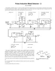
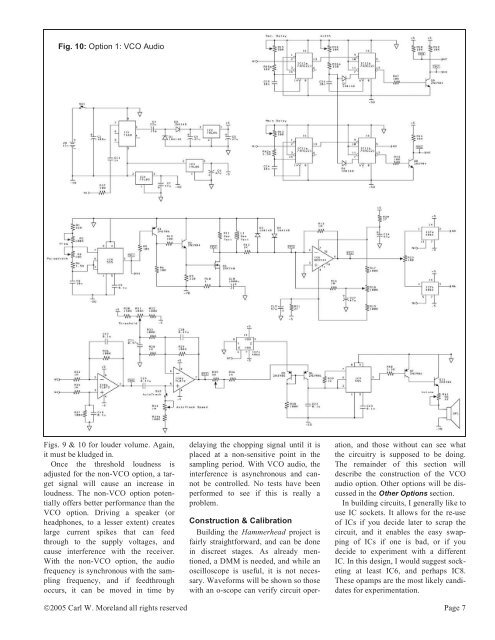
Fig. 10: Option 1: VCO Audio<br />
Figs. 9 & 10 for louder volume. Again,<br />
it must be kludged in.<br />
Once the threshold loudness is<br />
adjusted for the non-VCO option, a target<br />
signal will cause an increase in<br />
loudness. The non-VCO option potentially<br />
offers better performance than the<br />
VCO option. Driving a speaker (or<br />
headphones, to a lesser extent) creates<br />
large current spikes that can feed<br />
through to the supply voltages, and<br />
cause interference with the receiver.<br />
With the non-VCO option, the audio<br />
frequency is synchronous with the sampling<br />
frequency, and if feedthrough<br />
occurs, it can be moved in time by<br />
delaying the chopping signal until it is<br />
placed at a non-sensitive point in the<br />
sampling period. With VCO audio, the<br />
interference is asynchronous and cannot<br />
be controlled. No tests have been<br />
performed to see if this is really a<br />
problem.<br />
Construction & Calibration<br />
Building the <strong>Hammerhead</strong> project is<br />
fairly straightforward, and can be done<br />
in discreet stages. As already mentioned,<br />
a DMM is needed, and while an<br />
oscilloscope is useful, it is not necessary.<br />
Waveforms will be shown so those<br />
with an o-scope can verify circuit oper-<br />
ation, and those without can see what<br />
the circuitry is supposed to be doing.<br />
The remainder of this section will<br />
describe the construction of the VCO<br />
audio option. Other options will be discussed<br />
in the Other Options section.<br />
In building circuits, I generally like to<br />
use IC sockets. It allows for the re-use<br />
of ICs if you decide later to scrap the<br />
circuit, and it enables the easy swapping<br />
of ICs if one is bad, or if you<br />
decide to experiment with a different<br />
IC. In this design, I would suggest socketing<br />
at least IC6, and perhaps IC8.<br />
These opamps are the most likely candidates<br />
for experimentation.<br />
©2005 Carl W. Moreland all rights reserved Page 7