Assembly Instructions for H- and B Guide with Linear Motor - LinMot
Assembly Instructions for H- and B Guide with Linear Motor - LinMot
Assembly Instructions for H- and B Guide with Linear Motor - LinMot

You also want an ePaper? Increase the reach of your titles
YUMPU automatically turns print PDFs into web optimized ePapers that Google loves.
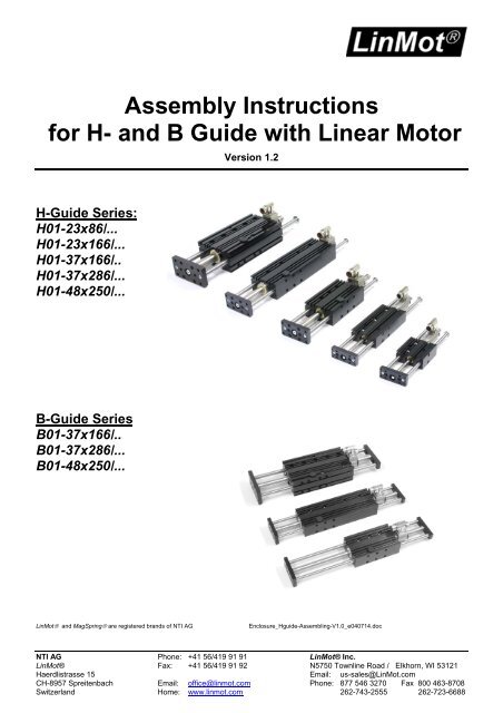
<strong>Assembly</strong> <strong>Instructions</strong><br />
<strong>for</strong> H- <strong>and</strong> B <strong>Guide</strong> <strong>with</strong> <strong>Linear</strong> <strong>Motor</strong><br />
Version 1.2<br />
H-<strong>Guide</strong> Series:<br />
H01-23x86/...<br />
H01-23x166/...<br />
H01-37x166/..<br />
H01-37x286/...<br />
H01-48x250/... B01-48x250/...<br />
B-<strong>Guide</strong> Series<br />
B01-37x166/..<br />
B01-37x286/...<br />
B01-48x250/...<br />
<strong>LinMot</strong>® <strong>and</strong> MagSpring® are registered br<strong>and</strong>s of NTI AG Enclosure_Hguide-Assembling-V1.0_e040714.doc<br />
NTI AG Phone: +41 56/419 91 91 <strong>LinMot</strong>® Inc.<br />
<strong>LinMot</strong>® Fax: +41 56/419 91 92 N5750 Townline Road / Elkhorn, WI 53121<br />
Haerdlistrasse 15 Email: us-sales@<strong>LinMot</strong>.com<br />
CH-8957 Spreitenbach Email: office@linmot.com Phone: 877 546 3270 Fax 800 463-8708<br />
Switzerl<strong>and</strong> Home: www.linmot.com 262-743-2555 262-723-6688
Assembling H-<strong>and</strong> B-<strong>Guide</strong><br />
H-<strong>Guide</strong>s<br />
.<br />
NTI AG / <strong>LinMot</strong> www.<strong>LinMot</strong>.com Enclosure_H-B_guide-Assembling-V1.2_e
Assembling H-<strong>and</strong> B-<strong>Guide</strong><br />
Part List H-<strong>Guide</strong>s<br />
NTI AG / <strong>LinMot</strong> www.<strong>LinMot</strong>.com Enclosure_H-B_guide-Assembling-V1.2_e
Assembling H-<strong>and</strong> B-<strong>Guide</strong><br />
B-<strong>Guide</strong>s<br />
NTI AG / <strong>LinMot</strong> www.<strong>LinMot</strong>.com Enclosure_H-B_guide-Assembling-V1.2_e
Assembling H-<strong>and</strong> B-<strong>Guide</strong><br />
Part List B-<strong>Guide</strong>s<br />
. .<br />
NTI AG / <strong>LinMot</strong> www.<strong>LinMot</strong>.com Enclosure_H-B_guide-Assembling-V1.2_e
Assembling H-<strong>and</strong> B-<strong>Guide</strong><br />
1a<br />
1c<br />
2a<br />
2c<br />
2e<br />
Mounting plate, rods , safety washers, screws<br />
Mounting plate detail<br />
1. Pre-assemble <strong>Guide</strong> Unit<br />
NTI AG / <strong>LinMot</strong> www.<strong>LinMot</strong>.com Enclosure_H-B_guide-Assembling-V1.2_e<br />
1b<br />
1d<br />
2. Mounting of Stator into the <strong>Guide</strong> Flange<br />
Stator, <strong>Guide</strong> Flange, clamping elements <strong>and</strong> screws<br />
Place clamping elements into <strong>Guide</strong> Flange (do not<br />
tighten screws)<br />
Tighten stator clamping screws ( torque: 200 Ncm<br />
(1.47 ft lbs)).<br />
2b<br />
2d<br />
Fasten mounting plate to the rods <strong>with</strong> screws<br />
provided (Loctite 243).<br />
Assembled <strong>Guide</strong> Unit (<strong>with</strong>out safety washers)<br />
Clamping element <strong>and</strong> M5x18 screw.<br />
Insert Stator (clamping parts may have to be<br />
moved)<br />
Assembled Unit. Check that end of stator is on<br />
the right side, mounting holes on the bottom.
Assembling H-<strong>and</strong> B-<strong>Guide</strong><br />
3a<br />
3c<br />
Slider <strong>and</strong> <strong>Guide</strong> Flange assembled <strong>with</strong> Stator<br />
Place lubricated (<strong>LinMot</strong> grease LU02) Slider<br />
into the Stator (End <strong>with</strong>out serial number)<br />
4a<br />
4c<br />
3. Placing Slider into Stator<br />
NTI AG / <strong>LinMot</strong> www.<strong>LinMot</strong>.com Enclosure_H-B_guide-Assembling-V1.2_e<br />
3b<br />
3d<br />
4. Insert <strong>Guide</strong> Unit into <strong>Guide</strong> Flange<br />
<strong>Guide</strong> Unit <strong>and</strong> <strong>Guide</strong> Flange<br />
Check that <strong>Guide</strong> Unit moves freely<br />
4b<br />
End of the slider <strong>with</strong> lasered serial number<br />
End of the slider <strong>with</strong> serial number must be on<br />
the <strong>for</strong>ward end as shown!<br />
Move lubricated (ball bearing grease eg.SKF<br />
LGMT2) <strong>Guide</strong> Unit slowly into <strong>Guide</strong><br />
If <strong>Guide</strong> Unit does not move freely in <strong>Guide</strong><br />
Flange, loosen mounting screws, move <strong>Guide</strong><br />
Unit completely into <strong>Guide</strong> Flange <strong>and</strong> tighten<br />
Mounting Plate screws again.
Assembling H-<strong>and</strong> B-<strong>Guide</strong><br />
5Ha<br />
5Hc<br />
5He<br />
5Hg<br />
5Hi<br />
5H. Installation of Slider <strong>and</strong> H- <strong>Guide</strong> Unit<br />
Mounting screw, adjustment washers (ball <strong>and</strong><br />
socket washers), dished washer<br />
Place ball washer size M6 ! or M8 on screw.<br />
(Its socket is milled into the mounting plate)<br />
<strong>and</strong> slide screw through hole in mounting plate.<br />
Detail: Ball <strong>and</strong> socket washer, disc spring<br />
Move <strong>Guide</strong> Unit out <strong>and</strong> re-tighten the screw<br />
using a wrench on slider (Loctite 243).<br />
Fasten safety washers to end of <strong>Guide</strong> rods.<br />
5Hb<br />
5Hd<br />
5Hf<br />
5Hh<br />
Function: Ball <strong>and</strong> socket washers adjust <strong>for</strong><br />
angular offset between linear motor slider <strong>and</strong><br />
<strong>Guide</strong> Unit<br />
Place second ball, socket washer (M5 or M8)<br />
<strong>and</strong> disc spring on screw <strong>and</strong> start screw into<br />
slide threads.<br />
Move <strong>Guide</strong> Unit completely into Flange <strong>and</strong><br />
then tighten screw.<br />
If slider <strong>and</strong> <strong>Guide</strong> Unit do not move freely,<br />
loosen screw <strong>and</strong> start again at step 5f .<br />
Assembled Unit<br />
NTI AG / <strong>LinMot</strong> www.<strong>LinMot</strong>.com Enclosure_H-B_guide-Assembling-V1.2_e
Assembling H-<strong>and</strong> B-<strong>Guide</strong><br />
5Ba<br />
5Bc<br />
5Be<br />
5B. Installation of Slider <strong>and</strong> B- <strong>Guide</strong> Unit<br />
.<br />
Insert Stator into <strong>Guide</strong><br />
Check: End of the slider <strong>with</strong> serial number<br />
must be on the <strong>for</strong>ward end as shown!<br />
!<br />
Mount ‘Rear end stop Ring’ <strong>and</strong> Rear plate<br />
(note side <strong>and</strong> direction of plate!)<br />
Fasten Front Srew<br />
5Bb<br />
5Bd<br />
5Bf<br />
Place front plate <strong>with</strong> rods<br />
Note side <strong>and</strong> direction of rear plate<br />
Assembled Unit<br />
NTI AG / <strong>LinMot</strong> www.<strong>LinMot</strong>.com Enclosure_H-B_guide-Assembling-V1.2_e
Assembling H-<strong>and</strong> B-<strong>Guide</strong><br />
6a<br />
6c<br />
7a<br />
7c<br />
Fan <strong>with</strong> guard (blow direction against flange),<br />
spacers, rectancular nuts<br />
Place fan on H-<strong>Guide</strong> <strong>with</strong> rectancular nuts in ’T’slot<br />
of H-<strong>Guide</strong>, tighten screws.<br />
6. Installing cooling fan<br />
NTI AG / <strong>LinMot</strong> www.<strong>LinMot</strong>.com Enclosure_H-B_guide-Assembling-V1.2_e<br />
6b<br />
6d<br />
Fan <strong>with</strong> pre-assembled mounting parts.<br />
Assembled Unit <strong>with</strong> fan. Blow direction against<br />
flange!<br />
7. Installing pneumatic brake (‘37’ <strong>and</strong> ‘48’models only)<br />
<strong>Guide</strong> Unit, <strong>Guide</strong> Flange <strong>with</strong> linear motor <strong>and</strong><br />
brake<br />
Insert brake <strong>and</strong> move <strong>Guide</strong> Unit slowly into the<br />
Flange, passing rod through bore of brake<br />
assembly.<br />
7b<br />
7d<br />
Function: The brake is spring loaded to clamp<br />
the rod when air pressure is released.<br />
Assembled H-<strong>Guide</strong> <strong>with</strong> brake
Assembling H-<strong>and</strong> B-<strong>Guide</strong><br />
8a<br />
8c<br />
8e<br />
8g<br />
8i<br />
8. Mounting of the magnetic spring MagSpring®<br />
Parts: ’H’-<strong>Guide</strong> <strong>Assembly</strong>, MagSpring, Mounting<br />
Flange, Coupling , Misc. Hardware<br />
Place Flange on ’H’-<strong>Guide</strong> <strong>with</strong> rectancular nuts in<br />
’T’-slot of H’-<strong>Guide</strong>.<br />
Insert MagSpring into mounting Flange <strong>and</strong> lightly<br />
tighten clamping screw<br />
Tighten mounting Flange screws (Note: <strong>with</strong> M01-37<br />
MagSprings it will be necessary to remove<br />
MagSpring from the mounting bracket in order to<br />
tighten mounting Flange screws – replace<br />
MagSpring)<br />
Attach coupling to end of MagSpring (M5x16, disc<br />
spring, Loctite 243) <strong>and</strong> clamp to H- <strong>Guide</strong> rod.<br />
NTI AG / <strong>LinMot</strong> www.<strong>LinMot</strong>.com Enclosure_H-B_guide-Assembling-V1.2_e<br />
8b<br />
8d<br />
8f<br />
8h<br />
8j<br />
Pre-assemble mounting screws <strong>and</strong> rectancular<br />
nuts on to mounting Flange.<br />
Tighten mounting Flange screws only enough to<br />
make mounting Flange ’snug’ on H-<strong>Guide</strong><br />
Align MagSpring <strong>with</strong> H-<strong>Guide</strong> rods. Note: Axis<br />
of MagSpring must be absolutely parallel to rods<br />
of H-<strong>Guide</strong><br />
Move Magspring to desired position <strong>and</strong> tighten<br />
clamping screw (200 Ncm (1.48 ft lbs).<br />
Check Alignment – all parts must move freely. If<br />
tight spots or resistance to free movement is<br />
noted, realign as necessary