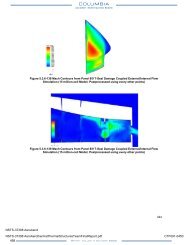
Facing the Heat Barrier - NASA's History Office
Facing the Heat Barrier - NASA's History Office
Facing the Heat Barrier - NASA's History Office

Create successful ePaper yourself
Turn your PDF publications into a flip-book with our unique Google optimized e-Paper software.
<strong>Facing</strong> <strong>the</strong> <strong>Heat</strong> <strong>Barrier</strong>: A <strong>History</strong> of Hypersonics<br />
nitrogen. This simulator was mounted on a universal joint, which allowed it to<br />
move freely in yaw, pitch, and roll.<br />
Reaction controls went into <strong>the</strong> X-1B late in 1957. The test pilot Neil Armstrong,<br />
who walked on <strong>the</strong> Moon 12 years later, made three flights in this research<br />
plane before it was grounded in mid-1958 due to cracks in its fuel tank. Its peak<br />
altitude during <strong>the</strong>se three flights was 55,000 feet, where its aerodynamic controls<br />
readily provided backup. The reaction controls <strong>the</strong>n went into an F-104, which<br />
reached 80,000 feet and went on to see much use in training X-15 pilots. When<br />
<strong>the</strong> X-15 was in flight, <strong>the</strong>se pilots had to transition from aerodynamic controls to<br />
reaction controls and back again. The complete system <strong>the</strong>refore provided overlap.<br />
It began blending in <strong>the</strong> reaction controls at approximately 85,000 feet, with most<br />
pilots switching to reaction controls exclusively by 100,000 feet. 67<br />
Since <strong>the</strong> war, with aircraft increasing in both speed and size, it had become<br />
increasingly impractical for a pilot to exert <strong>the</strong> physical strength to operate a plane’s<br />
ailerons and elevators merely by moving <strong>the</strong> control stick in <strong>the</strong> cockpit. Hydraulically-boosted<br />
controls thus were in <strong>the</strong> forefront, resembling power steering in a car.<br />
The X-15 used such hydraulics, which greatly eased <strong>the</strong> workload on a test pilot’s<br />
muscles. These hydraulic systems also opened <strong>the</strong> way for stability augmentation<br />
systems of increasing sophistication.<br />
Stability augmentation represented a new refinement of <strong>the</strong> autopilot. Conventional<br />
autopilots used gyroscopes to detect deviations from a plane’s straight and<br />
level course. These instruments <strong>the</strong>n moved an airplane’s controls so as to null <strong>the</strong>se<br />
deviations to zero. For high-performance jet fighters, <strong>the</strong> next step was stability<br />
augmentation. Such aircraft often were unstable in flight, tending to yaw or roll;<br />
indeed, designers sometimes enhanced this instability to make <strong>the</strong>m more maneuverable.<br />
Still, it was quite wearying for a pilot to have to cope with this. A stability<br />
augmentation system made life in <strong>the</strong> cockpit much easier.<br />
Such a system used rate gyros, which detected rates of movement in pitch, roll,<br />
and yaw at so many degrees per second. The instrument <strong>the</strong>n responded to <strong>the</strong>se<br />
rates, moving <strong>the</strong> controls somewhat like before to achieve a null. Each axis of this<br />
control had “gain,” defining <strong>the</strong> proportion or ratio between a sensed rate of angular<br />
motion and an appropriate deflection of ailerons or o<strong>the</strong>r controls. Fixed-gain<br />
systems worked well; <strong>the</strong>re also were variable-gain arrangements, with <strong>the</strong> pilot setting<br />
<strong>the</strong> value of gain within <strong>the</strong> cockpit. This addressed <strong>the</strong> fact that <strong>the</strong> airplane<br />
might need more gain in thin air at high altitude, to deflect <strong>the</strong>se surfaces more<br />
strongly. 68<br />
The X-15 program built three of <strong>the</strong>se aircraft. The first two used a stability augmentation<br />
system that incorporated variable gain, although in practice <strong>the</strong>se aircraft<br />
flew well with constant values of gain, set in flight. 69 The third replaced it with a<br />
more advanced arrangement that incorporated something new: adaptive gain. This<br />
76<br />
The X-15<br />
was a variable gain, which changed automatically in response to flight conditions.<br />
Within <strong>the</strong> Air Force, <strong>the</strong> Flight Control Laboratory at WADC had laid groundwork<br />
with a program dating to 1955. Adaptive-gain controls flew aboard F-94 and<br />
F-101 test aircraft. The X-15 system, <strong>the</strong> Minneapolis Honeywell MH-96, made its<br />
first flight in December 1961. 70<br />
How did it work? When a pilot moved <strong>the</strong> control stick, as when changing <strong>the</strong><br />
pitch, <strong>the</strong> existing value of gain in <strong>the</strong> pitch channel caused <strong>the</strong> aircraft to respond<br />
at a certain rate, measured by a rate gyro. The system held a stored value of <strong>the</strong><br />
optimum pitch rate, which reflected preferred handling qualities. The adaptive-gain<br />
control compared <strong>the</strong> measured and desired rates and used <strong>the</strong> difference to determine<br />
a new value for <strong>the</strong> gain. Responding rapidly, this system enabled <strong>the</strong> airplane<br />
to maintain nearly constant control characteristics over <strong>the</strong> entire flight envelope. 71<br />
The MH-96 made it possible to introduce <strong>the</strong> X-15’s blended aerodynamic and<br />
reaction controls on <strong>the</strong> same control stick. This blending occurred automatically<br />
in response to <strong>the</strong> changing gains. When <strong>the</strong> gains in all three channels—roll, pitch,<br />
and yaw—reached 80 percent of maximum, <strong>the</strong>reby indicating an imminent loss of<br />
effectiveness in <strong>the</strong> aerodynamic controls, <strong>the</strong> system switched to reaction controls.<br />
During re-entry, with <strong>the</strong> airplane entering <strong>the</strong> sensible atmosphere, <strong>the</strong> system<br />
returned to aerodynamic control when all <strong>the</strong> gains dropped to 60 percent. 72<br />
The X-15 flight-control system thus stood three steps removed from <strong>the</strong> conventional<br />
stick-and-cable installations of World War II. It used hydraulically-boosted<br />
controls; it incorporated automatic stability augmentation; and with <strong>the</strong> MH-96,<br />
it introduced adaptive gain. Fly-by-wire systems lay ahead and represented <strong>the</strong> next<br />
steps, with such systems being built both in analog and digital versions.<br />
Analog fly-by-wire systems exist within <strong>the</strong> F-16A and o<strong>the</strong>r aircraft. A digital<br />
system, as in <strong>the</strong> space shuttle, uses a computer that receives data both from <strong>the</strong><br />
pilot and from <strong>the</strong> outside world. The pilot provides input by moving a stick or<br />
sidearm controller. These movements do not directly actuate <strong>the</strong> ailerons or rudder,<br />
as in days of old. Instead, <strong>the</strong>y generate signals that tell a computer <strong>the</strong> nature of<br />
<strong>the</strong> desired maneuver. The computer <strong>the</strong>n calculates a gain by applying control<br />
laws, which take account of <strong>the</strong> plane’s speed and altitude, as measured by onboard<br />
instruments. The computer <strong>the</strong>n sends commands down a wire to hydraulic actuators<br />
co-mounted with <strong>the</strong> controls to move or deflect <strong>the</strong>se surfaces so as to comply<br />
with <strong>the</strong> pilot’s wishes. 73<br />
The MH-96 fell short of such arrangements in two respects. It was analog, not<br />
digital, and it was a control system, not a computer. Like o<strong>the</strong>r systems executing<br />
automatic control, <strong>the</strong> MH-96 could measure an observed quantity such as pitch<br />
rate, compare it to a desired value, and drive <strong>the</strong> difference to zero. But <strong>the</strong> MH-96<br />
was wholly incapable of implementing a control law, programmed as an algebraic<br />
expression that required values of airspeed and altitude. Hence, while <strong>the</strong> X-15 with<br />
77