

1.2m & 1.5m Rotary Head (Heavy Duty) - McConnel
1.2m & 1.5m Rotary Head (Heavy Duty) - McConnel
1.2m & 1.5m Rotary Head (Heavy Duty) - McConnel

Create successful ePaper yourself
Turn your PDF publications into a flip-book with our unique Google optimized e-Paper software.
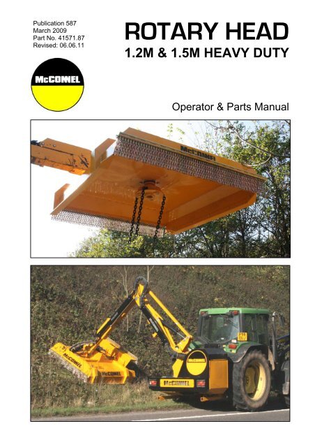
Publication 587<br />
March 2009<br />
Part No. 41571.87<br />
Revised: 06.06.11<br />
ROTARY HEAD<br />
1.2M & 1.5M HEAVY DUTY<br />
Operator & Parts Manual
IMPORTANT<br />
VERIFICATION OF WARRANTY REGISTRATION<br />
DEALER WARRANTY INFORMATION & REGISTRATION VERIFICATION<br />
It is imperative that the selling dealer registers this machine with <strong>McConnel</strong> Limited before<br />
delivery to the end user – failure to do so may affect the validity of the machine warranty.<br />
To register machines go to the <strong>McConnel</strong> Limited web site at www.mcconnel.com, log<br />
onto ‘Dealer Inside’ and select the ‘Machine Registration button’ which can be found in<br />
the Service Section of the site. Confirm to the customer that the machine has been<br />
registered in the section below.<br />
Should you experience any problems registering a machine in this manner please contact<br />
the <strong>McConnel</strong> Service Department on 01584 875848.<br />
Registration Verification<br />
Dealer Name: ……………………..…………………………………………………………….<br />
Dealer Address: …….………………………………………………………………………….<br />
Customer Name: ……………………..…………………………………………………………<br />
Date of Warranty Registration: ……/……/...…… Dealer Signature: ………………..……<br />
NOTE TO CUSTOMER / OWNER<br />
Please ensure that the above section above has been completed and signed by the selling<br />
dealer to verify that your machine has been registered with <strong>McConnel</strong> Limited.<br />
IMPORTANT: During the initial ‘bedding in’ period of a new machine it is the customer’s responsibility<br />
to regularly inspect all nuts, bolts and hose connections for tightness and re-tighten if required. New<br />
hydraulic connections occasionally weep small amounts of oil as the seals and joints settle in – where<br />
this occurs it can be cured by re-tightening the connection – refer to torque settings chart below. The<br />
tasks stated above should be performed on an hourly basis during the first day of work and at least<br />
daily thereafter as part of the machines general maintenance procedure.<br />
TORQUE SETTINGS FOR HYDRAULIC FITTINGS<br />
HYDRAULIC HOSE ENDS PORT ADAPTORS WITH BONDED SEALS<br />
BSP Setting Metric BSP Setting Metric<br />
1/4” 18 Nm 19 mm 1/4” 34 Nm 19 mm<br />
3/8” 31 Nm 22 mm 3/8” 47 Nm 22 mm<br />
1/2” 49 Nm 27 mm 1/2” 102 Nm 27 mm<br />
5/8” 60 Nm 30 mm 5/8” 122 Nm 30 mm<br />
3/4” 80 Nm 32 mm 3/4” 149 Nm 32 mm<br />
1” 125 Nm 41 mm 1” 203 Nm 41 mm<br />
1.1/4” 190 Nm 50 mm 1.1/4” 305 Nm 50 mm<br />
1.1/2” 250 Nm 55 mm 1.1/2” 305 Nm 55 mm<br />
2” 420 Nm 70 mm 2” 400 Nm 70 mm
WARRANTY POLICY<br />
WARRANTY REGISTRATION<br />
All machines must be registered, by the selling dealer with <strong>McConnel</strong> Ltd, before delivery to the end<br />
user. On receipt of the goods it is the buyer’s responsibility to check that the Verification of Warranty<br />
Registration in the Operator’s Manual has been completed by the selling dealer.<br />
1. LIMITED WARRANTIES<br />
1.01. All machines supplied by <strong>McConnel</strong> Limited are warranted to be free from defects in material<br />
and workmanship from the date of sale to the original purchaser for a period of 12 months,<br />
unless a different period is specified.<br />
1.02. All spare parts supplied by <strong>McConnel</strong> Limited are warranted to be free from defects in material<br />
and workmanship from the date of sale to the original purchaser for a period of 6 months.<br />
1.03. The manufacturer will replace or repair for the purchaser any part or parts found, upon<br />
examination at its factory, to be defective under normal use and service due to defects in<br />
material or workmanship. Returned parts must be complete and unexamined.<br />
1.04. This warranty does not apply to any part of the goods, which has been subjected to improper or<br />
abnormal use, negligence, alteration, modification, fitment of non-genuine parts, accident<br />
damage, or damage resulting from contact with overhead power lines, damage caused by<br />
foreign objects (e.g. stones, iron, material other than vegetation), failure due to lack of<br />
maintenance, use of incorrect oil or lubricants, contamination of the oil, or which has served its<br />
normal life. This warranty does not apply to any expendable items such as blades, flails, flap<br />
kits, skids, soil engaging parts, shields, guards, wear pads or pneumatic tyres.<br />
1.05. Temporary repairs and consequential loss - i.e. oil, downtime and associated parts are<br />
specifically excluded from the warranty.<br />
1.06. Warranty on hoses is limited to 12 months and does not include hoses which have suffered<br />
external damage. Only complete hoses may be returned under warranty, any which have been<br />
cut or repaired will be rejected.<br />
1.07. Machines must be repaired immediately a problem arises. Continued use of the machine after a<br />
problem has occurred can result in further component failures, for which <strong>McConnel</strong> Ltd cannot<br />
be held liable, and may have safety implications.<br />
1.08. Except as provided herein, no employee, agent, dealer or other person is authorised to give any<br />
warranties of any nature on behalf of <strong>McConnel</strong> Ltd.<br />
1.09. For machine warranty periods in excess of 12 months the following additional exclusions shall<br />
apply:<br />
1) Hoses, external seals, exposed pipes and hydraulic tank breathers.<br />
2) Filters.<br />
3) Rubber mountings.<br />
4) External electric wiring.<br />
1.10. All service work, particularly filter changes, must be carried out in accordance with the<br />
manufacturer’s service schedule. Failure to comply will invalidate the warranty. In the event of a<br />
claim, proof of the service work being carried out may be required.<br />
NB Warranty cover will be invalid if any non-genuine parts have been fitted or used. Use of<br />
non-genuine parts may seriously affect the machine’s performance and safety. <strong>McConnel</strong> Ltd<br />
cannot be held responsible for any failures or safety implications that arise due to the use of<br />
non-genuine parts.
2. REMEDIES AND PROCEDURES<br />
2.01. The warranty is not effective unless the Selling Dealer registers the machine, via the <strong>McConnel</strong><br />
web site and confirms the registration to the purchaser by completing the confirmation form in<br />
the operator’s manual.<br />
2.02. Any fault must be reported to an authorised <strong>McConnel</strong> dealer as soon as it occurs. Continued<br />
use of a machine, after a fault has occurred, can result in further component failure for which<br />
<strong>McConnel</strong> Ltd cannot be held liable.<br />
2.03. Repairs should be undertaken within two days of the failure. Claims submitted for repairs<br />
undertaken more than 2 weeks after a failure has occurred, or 2 days after the parts were<br />
supplied will be rejected, unless the delay has been authorised by <strong>McConnel</strong> Ltd.<br />
2.04. All claims must be submitted, by an authorised <strong>McConnel</strong> Service Dealer, within 30 days of the<br />
date of repair.<br />
2.05. Following examination of the claim and parts the manufacture will pay, at their discretion, for<br />
any valid claim the cost of any parts and an appropriate labour allowance if applicable.<br />
2.06. The submission of a claim is not a guarantee of payment.<br />
2.07. Any decision reached by <strong>McConnel</strong> Ltd. is final.<br />
3. LIMITATION OF LIABILITY<br />
3.01. The manufacturer disclaims any express (except as set forth herein) and implied warranties<br />
with respect to the goods including, but not limited to, merchantability and fitness for a particular<br />
purpose.<br />
3.02. The manufacturer makes no warranty as to the design, capability, capacity or suitability for use<br />
of the goods.<br />
3.03. Except as provided herein, the manufacturer shall have no liability or responsibility to the<br />
purchaser or any other person or entity with respect to any liability, loss, or damage caused or<br />
alleged to be caused directly or indirectly by the goods including, but not limited to, any indirect,<br />
special, consequential, or incidental damages resulting from the use or operation of the goods<br />
or any breach of this warranty. Notwithstanding the above limitations and warranties, the<br />
manufacturer’s liability hereunder for damages incurred by the purchaser or others shall not<br />
exceed the price of the goods.<br />
3.04. No action arising out of any claimed breach of this warranty or transactions under this warranty<br />
may be brought more than one (1) year after the cause of the action has occurred.<br />
4. MISCELLANEOUS<br />
4.01. The manufacturer may waive compliance with any of the terms of this limited warranty, but no<br />
waiver of any terms shall be deemed to be a waiver of any other term.<br />
4.02. If any provision of this limited warranty shall violate any applicable law and is held to be<br />
unenforceable, then the invalidity of such provision shall not invalidate any other provisions<br />
herein.<br />
4.03. Applicable law may provide rights and benefits to the purchaser in addition to those provided<br />
herein.
We,<br />
DECLARATION OF CONFORMITY<br />
Conforming to EU Machinery Directive 2006/42/EC<br />
McCONNEL LIMITED, Temeside Works, Ludlow, Shropshire SY8 1JL, UK<br />
Hereby declare that:<br />
The Product; Hydraulic Arm Mounted <strong>Rotary</strong> Cutting <strong>Head</strong><br />
Product Code; ROHD<br />
Serial No. & Date ………………………………… Type …………………………<br />
Manufactured in; United Kingdom<br />
Complies with the required provisions of the Machinery Directive 2006/42/EC<br />
The machinery directive is supported by the following harmonized standards;<br />
BS EN ISO 14121-1 (2007) Safety of machinery - Risk assessment, Part 1:<br />
Principles Part 2: practical guide and examples of methods.<br />
BS EN ISO 12100-1 (2010) Safety of machinery - Part 1: Basic terminology and<br />
methodology Part 2: Technical principles.<br />
BS EN 349(1993)+ A1 (2008) Safety of machinery - Minimum distances to avoid the<br />
entrapment with human body parts.<br />
BS EN 953 (1998) Safety of machinery - Guards General requirements for the<br />
design and construction of fixed and movable guards.<br />
BS EN 982(1996)+ A1 (2008) Safety requirements for fluid power systems and their<br />
components. Hydraulics<br />
McCONNEL LIMITED operates an ISO 9001:2008 quality management system,<br />
certificate number: FM25970.<br />
This system is continually assessed by the;<br />
British Standards Institution (BSI), Beech House, Milton Keynes, MK14 6ES, UK<br />
BSI is accredited by UK Accreditation Service, accreditation number: UKAS 003.<br />
The EC declaration only applies if the machine stated above is used in<br />
accordance with the operating instructions.<br />
Signed …………………................ Responsible Person<br />
on behalf of McCONNEL LIMITED<br />
Status: General Manager Date: May 2011
CONTENTS<br />
Page No.<br />
Operator Section<br />
General Information 2<br />
Specifications 3<br />
Component Location & Identification 3<br />
Safety Information 4<br />
Vehicle Preparation 8<br />
Operation 9<br />
Transportation 13<br />
Maintenance 13<br />
Parts Section<br />
<strong>Head</strong> Casing Assembly – <strong>1.2m</strong> Models 16<br />
<strong>Head</strong> Casing Assembly – <strong>1.5m</strong> Models 18<br />
Chain Guard Assembly – <strong>1.2m</strong> Models 20<br />
Chain Guard Assembly – <strong>1.5m</strong> Models 21<br />
Pivoting Mounting Bracket 22<br />
Bearing Unit 23<br />
Piston Motor – <strong>1.2m</strong> Models 24<br />
Gear Motor – <strong>1.2m</strong> Models 25<br />
Gear Motor – <strong>1.5m</strong> Models 26<br />
Cutting Chain Assembly (<strong>Heavy</strong> <strong>Duty</strong>) – <strong>1.2m</strong> Models 27<br />
Cutting Chain Assembly (Standard <strong>Duty</strong>) – <strong>1.5m</strong> Models 28<br />
Cutting Chain Assembly (<strong>Heavy</strong> <strong>Duty</strong>) – <strong>1.5m</strong> Models 29<br />
Blade Bar Assembly – <strong>1.5m</strong> Models 30<br />
Stop Module 31<br />
Hydraulic Installation – <strong>1.2m</strong> Gear Models 32<br />
Hydraulic Installation – <strong>1.2m</strong> Piston Models 34<br />
Hydraulic Installation – <strong>1.5m</strong> Piston Models 36<br />
Hydraulic Ram Assembly 38<br />
Decal Kit – <strong>1.2m</strong> Models 29<br />
Decal Kit – <strong>1.5m</strong> Models 30
GENERAL INFORMATION<br />
Read this manual before fitting or operating this equipment. Whenever any doubt<br />
exists contact your dealer or the <strong>McConnel</strong> Service Department for assistance.<br />
Always use ‘Genuine <strong>McConnel</strong> Parts’ on <strong>McConnel</strong> machinery and accessories.<br />
DEFINITIONS:<br />
The following definitions apply throughout this manual:<br />
WARNING:<br />
An operating procedure, technique etc., which can result in personal injury or loss of life if<br />
not observed carefully.<br />
CAUTION:<br />
An operating procedure, technique etc., which can result in the damage of either machine<br />
or equipment if not observed carefully.<br />
NOTE:<br />
An operating procedure, technique etc. which is considered essential to emphasise.<br />
LEFT & RIGHT HAND:<br />
This term is applicable to the machine when it is fitted to the tractor and viewed from the<br />
rear. This also applies to tractor references.<br />
Record the serial number of your machine on this page and always quote this number<br />
when ordering spares. Whenever information concerning the machine is requested<br />
remember to also state the type of tractor to which it is fitted.<br />
MACHINE SERIAL NUMBER:<br />
MODEL DETAILS:<br />
DEALER NAME & ADDRESS:<br />
DEALER TELEPHONE NUMBER:<br />
NOISE STATEMENT<br />
2<br />
INSTALLATION DATE:<br />
The equivalent daily personal noise exposure from this machine, measured at the operators’ ear,<br />
is within the range 78 – 85 DB. These figures apply to a normal distribution of use where the<br />
noise fluctuates between zero and maximum. The figures assume that the machine is fitted to a<br />
tractor with a quiet cab with the windows closed in a generally open environment. We<br />
recommend that the windows are kept closed. With the cab rear window open the equivalent daily<br />
personal noise exposure will increase to a figure within the range 82 – 88 DB. At equivalent daily<br />
noise exposure levels of between 85 and 90 DB, ear protection is recommended, it should be<br />
used if any window is left open.
SPECIFICATIONS<br />
Specifications RH1200 RH1500<br />
Working Width <strong>1.2m</strong> (48”) <strong>1.5m</strong> (60”)<br />
Choice of Cutting Units 3 x Ø13mm Chains 3 x Ø10mm Chains or D/Edge Blade Bar<br />
Length 1.7m (58”) 2.0m (78”)<br />
Width 1.6m (63”) 1.9m (75”)<br />
Height 0.62m – 0.67m (24.5” – 26”) 0.62m – 0.67m (24.5” – 26”)<br />
Deck Material Domex 700MC Domex 700MC<br />
Side Wall Thickness 6mm (0.23”) 6mm (0.23”)<br />
Safety Guarding <strong>Heavy</strong> <strong>Duty</strong> Overlapping Chain Guards <strong>Heavy</strong> <strong>Duty</strong> Overlapping Chain Guards<br />
Height Adjustment Adjustable Skids Adjustable Skids<br />
Cutting Height 100mm, 125mm or 150mm (4”, 5” or 6”) 100mm, 125mm or 150mm (4”, 5” or 6”)<br />
Front Hood Hydraulically Adjusted (110° action) Hydraulically Adjusted (110° action)<br />
Mounting Attachment 80x80x270 RHS 80x80x270 RHS<br />
Pivot Fully Floating +7° Fully Floating ±7°<br />
Hydraulic Flow 125 l/min 125 l/min<br />
Hydraulic Pressure (Max) 210Bar 210Bar<br />
Motor Type Gear or Piston Gear<br />
Options<br />
Cutting Unit - <strong>Heavy</strong> <strong>Duty</strong> Ø13mm Chain Cutting Unit<br />
Rubber Flaps - Light <strong>Duty</strong> Front & Rear Rubber Flaps<br />
COMPONENT LOCATION & IDENTIFICATION<br />
A) Deck<br />
B) Front Hood<br />
C) Hydraulic Hood Ram<br />
D) Chain Safety Guarding<br />
E) Side Skids<br />
F) Pivoting Mounting Bracket<br />
G) Hydraulic Motor<br />
H) Cutting Unit (Blade type shown)<br />
I ) Stop Assembly<br />
3<br />
<strong>1.5m</strong> <strong>Head</strong> with blade cutting unit illustrated
SAFETY SECTION<br />
SAFETY<br />
INFORMATION<br />
This component / accessory is primarily designed for fitment to <strong>McConnel</strong> Power Arm Hedge<br />
and Grass Cutters, therefore all safety aspects for this component relate to the safe use of<br />
those machines and will be stated in the safety section of its operation manual. A copy of the<br />
same safety information is provided below in order to reiterate and refresh your memory.<br />
This machine has the potential to be extremely dangerous, in the wrong hands it can kill or<br />
maim. It is therefore imperative that the owner, and the operator of this machine, read the<br />
following section to ensure that they are both fully aware of the dangers that do, or may<br />
exist, and their responsibilities surrounding its use.<br />
The operator of this machine is responsible not only for their own safety but equally for the<br />
safety of others who may come into the close proximity of the machine, as the owner you<br />
are responsible for both.<br />
POTENTIAL SIGNIFICANT DANGERS ASSOCIATED WITH THE USE OF A MACHINE:<br />
▲ Being hit by debris thrown by rotating components.<br />
▲ Being hit by machine parts ejected through damage during use.<br />
▲ Being caught on a rotating power take-off (PTO) shaft.<br />
▲ Being caught in other moving parts i.e.: belts, pulleys and cutting heads.<br />
▲ Electrocution from Overhead Power Lines (by contact with or ‘flashover’ from).<br />
▲ Being hit by cutting heads or machine arms as they move.<br />
▲ Becoming trapped between tractor and machine when hitching or unhitching.<br />
▲ Tractor overbalancing when machine arm is extended.<br />
▲ Injection of high-pressure oil from hydraulic hoses or couplings.<br />
▲ Machine overbalancing when freestanding (out of use).<br />
▲ Road traffic accidents due to collision or debris on the road.<br />
4
BEFORE USING A MACHINE YOU MUST:<br />
▲ Ensure you read all sections of the operator handbook.<br />
▲ Ensure the operator is, or has been, properly trained to use the machine.<br />
▲ Ensure the operator has been issued with and reads the operator handbook.<br />
▲ Ensure the operator understands and follows the instructions in operator handbook.<br />
▲ Ensure the tractor front, rear and sides are fitted with metal mesh or polycarbonate<br />
guards of suitable size and strength to protect the operator against thrown debris or<br />
parts.<br />
▲ Ensure tractor guards are fitted correctly, are undamaged and kept properly<br />
maintained.<br />
▲ Ensure that all machine guards are in position, are undamaged, and are kept<br />
maintained in accordance with the manufacturer’s recommendations.<br />
▲ Ensure that chains/blades and all fixings are genuine components supplied by the<br />
manufacturer specifically for the machine and are securely attached with no parts<br />
missing or damaged.<br />
▲ Ensure chain wear does not exceed the following limits;<br />
For 10mm chains all links must have a minimum thickness of 8mm.<br />
For 13mm chains all links must have a minimum thickness of 10mm.<br />
▲ Ensure all chains are the same length to maintain balance of the cutting unit.<br />
▲ Ensure hydraulic pipes are carefully and correctly routed to avoid damage by chaffing,<br />
stretching or pinching and that they are held in place with the correct fittings.<br />
▲ Always follow the manufacturer’s instructions for attachment and removal of the<br />
machine from the tractor.<br />
▲ Check that the machine fittings and couplings are in good condition.<br />
▲ Ensure the tractor meets the minimum weight recommendations of the machine’s<br />
manufacturer and that ballast is used as necessary.<br />
▲ Always inspect the work area thoroughly before starting to note obstacles and remove<br />
wire, bottles, cans and other debris.<br />
▲ Use clear suitably sized warning signs to alert others to the nature of the machine<br />
working within that area. Signs should be placed at both ends of the work site. (It is<br />
recommended that signs used are of a size and type specified by the Department of<br />
Transport and positioned in accordance with their, and the Local Highways Authority,<br />
guidelines).<br />
▲ Ensure the operator is protected from noise. Ear defenders should be worn and tractor<br />
cab doors and windows must be kept closed. Machine controls should be routed<br />
through proprietary openings in the cab to enable all windows to be shut fully.<br />
▲ Always work at a safe speed taking account of the conditions i.e.: terrain, highway<br />
proximity and obstacles around and above the machine. Extra special attention should<br />
be applied to Overhead Power Lines. Some of our machines are capable of reach in<br />
excess of 8 metres (26 feet) this means they have the potential to well exceed, by<br />
possibly 3 metres (9’ 9”), the lowest legal minimum height of 5.2 metres from the<br />
ground for 11,000 and 33,000 volt power lines. It cannot be stressed enough the<br />
dangers that surround this capability, it is therefore vital that the operator is fully aware<br />
of the maximum height and reach of the machine, and that they are fully conversant<br />
with all aspects regarding the safe minimum distances that apply when working with<br />
5
machines in close proximity to Power Lines. (Further information on this subject can be<br />
obtained from the Health & Safety Executive or your Local Power Company).<br />
▲ Always disengage the machine, kill the tractor engine, remove and pocket the key<br />
before dismounting for any reason.<br />
▲ Always clear up all debris left at the work area, it may cause hazard to others.<br />
▲ Always ensure when you remove your machine from the tractor that it is left in a safe<br />
and stable position using the stands and props provided and secured if necessary.<br />
WHEN NOT TO USE THIS MACHINE:<br />
▲ Never attempt to use this machine if you have not been trained to do so.<br />
▲ Never use a machine until you have read and understood the operator handbook, are<br />
familiar with it, and practiced the controls.<br />
▲ Never use a machine that is poorly maintained.<br />
▲ Never use a machine if guards are missing or damaged.<br />
▲ Never use a machine on which the hydraulic system shows signs of wear or damage.<br />
▲ Never fit, or use, a machine on a tractor that does not meet the manufacturer’s<br />
minimum specification level.<br />
▲ Never use a machine fitted to a tractor that does not have suitable front, rear and<br />
side(s) cab guarding made of metal mesh or polycarbonate.<br />
▲ Never use the machine if the tractor cab guarding is damaged, deteriorating or badly<br />
fitted.<br />
▲ Never turn a machine cutting head to an angle that causes debris to be ejected<br />
towards the cab.<br />
▲ Never start or continue to work a machine if people are nearby or approaching - Stop<br />
and wait until they are at a safe distance before continuing. WARNING: Some Cutting<br />
<strong>Head</strong>s may continue to ‘freewheel’ for up to 40 seconds after being stopped.<br />
▲ Never attempt to use a machine on materials in excess of its capability.<br />
▲ Never use a machine to perform a task it has not been designed to do.<br />
▲ Never operate the tractor or machine controls from any position other than from the<br />
driving seat, especially whilst hitching or unhitching the machine.<br />
▲ Never carry out maintenance of a machine or a tractor whilst the engine is running –<br />
the engine should be switched off, the key removed and pocketed.<br />
▲ Never leave a machine unattended in a raised position – it should be lowered to the<br />
ground in a safe position on a level firm site.<br />
▲ Never leave a tractor with the key in or the engine running.<br />
▲ Never carry out maintenance on any part or component of a machine that is raised<br />
unless that part or component has been properly substantially braced or supported.<br />
▲ Never attempt to detect a hydraulic leak with your hand – use a piece of cardboard.<br />
▲ Never allow children near to, or play on, a tractor or machine under any circumstances.<br />
6
ADDITIONAL SAFETY ADVICE<br />
Training<br />
Operators need to be competent and fully capable of operating this machine in a safe and<br />
efficient way prior to attempting to use it in any public place. We advise therefore that the<br />
prospective operator make use of relevant training courses available such as those run by<br />
the Agricultural Training Board, Agricultural Colleges, Dealers and <strong>McConnel</strong>.<br />
Working in Public Places<br />
When working in public places such as roadsides, consideration should be paid to others<br />
in the vicinity. Stop the machine immediately when pedestrians, cyclists and horse riders<br />
etc. pass. Restart only when they are at a distance that causes no risk to their safety.<br />
Warning Signs<br />
It is advisable that any working area be covered by suitable warning signs and statutory in<br />
public places. Signs should be highly visible and well placed in order to give clear<br />
advanced warning of the hazard. Contact the Department of Transport or your Local<br />
Highways Authority to obtain detailed information on this subject. The latter should be<br />
contacted prior to working on the public highway advising them of the time and location of<br />
the intended work asking what is required by way of signs and procedure. – ‘Nonauthorised<br />
placement of road signs may create offences under the Highways Act’.<br />
Suggested Warning Signs Required<br />
“Road works ahead” warning sign with a supplementary “Hedge cutting” plate. “For 1<br />
mile” or appropriate shorter distance may be added to the plate.<br />
“Road narrows” warning sign with supplementary “Single file traffic” plate.<br />
White on blue “Keep right” (*) arrow sign on rear of machine.<br />
* Note – this applies to UK Market machines where traffic passes to the right of a machine<br />
working in the same direction as the traffic flow. The direction, use and colour of the arrow<br />
sign will depend on the country of use and the Local Highway Authorities regulations in the<br />
locality.<br />
Use of Warning Signs<br />
▲ On two-way roads one set of signs is needed facing traffic in each direction.<br />
▲ Work should be within 1 mile of the signs.<br />
▲ Work only when visibility is good and at times of low risk e.g.: NOT during ‘rush-hour’.<br />
▲ Vehicles should have an amber-flashing beacon.<br />
▲ Ideally, vehicles should be conspicuously coloured.<br />
▲ Debris should be removed from the road and path as soon as practicable, and at<br />
regular intervals, wearing high visibility clothing and before removing the hazard<br />
warning signs.<br />
▲ Collect all road signs promptly when the job is completed.<br />
Although the information given here covers a wide range of safety subjects, it is impossible to<br />
predict every eventuality that can occur under differing circumstances whilst operating this<br />
machine. No advice given here can replace ‘good common sense’ and ‘total awareness’ at all times,<br />
but will go a long way towards the safe use of your <strong>McConnel</strong> machine.<br />
7
VEHICLE / TRACTOR PREPARATION<br />
We recommend vehicles are fitted with cabs<br />
using ‘safety glass’ windows and protective<br />
guarding when used with our machines.<br />
Fit Operator Guard (Part No. 7313324)<br />
using the hooks provided. Shape the mesh to<br />
cover all vulnerable areas. The driver must<br />
be looking through mesh and/or<br />
polycarbonate glazing when viewing the flail<br />
head in any working position - unless the<br />
vehicle/ cab manufacturer can demonstrate that the penetration resistance is equivalent to,<br />
or higher than, that provided by mesh/polycarbonate glazing. If the tractor has a roll bar<br />
only, a frame must be made to carry both mesh and polycarbonate glazing. The operator<br />
should also use personal protective equipment to reduce the risk of serious injury such as;<br />
eye protection (mesh visor to EN1731 or safety glasses to EN166), hearing protection to<br />
EN352, safety helmet to EN297, gloves, filter mask and high visibility clothing.<br />
Vehicle Ballast: It is imperative when attaching ‘third-party’ equipment to a vehicle that<br />
the maximum possible stability of the machine and vehicle combination is achieved – this<br />
can be accomplished by the utilisation of ‘ballast’ in order to counter-balance the additional<br />
equipment added.<br />
Front weights may be required for rear mounted machines to place 15% of total outfit<br />
weight on the front axle for stable transport on the road and to reduce ‘crabbing’ due to the<br />
drag of the cutting unit when working on the ground.<br />
Rear weights may be required to maintain a reasonable amount of rear axle load on the<br />
opposite wheel from the arms when in work; for normal off-ground work i.e. hedge cutting<br />
this should be 20% of rear axle weight or more for adequate control, and for ground work<br />
i.e. verge mowing with experienced operators, this can be reduced to 10%.<br />
All factors must be addressed in order to match the type and nature of the equipment<br />
added to the circumstances under which it will be used – in the instance of Power Arm<br />
Hedgecutters it must be remembered that the machines centre of gravity during work will<br />
be constantly moving and will differ from that during transport mode, therefore balance<br />
becomes critical.<br />
Factors that effect stability:<br />
■ Centre of gravity of the tractor/machine combination.<br />
■ Geometric conditions, e.g. position of the cutting head and ballast.<br />
■ Weight, track width and wheelbase of the tractor.<br />
■ Acceleration, braking, turning and the relative position of the cutting head during these operations.<br />
■ Ground conditions, e.g. slope, grip, load capability of the soil/surface.<br />
■ Rigidity of implement mounting.<br />
Suggestions to increase stability:<br />
■ Increasing rear wheel track; a vehicle with a wider wheel track is more stable.<br />
■ Ballasting the wheel; it is preferable to use external weights but liquid can be added to around 75% of the<br />
tyre volume – water with anti-freeze or the heavier Calcium Chloride alternative can be used.<br />
■ Addition of weights – care should be taken in selecting the location of the weights to ensure they are<br />
added to a position that offers the greatest advantage.<br />
■ Front axle locking (check with tractor manufacturer).<br />
NOTE: The advice above is offered as a guide for stability only and is not a guide to vehicle strength.<br />
It is recommended that you consult your vehicle manufacturer or local dealer to obtain specific<br />
advice on this subject, additionally advice should be sought from a tyre specialist with regard to tyre<br />
pressures and ratings suitable for the type and nature of the machine you intend to fit.<br />
8
OPERATION<br />
The <strong>Rotary</strong> <strong>Head</strong> was designed for cutting scrub, brush and foliage of up to 100mm (4”) in<br />
diameter or multiple branches that have a total cross section area of equivalent size. The<br />
machines feature a hydraulically operated front hood (adjustable to 110°) which can be<br />
opened to accept larger material into the cutting unit.<br />
Machines are available in a choice of either <strong>1.2m</strong> or <strong>1.5m</strong> working widths; <strong>1.2m</strong> machines<br />
are fitted with a Ø13mm chain unit whilst <strong>1.5m</strong> machines are fitted as standard with a<br />
Ø10mm chain unit with the option of either the heavier duty Ø13mm chain unit or double<br />
edged blade bar.<br />
Ø10mm chain unit - recommended for Grass Work<br />
Ø13mm chain unit - recommended for Scrub Work<br />
Cutting Direction<br />
It is recommended that the direction of cutting should always be such that the blades or<br />
chains are cutting away from the operator at the point where the material first enters the<br />
machine; i.e. anti-clockwise for left hand mounted machines and clockwise for right hand<br />
mounted machines (when viewed from above).<br />
WARNING! When rotating parts are in motion, serious injury may occur if caution is not<br />
adopted or danger is not recognized. Never allow bystanders within 300 feet of the<br />
machine when in operation Extreme care should be taken when operating near loose<br />
objects such as gravel, rocks and debris - these conditions should always be avoided.<br />
The rotating parts in this machine have been designed and tested for rugged use.<br />
However, they could fail upon impact with heavy solid objects - such as steel guard rails,<br />
concrete abutments, etc., causing them to be thrown at a very high velocity. Never allow<br />
the cutter head to contact such objects; inspecting the cutting area for such objects and<br />
removing them prior to mowing will help eliminate these potential hazards.<br />
9
Once on location, lower the mower deck slightly above the material to be cut, so the<br />
mower does not have to start under a load. With the tractor at an idle, engage mower.<br />
Bring tractor RPM up to the correct working speed (*) and slowly lower deck to ground<br />
level. Maintaining even speed will ensure a clean cut.<br />
(*) NOTE: Working speed will be dependant on the particular machine and model that this<br />
accessory is being operated on; refer to the operation manual for that machine for details.<br />
When mowing on the ground, the unit should always be ‘carried’ rather than ‘dragged’ on<br />
the skid skids. Dragging the unit will increase the side loads on the boom, decrease the<br />
horsepower available to the cutter head, and reduce the ability of the accumulator the<br />
carry part of the weight of the boom during mowing operations. It is recommended that it is<br />
carried in such a way that a proportion of its weight is supported by the boom of the<br />
operating machine, and a proportion carried by the side skids. When worked in this<br />
manner the skids, in association with the pivoted mounting, will allow it the freedom to<br />
follow the natural contours of the ground.<br />
During mowing operation the correct operating speed should be maintained to prevent<br />
radical changes in mower spindle speeds, reducing risk of cutter assembly damage.<br />
For cutting brush it is usually best to stop the tractor and swivel the boom and mower into<br />
foliage. The horizontal positioning action of the boom is designed to position the cutting<br />
head and provide a limited pressure relief when excessive pressure is applied to the<br />
boom. Never force the cutting head into heavy branches or stumps - damage to the unit<br />
may result.<br />
CAUTION! When using the rotary cutting head for trimming trees and shrubs, let the<br />
mower ‘saw' into them. Do not lower the mower head down directly onto a tree or<br />
stump. The mower blades are designed to cut with the end, any misuse can cause<br />
damage to the blade and risks placing the operator in a hazardous situation.<br />
CAUTION! Powering the boom down, forcing mower deck onto ground may damage<br />
mower deck and it's attachment to the boom, creating a potentially hazardous situation.<br />
CAUTION! DO NOT use excessive force when positioning cutting head into heavy<br />
branches or stumps. Damage to the unit may result. It is best to let the cutter head ‘eat<br />
away’ slowly at heavy cutting jobs.<br />
CAUTION! If foliage falls on top of mower deck causing tractor to become unstable,<br />
move the boom ‘Forward’ and ‘Out’ to relieve tipping of the tractor. Lower mower deck<br />
to ground and shut down unit. After all motion stops, remove foliage from mower deck.<br />
Machines fitted with Blade Units<br />
The mower will operate more efficiently in tougher conditions and with less power if the<br />
knives are kept sharp. If the mower begins to vibrate, stop the tractor, check for wire<br />
wrapped in the spindle or damaged knives. When replacing knives, replace all knives with<br />
new knives to ensure proper balance so the mower will not vibrate. Severe vibration will<br />
result, if knives with unequal wear are used.<br />
Begin a pass at the top side of the trees and work down with each consecutive pass.<br />
When cutting trees and shrubs, use a lower speed to allow the knives time to cut as well<br />
as mulch the foliage.<br />
10
WARNING! If bystanders approach within 300 feet while mower is in operation turn<br />
mower switch ‘OFF’ immediately. After shutdown, never leave the tractor or allow<br />
bystanders to approach within 300 FEET of the unit until all motion stops completely.<br />
If cutter shaft jams and stops, turn mower switch to ‘OFF’, and swivel boom ‘AFT’.<br />
Normally this action will clear the cutter head. If not, roll mower deck until adjacent to the<br />
secondary boom, and then lower boom to rest mower deck on ground. Shut off the tractor,<br />
set parking break, allow all motion to cease. At that point it is safe to leave the tractor and<br />
clear the cutter heads manually.<br />
If wires, rope or chains should become entangled in the rotor stop immediately to prevent<br />
damage or dangerous situations; stop the rotor and tractor and remove the starting key.<br />
Put working gloves on and clear the rotor with the aid of pliers or shears. Do not attempt to<br />
disentangle by inverting the rotational direction of the rotor.<br />
Begin each pass at the top side of the trees and work down with each consecutive pass.<br />
Use a low speed to allow the cutting blades time to mulch as well as cut the foliage. When<br />
the initial pass has been made, disengage the mower, and return boom to a safe travel<br />
position. Return to starting point and make next pass, etc..<br />
Hydraulic Front Hood<br />
The machine is fitted as standard with a hydraulically operated front hood; the hood can be<br />
opened (up to 110°) to allow access to denser materials. For safety reasons the machine<br />
should be operated with the hood set at the lowest position that still allows the material to<br />
be cut to freely enter the head.<br />
Pivoted Mounting<br />
The mounting bracket is pivoted to permit the<br />
unit deviation from the horizontal by ±7° on<br />
<strong>1.5m</strong> machines and +7° on <strong>1.2m</strong> machines;<br />
this is to allow the machine to follow the<br />
contours of the terrain on ground cutting work,<br />
thus providing a cleaner finish.<br />
Blade Nut Access Point<br />
A removable cover is located<br />
on the deck of the machine to<br />
allow access to the blade bolt<br />
nut. If removed for service or<br />
maintenance work always<br />
ensure it is correctly replaced<br />
before using the machine.<br />
11<br />
<strong>1.5m</strong> model illustrated
Deck Stop<br />
A Stop assembly is provided for placement on the connecting boom of the operating<br />
machine; it is multi-adjustable for use on 100mm square section or 100/110mm tapered<br />
section booms.<br />
Its function is primarily to stop the deck coming into contact with the machines arm<br />
components when the head is fully angled, but also acts as a support for the unit during<br />
transportation.<br />
The stop should be assembled to the required configuration to fit the specific boom and<br />
positioned on the boom at a height where the rubber buffers contact an outer point on the<br />
top of the deck when the unit is fully angled in either direction.<br />
12
TRANSPORTATION<br />
Transport Position<br />
When transporting between job sites, or between cutting passes, the following procedure<br />
should be followed; shut off the power to the cutting head and allow all motion to come to<br />
a complete stop. Raise the boom to its highest position taking care to avoid all overhead<br />
obstructions such as power cables, trees etc. Rotate the deck to a position where it<br />
contacts the stop buffer before then folding the arms of the machine into a position where<br />
it is as compact as possible. Fit and secure any transport locks and close the lift ram tap if<br />
applicable.<br />
Check before transporting that the unit has ample clearance from the tractor tyres and<br />
other tractor or machine components. The unit is now in position for transportation.<br />
Transport Speed<br />
Transport speeds should be kept to a minimum on uneven terrain, and in all conditions<br />
avoid driving at a speed which causes exaggerated bouncing as this will put unnecessary<br />
strain on the tractors top hitch position<br />
MAINTENANCE<br />
Maintenance duties on the machine have been kept to a minimum, the grease points<br />
indicated below should be lubricated on a daily basis prior to work and the level of oil in the<br />
bearing housing checked. Top up to plug level (if required) using EP90 gearbox oil.<br />
After work and always prior to storage the machine should be cleaned to remove dirt and<br />
debris. Grease points indicated above prior to storage.<br />
13
For best performance …<br />
USE ONLY GENUINE McCONNEL SERVICE PARTS<br />
To be assured of the latest design improvements purchase your<br />
‘Genuine Replacements’ from the ‘Original Equipment Manufacturer’<br />
McCONNEL LIMITED<br />
Through your local Dealer or Stockist<br />
Always quote:<br />
Machine Type<br />
Serial Number<br />
Part Number<br />
Design improvements may alter some of the parts listed in this manual –<br />
the latest part will always be supplied when it is interchangeable with an earlier one.<br />
15
1.2M ROTARY HEAD CASING ASSEMBLY<br />
Module(s): 1039733<br />
16<br />
McCONNEL
1.2M ROTARY HEAD CASING ASSEMBLY<br />
Module(s): 1039733<br />
REF. QTY. PART No. DESCRIPTION<br />
1039733 1.2M ROTARY HEAD CASING<br />
1 1 22286.05 FRONT HOOD<br />
2 1 22408.07 LH SKID<br />
3 1 22408.08 RH SKID<br />
4 1 22415.04 ROTARY HEAD CASING<br />
5 1 22421.01 PIVOT PIN<br />
6 1 41691.06 PIN<br />
7 1 41693.01 PIN<br />
8 20 9100105 FLAT WASHER<br />
9 8 9100106 FLAT WASHER<br />
10 12 9163005 NYLOC NUT<br />
11 5 9163006 NYLOC NUT<br />
12 2 9213266 BOLT<br />
13 10 9313065 SETSCREW<br />
14 2 9313075 SETSCREW<br />
15 1 9313076 SETSCREW<br />
16 2 9313106 SETSCREW<br />
17<br />
McCONNEL
1.5M ROTARY HEAD CASING ASSEMBLY<br />
Module(s): 1039730<br />
18<br />
McCONNEL
1.5M ROTARY HEAD CASING ASSEMBLY<br />
Module(s): 1039730<br />
REF. QTY. PART No. DESCRIPTION<br />
1039730 1.5M ROTARY HEAD CASING<br />
1 1 21833.01 COVER<br />
2 1 22286.04 FRONT HOOD<br />
3 1 22408.05 LH SKID<br />
1 22408.06 RH SKID<br />
4 1 22415.03 ROTARY HEAD CASING<br />
5 1 22421.01 PIVOT PIN<br />
6 1 41691.06 PIN<br />
7 1 41693.01 PIN<br />
8 2 9100104 FLAT WASHER<br />
9 20 9100105 FLAT WASHER<br />
10 8 9100106 FLAT WASHER<br />
11 2 9163004 NYLOC NUT<br />
12 12 9163005 NYLOC NUT<br />
13 5 9163006 NYLOC NUT<br />
14 10 9313065 SETSCREW<br />
15 2 9213266 BOLT<br />
16 2 9313075 SETSCREW<br />
17 1 9313076 SETSCREW<br />
18 2 9313106 SETSCREW<br />
19<br />
McCONNEL
CHAIN GUARD ASSEMBLIES – 1.2M Models<br />
Module(s): 1039734<br />
REF. QTY. PART No. DESCRIPTION<br />
1039734 CHAIN GUARD ASSEMBLIES<br />
1 2 22148.15 CHAIN RETAINING BAR<br />
2 1 22321.06 REAR CHAIN GUARD MOUNTING<br />
3 1 22321.07 FRONT CHAIN GUARD MOUNTING<br />
4 112 46943.21 CHAIN ASSEMBLY (7 LINKS)<br />
5 16 9100105 FLAT WASHER<br />
6 9 9163005 NYLOC NUT<br />
7 22 9300154 SOCKET SCREW<br />
20<br />
McCONNEL
CHAIN GUARD ASSEMBLIES – 1.5M Models<br />
Module(s): 1039718<br />
REF. QTY. PART No. DESCRIPTION<br />
1039718 CHAIN GUARD ASSEMBLIES<br />
1 2 22148.10 CHAIN RETAINING BAR<br />
2 1 22321.01 REAR CHAIN GUARD MOUNTING<br />
3 1 22321.03 FRONT CHAIN GUARD MOUNTING<br />
4 136 46943.21 CHAIN ASSEMBLY (7 LINKS)<br />
5 8 9100104 FLAT WASHER<br />
6 5 9100105 FLAT WASHER<br />
7 8 9163004 NYLOC NUT<br />
8 5 9163005 NYLOC NUT<br />
9 8 9313044 SETSCREW<br />
10 12 9313055 SETSCREW<br />
21<br />
McCONNEL
PIVOTING MOUNTING BRACKET ASSEMBLY<br />
Module(s): 1039715<br />
REF. QTY. PART No. DESCRIPTION<br />
1039715 PIVOTING MOUNTING BRACKET<br />
1 1 0901121 GREASE NIPPLE<br />
2 4 1337114 RUBBER BUFFER<br />
3 2 21385.01 BUSH<br />
4 1 22386.07 PIVOTING MOUNTING<br />
5 2 41580.01 PLASTIC PLUG<br />
6 1 7198330 CLAMP<br />
7 2 7198332 CLAMP<br />
8 2 8629219 ROTARY SHAFT SEAL<br />
9 4 9100105 FLAT WASHER<br />
10 8 9100024 SELF-LOCKING FLANGE NUT<br />
11 4 9163005 NYLOC NUT<br />
12 4 9200024 BOLT<br />
13 4 9210167 BOLT<br />
22<br />
McCONNEL
BEARING UNIT<br />
Module(s): 1039729<br />
REF. QTY. PART No. DESCRIPTION<br />
1039729 BEARING UNIT<br />
1 1 02960553B SPINDLE & HOUSING ASSEMBLY<br />
2 4 9100020 FLAT WASHER<br />
3 4 9100022 SELF-LOCKING NUT<br />
4 6 9163008 NYLOC NUT<br />
5 4 9200056 BOLT<br />
6 6 9213128 BOLT<br />
23<br />
McCONNEL
PISTON MOTOR – 1.2M Models<br />
Module(s): 1039741<br />
REF. QTY. PART No. DESCRIPTION<br />
1039741 PISTON MOTOR MODULE<br />
1 2 8002086 ADAPTOR<br />
2 1 8301326 PISTON MOTOR (60cc)<br />
3 1 8581211 EXTENSION ADAPTOR<br />
4 2 8581264 ADAPTOR - SWEPT 90°<br />
5 1 8581379 ADAPTER<br />
6 2 8581597 FLANGE<br />
7 1 8600910 O RING<br />
8 2 8650106 BONDED SEAL<br />
9 1 8650108 BONDED SEAL<br />
24<br />
McCONNEL
GEAR MOTOR (125L/min) – 1.2M Models<br />
Module(s): 1039746<br />
REF. QTY. PART No. DESCRIPTION<br />
1039746 MOTOR MODULE (125LPM)<br />
1 2 05.434.01 ADAPTOR<br />
2 1 46043.01 RIGID PIPE<br />
3 1 8301328 MOTOR (70cc)<br />
4 1 8581146 ADAPTOR EXTENSION<br />
5 2 8581566 FLANGE<br />
6 2 8650108 BONDED SEAL<br />
7 1 8650102 BONDED SEAL<br />
25<br />
McCONNEL
GEAR MOTOR (125L/min) – 1.5M Models<br />
Module(s): 1039724<br />
REF. QTY. PART No. DESCRIPTION<br />
1039724 GEAR MOTOR (125L/min)<br />
1 2 05.434.01 ADAPTOR (BSP)<br />
2 1 43506.01 HYDRAULIC MOTOR<br />
3 1 46043.01 RIGID PIPE<br />
4 1 8581115 ADAPTOR<br />
5 1 8650102 BONDED SEAL<br />
6 2 8650108 BONDED SEAL<br />
7 1 8600904 O RING<br />
8 1 8581458 ADAPTOR (UNF)<br />
26<br />
McCONNEL
1.2M CUTTING CHAIN ASSEMBLY (HEAVY DUTY)<br />
Module(s): 1039737<br />
REF. QTY. PART No. DESCRIPTION<br />
1039737 1.2M CUTTING CHAIN ASSEMBLY<br />
1 4 0312167 HEX SCREW<br />
2 3 12.714.75 BOLT<br />
3 1 22315.03 CHAINS Ø13mm (SET OF 3)<br />
4 1 22323.05 CHAIN MOUNTING HUB<br />
5 1 22327.02 CHAIN CLAMP PLATE<br />
6 1 22630.01 SPECIAL TAB WASHER<br />
7 3 T7942 NYLOC NUT<br />
27<br />
McCONNEL
1.5M CUTTING CHAIN ASSEMBLY (STD. DUTY)<br />
Module(s): 1039728<br />
REF. QTY. PART No. DESCRIPTION<br />
1039728 1.5M CUTTING CHAIN ASSEMBLY<br />
1 4 0312167 HEX SCREW<br />
2 3 12.714.75 BOLT<br />
3 1 22315.01 CHAINS Ø10mm (SET OF 3)<br />
4 1 22323.04 CHAIN MOUNTING HUB<br />
5 1 22327.02 CHAIN CLAMP PLATE<br />
6 1 22630.01 SPECIAL TAB WASHER<br />
7 3 T7942 NYLOC NUT<br />
28<br />
McCONNEL
1.5M CUTTING CHAIN ASSEMBLY (HEAVY DUTY)<br />
Module(s): 1039708<br />
REF. QTY. PART No. DESCRIPTION<br />
1039708 1.5M CHAIN CUTTING ASSEMBLY<br />
1 3 9210167 BOLT<br />
2 1 22315.02 CHAINS Ø13mm (SET OF 3)<br />
3 1 22323.03 CHAIN MOUNTING HUB<br />
4 1 22327.01 CHAIN CLAMP<br />
5 3 T7942 NYLOC NUT<br />
29<br />
McCONNEL
BLADE BAR ASSEMBLY<br />
Module(s): 02782300<br />
REF. QTY. PART No. DESCRIPTION<br />
02782300 BLADE BAR ASSEMBLY<br />
1 1 02781600 BLADE BAR LEAF (TOP)<br />
2 1 02781700 BLADE BAR LEAF (CENTRE)<br />
3 1 02781800 BLADE BAR LEAF (BOTTOM)<br />
4 1 02761500 BLADE SET<br />
5 2 02782900 BLADE BOLT<br />
6 4 00003901 SPRING WASHER<br />
7 4 02032200 SPRING WASHER<br />
8 4 02708700 SOCKET CAPSCREW<br />
9 2 02782100 HEX SCREW<br />
10 2 02782200 HEX SCREW<br />
11 2 02957089 SPRING WASHER<br />
12 2 00020900 FLANGE NUT (SLOTTED)<br />
13 2 00023200 ROLL PIN<br />
30<br />
McCONNEL
STOP MODULE<br />
Module(s): 1039720<br />
REF. QTY. PART No. DESCRIPTION<br />
1039720 STOP MODULE<br />
1 1 22425.01 STOP PRESSING - TOP<br />
2 1 22425.02 STOP PRESSING - BOTTOM<br />
3 2 22426.01 STOP MOUNTING PRESSING<br />
4 4 9100105 FLAT WASHER<br />
5 14 9163005 NYLOC NUT<br />
6 4 9213085 BOLT<br />
7 10 9313055 SETSCREW<br />
8 2 T7879 RUBBER BUFFER<br />
31<br />
McCONNEL
HYDRAULIC INSTALLATION – 1.2M Gear Model<br />
Module(s): 1039745<br />
32<br />
McCONNEL
HYDRAULIC INSTALLATION – 1.2M Gear Model<br />
Module(s): 1039745<br />
REF. QTY. PART No. DESCRIPTION<br />
1039745 HYDRAULIC INSTALLATION (GEAR)<br />
1 1 05.433.01 BLANKING PLUG C/W CONE<br />
2 2 05.433.03 MALE PLUG WITH CONE<br />
3 4 10.001.20 HOSE - 1/4" BSP FS/FS x 1000mm<br />
4 2 10.001.73 HOSE - 1/4" BSP FS/FS x 6300mm<br />
5 1 10.002.37 HOSE - 1/4" BSP FS/F90 x 2700mm<br />
6 1 10.002.40 HOSE - 1/4" BSP FS/F90 x 3000mm<br />
7 1 10.004.18 HOSE - 3/8" BSP FS/F90 x 900mm<br />
8 1 10.025.15 HOSE - 1" BSP FS/F135 x 750mm<br />
9 1 10.025.22 HOSE - 1" BSP FS/F135 x 1200mm<br />
10 1 22590.16 HOSE SLEEVING - 800mm<br />
11 1 22591.03 HOSE SLEEVING - 150mm<br />
12 2 520378 ADAPTOR PLUG<br />
13 4 7196045 HOSE TIE<br />
14 1 7560356 COMPENSATOR RAM<br />
15 6 8581169 ADAPTOR<br />
16 1 8581241 EXTENSION ADAPTOR<br />
17 1 8581544 SWIVEL ADAPTOR<br />
18 1 8650108 BONDED SEAL<br />
33<br />
McCONNEL
HYDRAULIC INSTALLATION – 1.2M Piston Model<br />
Module(s): 1039744<br />
34<br />
McCONNEL
HYDRAULIC INSTALLATION – 1.2M Piston Model<br />
Module(s): 1039744<br />
REF. QTY. PART No. DESCRIPTION<br />
1039744 HYDRAULIC INSTALLATION (PISTON)<br />
1 2 05.433.03 BLANKING PLUG C/W CONE<br />
2 4 10.001.20 HOSE - 1/4" BSP FS/FS x 1000mm<br />
3 2 10.001.73 HOSE - 1/4" BSP FS/FS x 6300mm<br />
4 1 10.002.37 HOSE - 1/4" BSP FS/F90 x 2700mm<br />
5 1 10.002.40 HOSE - 1/4" BSP FS/F90 x 3000mm<br />
6 1 10.020.05 HOSE - 5/8" BSP FS/F135 x 500mm<br />
7 2 21270.21 HOSE - 1" BSP FS/F135 x 1100mm<br />
8 1 22590.16 HOSE SLEEVING - 800mm<br />
9 1 22591.03 HOSE SLEEVING - 150mm<br />
10 2 520378 ADAPTOR PLUG<br />
11 4 7196045 HOSE TIE<br />
12 1 7560356 COMPENSATOR RAM<br />
13 6 8581169 ADAPTOR<br />
14 1 8581241 EXTENSION ADAPTOR<br />
15 1 8581351 BLANKING PLUG<br />
16 1 8650108 BONDED SEAL<br />
35<br />
McCONNEL
HYDRAULIC INSTALLATION – 1.5M Gear Model<br />
Module(s): 1039719<br />
36<br />
McCONNEL
HYDRAULIC INSTALLATION – 1.5M Gear Model<br />
Module(s): 1039719<br />
REF. QTY. PART No. DESCRIPTION<br />
1039719 HYDRAULIC INSTALLATION (GEAR)<br />
1 1 7560356 COMPENSATOR RAM<br />
2 1 8581241 EXTENSION ADAPTOR<br />
3 1 8650108 BONDED SEAL<br />
4 4 6000113 ADAPTOR<br />
5 1 8581175 ADAPTOR<br />
6 6 8581169 ADAPTOR<br />
7 1 10.004.36 HOSE - 3/8" BSP FS/F90 x 2600mm<br />
8 1 10.025.18 HOSE - 1" BSP FS/F135 x 900mm<br />
9 1 10.025.21 HOSE - 1" BSP FS/F135 x 1100mm<br />
10 1 10.001.36 HOSE - 1/4" BSP FS/FS x 2600mm<br />
11 1 10.002.40 HOSE - 1/4" BSP FS/F90 x 3000mm<br />
12 1 10.003.54 HOSE - 3/8" BSP FS/FS x 4500mm<br />
13 2 10.003.20 HOSE - 3/8" BSP FS/FS x 1000mm<br />
14 1 10.008.20 HOSE - 5/8" BSP FS/F90 x 1000mm<br />
15 2 10.001.73 HOSE - 1/4" BSP FS/FS x 6300mm<br />
16 4 10.001.20 HOSE - 1/4" BSP FS/FS x 1000mm<br />
37<br />
McCONNEL
HYDRAULIC RAM ASSEMBLY<br />
Module(s): 7560356<br />
REF. QTY. PART No. DESCRIPTION<br />
7560356 HYDRAULIC RAM ASSEMBLY<br />
1 1 7195010 PISTON ROD<br />
2 1 7560095 PISTON<br />
3 1 7135291 GLAND HOUSING<br />
4 1 8629148 GLAND SEAL<br />
5 1 0416240 INTERNAL CIRCLIP<br />
6 1 8629149 SCRAPER RING<br />
7 1 8600302 O RING<br />
8 1 8609302 AE RING<br />
9 1 8629187 PISTON SEAL<br />
10 1 9363023 GRUB SCREW<br />
11 1 8629188 GUIDE RING<br />
12 1 7105050 ROD END BUSH<br />
13 2 0901121 GREASE NIPPLE<br />
14 1 7195305 BARREL<br />
15 2 8581169 ADAPTOR<br />
16 2 8650102 BONDED SEAL<br />
8699188 SEAL KIT<br />
38<br />
McCONNEL
DECAL KIT – 1.2M Models<br />
Module(s): 1039743<br />
REF. QTY. PART No. DESCRIPTION<br />
1039743 DECAL KIT - 1.2M ROTARY HEAD<br />
1 1 09.821.35 COMBINED EURO DECAL<br />
2 2 1290935 DECAL - RH1200<br />
3 1 1335246 SERIAL No. PLATE<br />
4 4 7103230 POP RIVET<br />
39<br />
McCONNEL
DECAL KIT – 1.5M Models<br />
Module(s): 1039721<br />
REF. QTY. PART No. DESCRIPTION<br />
1039721 DECAL KIT - 1.5M ROTARY HEAD<br />
1 1 09.821.35 DECAL - COMBINED EURO DECAL<br />
2 3 1290533 DECAL- MCCONNEL (BLACK)<br />
3 1 1290255 DECAL - MCCONNEL (BLACK)<br />
4 1 1335246 SERIAL No. PLATE<br />
5 4 7103230 POP RIVET<br />
40<br />
McCONNEL
<strong>McConnel</strong> Limited, Temeside Works, Ludlow, Shropshire SY8 1JL. England.<br />
Telephone: 01584 873131. Facsimile: 01584 876463. www.mcconnel.com


