

Snow Blade Operator & Parts Manual - McConnel
Snow Blade Operator & Parts Manual - McConnel
Snow Blade Operator & Parts Manual - McConnel
- No tags were found...

You also want an ePaper? Increase the reach of your titles
YUMPU automatically turns print PDFs into web optimized ePapers that Google loves.
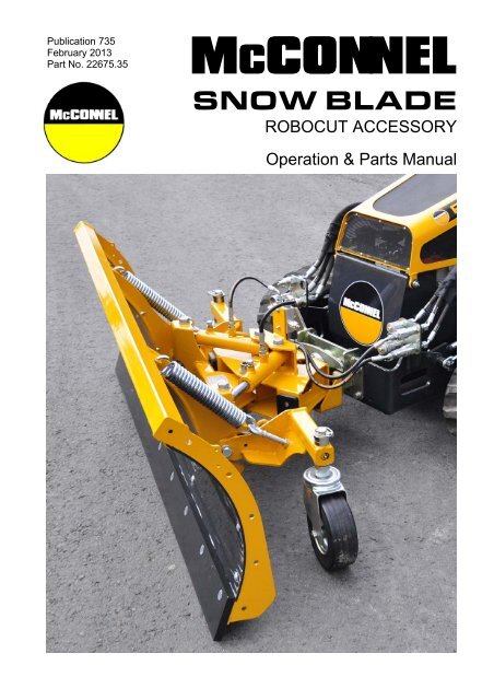
Publication 735February 2013Part No. 22675.35McCONNELSNOW BLADEROBOCUT ACCESSORYOperation & <strong>Parts</strong> <strong>Manual</strong>
IMPORTANTVERIFICATION OF WARRANTY REGISTRATIONDEALER WARRANTY INFORMATION & REGISTRATION VERIFICATIONIt is imperative that the selling dealer registers this machine with <strong>McConnel</strong> Limited beforedelivery to the end user – failure to do so may affect the validity of the machine warranty.To register machines go to the <strong>McConnel</strong> Limited web site at www.mcconnel.com, logonto ‘Dealer Inside’ and select the ‘Machine Registration button’ which can be found inthe Service Section of the site. Confirm to the customer that the machine has beenregistered in the section below.Should you experience any problems registering a machine in this manner please contactthe <strong>McConnel</strong> Service Department on 01584 875848.Registration VerificationDealer Name: ……………………..…………………………………………………………….Dealer Address: …….………………………………………………………………………….Customer Name: ……………………..…………………………………………………………Date of Warranty Registration: ……/……/...…… Dealer Signature: ………………..……NOTE TO CUSTOMER / OWNERPlease ensure that the above section above has been completed and signed by the sellingdealer to verify that your machine has been registered with <strong>McConnel</strong> Limited.IMPORTANT: During the initial ‘bedding in’ period of a new machine it is the customer’s responsibilityto regularly inspect all nuts, bolts and hose connections for tightness and re-tighten if required. Newhydraulic connections occasionally weep small amounts of oil as the seals and joints settle in – wherethis occurs it can be cured by re-tightening the connection – refer to torque settings chart below. Thetasks stated above should be performed on an hourly basis during the first day of work and at leastdaily thereafter as part of the machines general maintenance procedure.CAUTION: DO NOT OVER TORQUE HYDRAULIC FITTINGS AND HOSESTORQUE SETTINGS FOR HYDRAULIC FITTINGSHYDRAULIC HOSE ENDSPORT ADAPTORS WITH BONDED SEALSBSP Setting Metric BSP Setting Metric1/4” 18 Nm 19 mm 1/4” 34 Nm 19 mm3/8” 31 Nm 22 mm 3/8” 47 Nm 22 mm1/2” 49 Nm 27 mm 1/2” 102 Nm 27 mm5/8” 60 Nm 30 mm 5/8” 122 Nm 30 mm3/4” 80 Nm 32 mm 3/4” 149 Nm 32 mm1” 125 Nm 41 mm 1” 203 Nm 41 mm1.1/4” 190 Nm 50 mm 1.1/4” 305 Nm 50 mm1.1/2” 250 Nm 55 mm 1.1/2” 305 Nm 55 mm2” 420 Nm 70 mm 2” 400 Nm 70 mm
WARRANTY POLICYWARRANTY REGISTRATIONAll machines must be registered, by the selling dealer with <strong>McConnel</strong> Ltd, before delivery to the enduser. On receipt of the goods it is the buyer’s responsibility to check that the Verification of WarrantyRegistration in the <strong>Operator</strong>’s <strong>Manual</strong> has been completed by the selling dealer.1. LIMITED WARRANTIES1.01. All machines supplied by <strong>McConnel</strong> Limited are warranted to be free from defects in materialand workmanship from the date of sale to the original purchaser for a period of 12 months,unless a different period is specified.1.02. All spare parts supplied by <strong>McConnel</strong> Limited are warranted to be free from defects in materialand workmanship from the date of sale to the original purchaser for a period of 6 months.1.03. The manufacturer will replace or repair for the purchaser any part or parts found, uponexamination at its factory, to be defective under normal use and service due to defects inmaterial or workmanship. Returned parts must be complete and unexamined.1.04. This warranty does not apply to any part of the goods, which has been subjected to improper orabnormal use, negligence, alteration, modification, fitment of non-genuine parts, accidentdamage, or damage resulting from contact with overhead power lines, damage caused byforeign objects (e.g. stones, iron, material other than vegetation), failure due to lack ofmaintenance, use of incorrect oil or lubricants, contamination of the oil, or which has served itsnormal life. This warranty does not apply to any expendable items such as blades, flails, flapkits, skids, soil engaging parts, shields, guards, wear pads or pneumatic tyres.1.05. Temporary repairs and consequential loss - i.e. oil, downtime and associated parts arespecifically excluded from the warranty.1.06. Warranty on hoses is limited to 12 months and does not include hoses which have sufferedexternal damage. Only complete hoses may be returned under warranty, any which have beencut or repaired will be rejected.1.07. Machines must be repaired immediately a problem arises. Continued use of the machine after aproblem has occurred can result in further component failures, for which <strong>McConnel</strong> Ltd cannotbe held liable, and may have safety implications.1.08. Except as provided herein, no employee, agent, dealer or other person is authorised to give anywarranties of any nature on behalf of <strong>McConnel</strong> Ltd.1.09. For machine warranty periods in excess of 12 months the following additional exclusions shallapply:1) Hoses, external seals, exposed pipes and hydraulic tank breathers.2) Filters.3) Rubber mountings.4) External electric wiring.1.10. All service work, particularly filter changes, must be carried out in accordance with themanufacturer’s service schedule. Failure to comply will invalidate the warranty. In the event of aclaim, proof of the service work being carried out may be required.NB Warranty cover will be invalid if any non-genuine parts have been fitted or used. Use ofnon-genuine parts may seriously affect the machine’s performance and safety. <strong>McConnel</strong> Ltdcannot be held responsible for any failures or safety implications that arise due to the use ofnon-genuine parts.
2. REMEDIES AND PROCEDURES2.01. The warranty is not effective unless the Selling Dealer registers the machine, via the <strong>McConnel</strong>web site and confirms the registration to the purchaser by completing the confirmation form inthe operator’s manual.2.02. Any fault must be reported to an authorised <strong>McConnel</strong> dealer as soon as it occurs. Continueduse of a machine, after a fault has occurred, can result in further component failure for which<strong>McConnel</strong> Ltd cannot be held liable.2.03. Repairs should be undertaken within two days of the failure. Claims submitted for repairsundertaken more than 2 weeks after a failure has occurred, or 2 days after the parts weresupplied will be rejected, unless the delay has been authorised by <strong>McConnel</strong> Ltd.2.04. All claims must be submitted, by an authorised <strong>McConnel</strong> Service Dealer, within 30 days of thedate of repair.2.05. Following examination of the claim and parts the manufacture will pay, at their discretion, forany valid claim the cost of any parts and an appropriate labour allowance if applicable.2.06. The submission of a claim is not a guarantee of payment.2.07. Any decision reached by <strong>McConnel</strong> Ltd. is final.3. LIMITATION OF LIABILITY3.01. The manufacturer disclaims any express (except as set forth herein) and implied warrantieswith respect to the goods including, but not limited to, merchantability and fitness for a particularpurpose.3.02. The manufacturer makes no warranty as to the design, capability, capacity or suitability for useof the goods.3.03. Except as provided herein, the manufacturer shall have no liability or responsibility to thepurchaser or any other person or entity with respect to any liability, loss, or damage caused oralleged to be caused directly or indirectly by the goods including, but not limited to, any indirect,special, consequential, or incidental damages resulting from the use or operation of the goodsor any breach of this warranty. Notwithstanding the above limitations and warranties, themanufacturer’s liability hereunder for damages incurred by the purchaser or others shall notexceed the price of the goods.3.04. No action arising out of any claimed breach of this warranty or transactions under this warrantymay be brought more than one (1) year after the cause of the action has occurred.4. MISCELLANEOUS4.01. The manufacturer may waive compliance with any of the terms of this limited warranty, but nowaiver of any terms shall be deemed to be a waiver of any other term.4.02. If any provision of this limited warranty shall violate any applicable law and is held to beunenforceable, then the invalidity of such provision shall not invalidate any other provisionsherein.4.03. Applicable law may provide rights and benefits to the purchaser in addition to those providedherein.
DECLARATION OF CONFORMITYConforming to EU Machinery Directive 2006/42/ECWe,McCONNEL LIMITED, Temeside Works, Ludlow, Shropshire SY8 1JL, UKHereby declare that:The Product; <strong>Snow</strong> <strong>Blade</strong> Attachment for Remote Controlled MowerProduct Code; RMOWSerial No. & Date ………………………………… Type …………………………Manufactured in; ItalyComplies with the required provisions of the Machinery Directive 2006/42/ECThe machinery directive is supported by the following harmonized standards; BS EN ISO 14121-1 (2007) Safety of machinery - Risk assessment, Part 1:Principles Part 2: practical guide and examples of methods. BS EN ISO 12100-1 (2010) Safety of machinery - Part 1: Basic terminology andmethodology Part 2: Technical principles. BS EN 349(1993)+ A1 (2008) Safety of machinery - Minimum distances to avoid theentrapment with human body parts. BS EN 953 (1998) Safety of machinery - Guards General requirements for thedesign and construction of fixed and movable guards. BS EN 982(1996)+ A1 (2008) Safety requirements for fluid power systems and theircomponents. HydraulicsMcCONNEL LIMITED operates an ISO 9001:2008 quality management system,certificate number: FM25970.This system is continually assessed by the;British Standards Institution (BSI), Beech House, Milton Keynes, MK14 6ES, UKBSI is accredited by UK Accreditation Service, accreditation number: UKAS 003.The EC declaration only applies if the machine stated above is used inaccordance with the operating instructions.Signed …………………................ Responsible PersonCHRISTIAN DAVIES on behalf of McCONNEL LIMITEDStatus: General Manager Date: May 2011
For Safety and Performance…ALWAYS READ THIS BOOK FIRSTMcCONNEL LIMITEDTemeside WorksLudlowShropshireEnglandTelephone: 01584 873131www.mcconnel.comNOISE STATEMENTThe equivalent daily personal noise exposure from this machine measured at the operators’ ear is within the range 78 – 85dB, these figures apply to a normal distribution of use where the noise fluctuates between zero and maximum. The figuresassume that the machine is fitted to a tractor with a ‘quiet’ cab with the windows closed in a generally open environment.We recommend that the windows are kept closed. With the cab rear window open the equivalent daily personal noiseexposure will increase to a figure within the range 82 – 88 dB. At an equivalent daily noise exposure level of 85 – 90 dB earprotection is recommended and must always be used if any window is left open.
CONTENTS<strong>Operator</strong> SectionGeneral Information 1Introduction 2Machine Identification 3Identification of Components 3Specifications 4Safety Information 5Attachment & Operation 6Height Adjustment 7Maintenance 8<strong>Parts</strong> SectionChassis Module 12Hydraulic Installation 16
GENERAL INFORMATIONAlways read this manual before attempting to operate the machine – whenever any doubt existscontact your dealer or the <strong>McConnel</strong> Service Department for advice and assistance.Use only <strong>McConnel</strong> Genuine Service <strong>Parts</strong> on <strong>McConnel</strong> Equipment and MachinesDEFINITIONS – The following definitions apply throughout this manual:WARNINGAn operating procedure, technique etc., which –can result in personal injury or loss of life if not observed carefully.CAUTIONAn operating procedure, technique etc., which –can result in damage to either machine or equipment if not observed carefully.NOTEAn operating procedure, technique etc., which is –considered essential to emphasis.LEFT AND RIGHT HANDThese terms are applicable to the machine when it is viewed from the rear facing forwards.Note: The illustrations in this manual are for instructional purposes only and may on occasion not showsome components in their entirety. In some instances an illustration may appear slightly different to that ofyour particular model but the general procedure will be the same. E&OA.MACHINE & DEALER INFORMATIONRecord the Serial Number of your machine on this page and always quote this number whenordering parts. Whenever information concerning the machine is requested remember alsoto state the make and model of tractor to which the machine is fitted.Machine Serial Number:Machine Model details:Dealer Name:Dealer Address:Dealer Telephone No:Dealer Email Address:Installation Date:1
INTRODUCTIONThe <strong>McConnel</strong> ‘<strong>Snow</strong> <strong>Blade</strong>’ is a snow clearing attachment for use on <strong>McConnel</strong> RobocutMowers. It has been designed for use as a professional tool for the clearing snow on roads,pathways, parks, ramps and numerous other areas especially where accessibility is difficult orlimited.This machine must only be used to perform the duties for which it was designed; use of themachine for any other tasks will risk injury to persons and/or damage to the machine.2
MACHINE IDENTIFICATIONA machine identification plate is fitted to the machine in the location indicated below.Always quote the machine type and serial number as stated on the identification when orderingreplacement parts.IDENTIFICATION OF COMPONENTS1 Frame 6 Control Valve2 Scraper 7 Hydraulic Ram (Tilt)3 Rubber Covering 8 Mounting Plate4 Head Lift Springs 9 Caster Wheel5 Hydraulic Hoses (Tilt Function) 10 Spring Tension Screw3
SPECIFICATIONSMachine Weight: 123kg.4
SAFETY INFORMATIONIn addition to the general advice stated below, the main safety implicationssurrounding the use of this machine relate to the safe use of the Robocut machine; itis therefore vital that all users have read and understood all safety information in theoperation manual provided with that machine.Ensure that all users of this machine are trained in its safe use and have read theoperation manual for both this machine and the Robocut Mower.General Safety▲ Never run or attempt to operate the machine with safety devices missing or removed.▲ Never attempt to approach the machine whilst it is running or working.▲ Never attempt to use the machine to perform any duties it is not designed for.▲ Never allow persons to ride on the machine.▲ Never attempt to use a machine with damaged or missing components; repair or replace theparts immediately.▲ Read and abide by all safety message decals displayed on the machine; they are there foryour safety and the safety of others.▲ Keep all persons and animal at a safe distance from the working machine.▲ Stop the machine immediately if persons or animals enter into the working zone of themachine, do not restart operations until they are at a safe distance.▲ Before performing any work on the machine, including cleaning and maintenanceoperations, stop the Robocut, turn off the engine and remove the security key from the radiocontrol.▲ Be aware of all safety decals on the machine; know their meaning and abide by thewarnings stated.5
ATTACHMENT & OPERATIONAttachment and removal of the machine must always be performed on a firm level site. Ensurebystanders are kept at a safe distance from the machines during the attachment process. Theprocedure for attaching the machine to a Robocut is as follows;Align the Robocut until its mounting plate (a)is centred and parallel to the universal blade’smounting plate (b).Lower mounting plate (a) and move forwardsslowly until the two plates are in contact witheach other.Raise the mounting plate (a) until theuniversal blade’s mounting plate is fullyconnected.Turn off the Robocut and remove the securitykey from the controls.Fix mounting plate (a) to mounting plate (b)using the 6 screws in the location holes (c);secure in place with self-locking nuts.Connect the machines 2 ‘quick release’ hoses(d) to the Robocut’s external connectionpoints (e).Ensure that all connections are connectedcorrectly.Start the Robocut and carefully operate thecontrols to verify they correspond to theircorrect functions.Operating the Machine◄ Angling of the blade to the left or to the rightis controlled by the use of switch ‘f’ indicated.6
Height AdjustmentThe blade height is determined by the height position of the caster wheels (a), adjustment ofwhich is controlled by spacer washers (d); washers are placed on the wheel pin either above orbelow the support beam (c) to give the desired height. The wheel units are secured in placewith safety pins (b). Always make sure that the washers are placed in the same positions oneach of the two wheels to ensure the blade works parallel to the ground. See illustrations below.WARNING!This procedure must only be performed with the blade supported and secured so that it cannotfall during adjustment operations on the wheels. Failure to observe this can result in personalinjury and/or damage to the machine.7
MAINTENANCEWARNING: All maintenance, cleaning and repairing operations must be carried out whenthe engine is turned off and the starting key removed.Before performing any cleaning or maintenance operations, wait for the machine andequipment to cool down.The machine should be inspected on a daily basis prior to work to ensure it is in good workingcondition, the following points should be addressed during routine inspections;Check tightness of nuts and bolts, retighten if required.Check scraper for signs of wear and tear, replace if excessive damage is observed. Check hydraulic hoses and hydraulic connections for signs of damage or leakage,replace any damaged components immediately.Check wheels and wheel components, replaced any worn or damaged items if required.Lubricate machine at the required intervals.Scraper <strong>Blade</strong> ReplacementTo replace the scraper blade (a);- Loosen and remove clamping screws (b).- Remove blade and fit replacement.- Fix and secure in position by replacing theclamping screws (b).Wheel ReplacementTo replace a wheel (a);- Remove the safety pin (b).- Remove any spacer washers (d)above support (c).- Remove the wheel (a) from support (c).- Remove any spacers (d) from thewheel pin.- Replace the damaged or worn wheelwith a new one.- Repeat the operations described abovein reverse order. Ensure the safety pinhas been inserted properly (b).8
Replacing Hydraulic HosesCheck condition of hoses (a) and connectionsfor signs of damage or leakage on a regularbasis.Hydraulic hoses should be replacedperiodically (every 2000 hours or on a yearlybasis). Damaged hoses must be replacedimmediately.Lubrication PointsThe lubrication points indicated below should be greased every 50 hours.1 Ram Pivot Point 3 Articulation Joint2 Wheel Support 4 Mounting Unit9
SNOW BLADE<strong>Parts</strong> Section11
SNOW BLADE CHASSIS MODULEModule(s): 4000708McCONNEL12
SNOW BLADE CHASSIS MODULEModule(s): 4000708McCONNELREF. QTY. PART No. DESCRIPTION4000708 CHASSIS MODULE1 1 7315648 PIN2 2 4000671 SLIDING BLOCK3 2 4000672 HYDRAULIC RAM4 1 4000192 HEAD PIVOT BRACKET5 1 4000193 PIVOT JOINT6 1 4000673 BLADE7 1 4000669 RUBBER COVERING8 1 4000670 RUBBER BLADE9 1 4000674 ROCKER ARM10 1 4000675 BLADE CONNECTION11 2 4000676 CASTER WHEEL12 2 4000677 WHEEL PIN13 4 4000678 STOPPER BRACKET14 10 4000679 WASHER15 1 4000680 BLADE PROTECTION BRACKET16 4 4000038 HEX HEAD SCREW17 11 4000212 HEX HEAD SCREW18 2 4000681 HEX HEAD SCREW19 2 4000682 HEX HEAD SCREW20 4 4000683 HEX HEAD SCREW21 9 4000684 COUNTERSUNK HEAD SCREW22 4 4000685 COUNTERSUNK HEAD SCREW23 16 4000686 CUP HEAD BOLT24 2 4000580 CYLINDRIC HEAD SCREW25 4 4000472 FLANGED HEAD SCREW26 2 4000687 NUT27 2 4000110 SPRING28 2 4000416 AUTOGRIP NUT29 2 4000077 AUTOGRIP NUT30 2 9163003 NYLOC NUT31 20 9163004 NYLOC NUT32 4 4000221 LOCK NUT33 7 4000018 LOCK NUT34 2 4000688 LYNCH PIN35 2 4000689 ROD36 4 9100103 WASHER37 20 9100104 WASHER38 4 9100105 WASHER39 8 9100106 WASHER40 2 0100106 WASHER41 14 9100108 WASHER13Continued...
SNOW BLADE CHASSIS MODULEModule(s): 4000708McCONNEL14
SNOW BLADE CHASSIS MODULEModule(s): 4000708McCONNELREF. QTY. PART No. DESCRIPTION4000708 CHASSIS MODULE42 4 9100205 SPRING WASHER43 7 9100206 SPRING WASHER44 4 4000357 KNURLED WASHER45 2 4000116 BUFFER46 5 4000368 GREASER47 1 4000224 GREASER48 2 4000690 BUSH49 1 4000691 CONTROL VALVE50 1 4000237 BUSH51 1 4000238 WASHER15
SNOW BLADE HYDRAULIC INSTALLATIONModule(s): 4000709McCONNEL16
SNOW BLADE HYDRAULIC INSTALLATIONModule(s): 4000709McCONNELREF. QTY. PART No. DESCRIPTION4000709 HYDRAULIC INSTALLATION1 1 4000692 HYDRAULIC HOSE2 1 4000693 HYDRAULIC HOSE3 1 4000694 HYDRAULIC HOSE4 1 4000695 HYDRAULIC HOSE5 2 4000696 BLANKING PLUG6 1 4000132 QUICK RELEASE COUPLING7 1 4000140 * PLUG8 1 4000135 QUICK RELEASE COUPLING9 1 4000668 * PLUG10 2 4000579 CONNECTOR11 6 4000587 CONNECTOR12 2 4000697 RESTRICTOR* Optional Components17
<strong>McConnel</strong> Limited, Temeside Works, Ludlow, Shropshire SY8 1JL. England.Telephone: 01584 873131. Facsimile: 01584 876463. www.mcconnel.com


